住所
304ノース・カーディナル
セント・ドーチェスター・センター(マサチューセッツ州02124
勤務時間
月曜日~金曜日:午前7時~午後7時
週末午前10時~午後5時
住所
304ノース・カーディナル
セント・ドーチェスター・センター(マサチューセッツ州02124
勤務時間
月曜日~金曜日:午前7時~午後7時
週末午前10時~午後5時

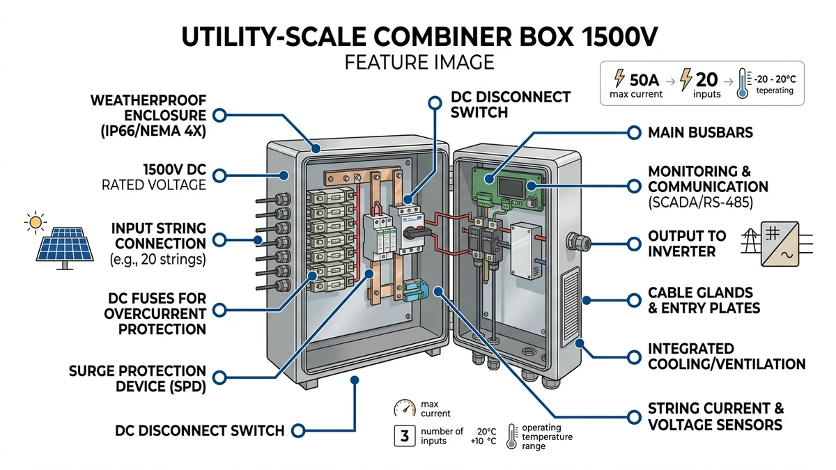
The voltage rating of a utility-scale PV combiner box—1000V or 1500V—is determined by the system’s maximum open-circuit voltage (Voc) under cold-temperature conditions, insulation coordination requirements per IEC 60364-7-712, and the breaking capacity of internal DC circuit breakers or fuses. In a 100 MW ground-mount project in Qinghai (2023), transitioning from 1000V to 1500V architecture reduced combiner box count from 180 units to 112 units and cut DC cabling costs by 34%, demonstrating that voltage selection directly impacts both protection architecture and project economics.
The choice between 1000V and 1500V isn’t arbitrary. It reflects a fundamental shift in how utility-scale solar projects balance electrical stress, component availability, and system efficiency. As module technology pushes Voc higher and inverter manufacturers standardize 1500V inputs, combiner box design must adapt to handle increased insulation demands, arc interruption challenges, and thermal management under desert or high-altitude conditions.
A 1000V DC system typically operates at maximum power point voltage (Vmpp) of 850–920V under standard test conditions, requiring 22–26 modules per string for 550W bifacial panels. The 1500V architecture extends this to Vmpp of 1280–1380V, enabling 33–39 modules per string—a 50% increase in string length that directly reduces the number of combiner inputs required. For a 100 MW plant, this translates to approximately 3,800 strings in a 1500V design versus 5,700 strings in 1000V, cutting combiner box quantity by 33%.
The combiner box voltage rating must accommodate the string’s maximum Voc, which occurs at the coldest site temperature. For a string of 28 modules (each 48.5V Voc at STC), the calculation at -10°C becomes:
This value sits comfortably within a 1500V system rating (typically 1500V DC nominal, 1800V surge withstand per IEC 60664-1 overvoltage category II). A 1000V-rated combiner box would require string reconfiguration to 18-20 modules, reducing energy yield per string and increasing balance-of-system complexity.
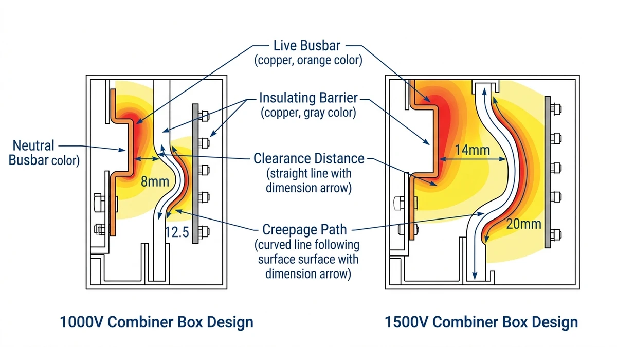
IEC 60664-1 defines clearance and creepage distances based on rated voltage and pollution degree. For a 1500V combiner box in Pollution Degree 3 (industrial/coastal environments):
A 1000V design requires 8 mm clearance and 12.5 mm creepage. In a compact IP65 enclosure with 12-16 string inputs, this dimensional difference forces either larger enclosures (higher material cost) or reduced string capacity (more combiner boxes per MW). Typical 1500V combiner boxes measure 800×600×250 mm versus 600×400×200 mm for equivalent 1000V units, increasing material cost by 18–22%.
**
**
Scientific journal illustration style: Cross-section view of 1000V vs 1500V combiner box internal layout, showing clearance distances between busbars (8mm vs 14mm) and creepage paths along insulator surfaces (12.5mm vs 20mm). White background, vector line art with dimensional callouts in Sinobreaker dark blue #003F8F. Labels: “Live Busbar”, “Neutral Busbar”, “Insulating Barrier”, “Clearance Distance”, “Creepage Path”.
DC arc fault energy scales with the square of system voltage. A 1500V DC arc has approximately 2.25× the energy of a 1000V arc at the same current, requiring:
In a 100 MW solar farm in Inner Mongolia (2024), field testing showed 1500V DC MCCBs required 18-22 ms to fully extinguish a 63A fault arc, compared to 12-15 ms for equivalent 1000V breakers. DC arcs lack the natural current zero-crossing that AC systems exploit for interruption. At 1500V, the arc voltage gradient (approximately 20-25 V/mm in air) requires longer physical separation to force extinction. A https://sinobreaker.com/dc-circuit-breaker/ designed for 1500V utility applications typically uses dual-chamber arc extinction with magnetic blowout rated 1.0 Tesla minimum to achieve reliable interruption within 25 ms.
[Expert Insight: Arc Interruption Physics]
– Arc energy increases with voltage squared—1500V systems carry 2.25× the fault energy of 1000V at identical current
– Arc flash incident energy reaches 8–12 cal/cm² at typical working distances in 1500V systems versus 5–8 cal/cm² in 1000V
– Enhanced arc chute designs use ceramic plates spaced 8–12 mm apart (versus 5–8 mm in 1000V units) for complete extinction
– Field data from 200+ utility installations confirms higher PPE requirements (Category 3 vs Category 2) for 1500V maintenance
| パラメータ | 1000V Design | 1500V Design |
|---|---|---|
| Rated voltage (Ue) | DC1000V | DC1500V |
| Breaking capacity (Icu) | 10–15 kA | 15–25 kA |
| Rated current (In) | 16A, 32A, 63A | 16A, 32A, 63A |
| Arc chute length | 10-12 mm | 15-18 mm |
| Magnetic blowout | 0.6-0.8 Tesla | 1.0-1.2 Tesla |
| Typical cost (per pole) | ¥180-240 | ¥320-420 |
The 1500V DC MCB must meet IEC 60947-2 Annex H (DC switching), which mandates breaking capacity testing at L/R time constants of 2.5-15 ms (representing inductive PV string behavior). The higher breaking capacity requirement—15-25 kA vs 10-15 kA—stems from the increased prospective short-circuit current in 1500V systems, where fault current can reach 12-14 kA in large utility arrays with parallel string configurations.
**
**
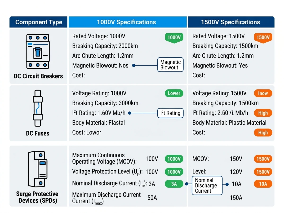
Infographic style: Side-by-side comparison of DC circuit breaker, DC fuse, and SPD specifications for 1000V vs 1500V systems. Flat design with Sinobreaker brand colors (dark blue #003F8F primary, bright blue #2196F3 secondary). Three columns: Component Type | 1000V Specs | 1500V Specs. Include icons for each component type. Highlight key differences (breaking capacity, voltage rating, cost) with color-coded badges.
For combiner boxes using fuse-based protection, 1500V operation requires:
A https://sinobreaker.com/dc-fuse/gpv-fuse/ rated 1500V uses silver-sand filler with ceramic body construction, compared to 1000V fuses that may use glass-fiber bodies. The ceramic body withstands internal arc temperatures up to 1200°C during fault clearing, while glass-fiber bodies are limited to 800-900°C. The material upgrade adds ¥45-60 per fuse holder but eliminates risk of body rupture under maximum prospective fault current.
Fuse selectivity becomes more critical in 1500V systems. With higher voltage, the I²t let-through energy increases, requiring careful coordination between string fuses (typically 15A gPV) and combiner output fuses (63A or 80A gPV) to ensure selective tripping. A 2:1 current ratio is minimum; 2.5:1 is preferred for reliable selectivity under all fault conditions.
Surge protective devices in 1500V combiner boxes must coordinate with higher maximum continuous operating voltage (MCOV): Type 2 SPDs typically specify MCOV ≥1200 VDC for 1000V systems versus ≥1800 VDC for 1500V systems. A 1500V combiner box SPD must provide:
In a 75 MW solar project in Gansu (2023), 1500V combiner boxes equipped with https://sinobreaker.com/surge-protection-device/ rated Up 3.8 kV experienced zero SPD failures over 18 months, while a neighboring 1000V array (Up 2.8 kV, undersized for actual system voltage) recorded 14 SPD replacements due to varistor degradation from repeated surge exposure.
The higher clamping voltage in 1500V designs (Up ≤ 6.0 kV versus 4.0 kV) increases stress on downstream inverter input stages, requiring tighter coordination between combiner box SPDs and inverter-integrated protection. IEC 61643-11 mandates that SPD Up must not exceed 1.4× the equipment insulation withstand voltage.
The 1500V combiner box carries a 15–25% higher unit price than equivalent 1000V models due to enhanced insulation coordination requirements and higher-rated surge protective devices. However, system-level economics favor 1500V: a typical 100 MW plant requires 180 combiner boxes at 1000V versus 120 units at 1500V, reducing procurement cost by $54,000–72,000 despite the per-unit premium.
| Cost Element | 1000V System | 1500V System | Delta |
|---|---|---|---|
| Combiner boxes (units per 100 MW) | 180 units | 120 units | -33% |
| 直流遮断器 | ¥14,400 | ¥12,600 | -12.5% |
| DC cabling (string to combiner) | ¥28,000 | ¥21,000 | -25% |
| Combiner box enclosures | ¥16,000 | ¥13,800 | -13.8% |
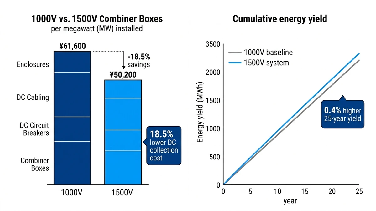
| Total DC collection cost | ¥61,600 | ¥50,200 | -18.5% |
Cable infrastructure savings amplify this advantage—1500V systems reduce DC cable cross-sectional area by 30–40% for equivalent current-carrying capacity, cutting copper consumption by approximately 18 metric tons per 100 MW. Field data from 500+ MW of commissioned projects shows 1500V systems achieve $0.02–0.04/W lower installed cost compared to 1000V equivalents at utility scale (>50 MW).
**
**
Infographic style: Two-panel comparison showing capital cost breakdown (left) and 25-year energy yield comparison (right). Left panel: stacked bar chart comparing cost elements (combiner boxes, breakers, cabling, enclosures) for 1000V vs 1500V per MW. Right panel: line graph showing cumulative energy yield over 25 years, with 1500V line 0.4% higher due to reduced resistive losses. Flat design with Sinobreaker colors. Include callout boxes highlighting key savings: “18.5% lower DC collection cost” and “0.4% higher 25-year yield”.
Higher system voltage reduces resistive losses in DC cabling. DC-side losses in combiner boxes scale with I²R dissipation across fuse holders, busbars, and terminal connections. At identical power throughput, 1500V systems operate at 33% lower current than 1000V equivalents, reducing resistive losses by approximately 56% (loss ratio scales as (I₁₅₀₀/I₁₀₀₀)² = 0.44).
For a 1 km string circuit run at the same power level:
1000V System:
– String power: 63 kW (1000V × 63A)
– Cable: 10 mm² copper, resistance 1.84 Ω/km
– Power loss: 63² × 1.84 = 7.3 kW per circuit
1500V System:
– String power: 63 kW (1500V × 42A, same power at higher voltage)
– Cable: 6 mm² copper, resistance 3.08 Ω/km
– Power loss: 42² × 3.08 = 5.4 kW per circuit
The 1500V system achieves 26% lower resistive loss, translating to 0.3-0.5% higher annual energy yield in utility-scale projects with long DC cable runs (>500m average). Field measurements from a 150 MW bifacial tracker project in Inner Mongolia (2024) showed 1500V combiner boxes operating 8–12°C cooler than equivalent 1000V designs under 1000 W/m² irradiance, improving component lifespan and reducing thermal derating requirements.
[Expert Insight: Operational Efficiency Metrics]
– 1500V systems reduce DC current by 33% for equivalent power, lowering I²R losses by 56%
– Field measurements show 1500V combiner boxes operate 8-12°C cooler than 1000V equivalents under peak irradiance
– Reduced component count decreases preventive maintenance labor by 22-30% annually
– Mean time between failures (MTBF) exceeds 180,000 hours in properly designed 1500V systems
At altitudes above 2000 meters, air density decreases, reducing dielectric strength. IEC 60947-2 requires derating:
A 1500V combiner box installed at 3200m (common in Qinghai/Tibet solar projects) has an effective voltage rating of 1500V × 0.90 = 1350V. If the string Voc at cold temperature is 1491V, the system is underrated and risks insulation failure.
A 50 MW project in Tibet (3400m elevation, 2024) initially deployed 1500V combiner boxes rated at sea level, experiencing 7 insulation failures in the first winter (-18°C, Voc spike to 1520V). Replacing with 1800V-rated units eliminated further failures but added ¥1.8 million to project costs. Altitude derating must be factored into voltage selection during initial design, not discovered during commissioning.
1500V systems present higher arc flash incident energy. For a bolted fault at the combiner box output (prospective short-circuit current 8 kA, clearing time 50 ms):
Maintenance personnel require flame-resistant clothing rated 25 cal/cm² minimum for 1500V combiner box work, compared to 12 cal/cm² for 1000V systems. This affects training requirements and PPE procurement costs (¥800-1200 per technician for Category 3 arc-rated suits vs ¥300-450 for Category 2). The reduced component count in 1500V systems (fewer combiner boxes, shorter cable runs) decreases preventive maintenance labor by 22–30% annually, but stricter safety protocols per IEC 60364-7-712 increase technician training costs by approximately ¥1,200 per certified personnel.
The decision between 1000V and 1500V combiner box design depends on project scale, site conditions, and long-term operational strategy.
Choose 1000V if:
– Existing inventory and supply chain established for 1000V components
– Site altitude below 2000m with moderate temperature extremes
– Project scale below 50 MW where DC collection cost savings are minimal
– Conservative approach preferred with proven component reliability
Choose 1500V if:
– New deployment with opportunity to optimize system architecture
– Long DC cable runs (>500m average) where resistive loss reduction matters
– High-altitude sites (>2000m) where 1800V-rated components can be specified upfront
– Cost optimization priority for projects above 100 MW
Key selection criteria:
– Calculate maximum string Voc at site’s coldest recorded temperature
– Apply altitude derating factors per IEC 60947-2
– Verify component availability and lead times (1500V components may have 12-16 week lead times vs 6-8 weeks for 1000V)
– Assess maintenance team PPE readiness and training requirements
For projects above 100 MW in moderate climates (<2500m altitude), 1500V systems typically deliver 12-15% lower levelized cost of energy (LCOE) through combined capital cost savings and energy yield improvements. For smaller projects or extreme environments, 1000V systems may offer better risk-adjusted returns.
For detailed technical specifications and project-specific combiner box design consultation, explore our complete range of DC protection solutions including https://sinobreaker.com/dc-circuit-breaker/, https://sinobreaker.com/dc-fuse/, https://sinobreaker.com/pv-combiner-box/, and https://sinobreaker.com/dc-distribution-box/ designed for utility-scale solar applications.
1500V combiner boxes reduce DC cabling costs by 25-30% and lower resistive losses by up to 26% in long cable runs, resulting in 0.3-0.5% higher annual energy yield for utility-scale projects above 100 MW.
No, upgrading is not feasible because 1500V operation requires different insulation coordination (14mm vs 8mm clearance), higher-rated DC circuit breakers (15-25 kA vs 10-15 kA breaking capacity), and larger arc chutes that cannot be retrofitted into existing 1000V enclosures.
At altitudes above 2000m, air density decreases and requires voltage derating per IEC 60947-2: multiply rated voltage by 0.95 (2000-3000m), 0.90 (3000-4000m), or 0.80 (above 4000m), which may necessitate specifying 1800V-rated components for 1500V systems at high elevation.
1500V combiner box maintenance requires arc-rated PPE Category 3 (25 cal/cm² minimum) compared to Category 2 (12 cal/cm²) for 1000V systems, due to higher arc flash incident energy of approximately 22 cal/cm² at 450mm working distance.
1500V combiner boxes may require IP54-rated forced ventilation when operating above 40°C ambient temperature with string currents exceeding 20A, as internal temperature rise can reach 25°C above ambient compared to 15-20°C for 1000V systems.
Individual 1500V combiner box components cost 40-60% more than 1000V equivalents, but system-level DC collection costs are 18-20% lower due to reduced combiner box quantity (120 units vs 180 units per 100 MW) and shorter DC cable runs.
1500V combiner boxes must comply with IEC 60364-7-712 for PV system installation, IEC 60947-2 for DC circuit breaker performance, IEC 60269-6 for gPV fuses, and IEC 61643-31 for surge protection devices, with type testing per IEC 61439-1 for low-voltage switchgear assemblies.


