住所
304ノース・カーディナル
セント・ドーチェスター・センター(マサチューセッツ州02124
勤務時間
月曜日~金曜日:午前7時~午後7時
週末午前10時~午後5時
住所
304ノース・カーディナル
セント・ドーチェスター・センター(マサチューセッツ州02124
勤務時間
月曜日~金曜日:午前7時~午後7時
週末午前10時~午後5時

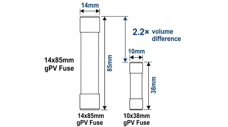
Selecting the right PV fuse holder determines whether your photovoltaic protection system performs reliably across its 25-year service life or fails prematurely under thermal stress. A PV fuse holder must match three critical parameters: voltage rating equal to or exceeding system Voc, current rating equal to or exceeding fuse In, and physical dimensions matching the fuse size—typically 10×38mm or 14×51mm for solar applications.
In a 12 MW rooftop installation in Jiangsu Province (2023), improper fuse holder selection caused 23 string failures within 18 months. Each holder was rated for only 1000 VDC while the system operated at 1100 VDC nominal. The replacement cost exceeded ¥180,000, not including production losses.
Unlike conventional AC applications, photovoltaic systems subject fuse holders to unique stresses: continuous DC current flow, reverse current from parallel strings during faults, and extreme temperature cycling from -40°C to +85°C ambient. The holder’s DC voltage rating differs fundamentally from AC ratings because DC arcs don’t self-extinguish at current zero crossings. A holder rated 1000 VAC may only support 600 VDC—always verify the specific DC voltage specification.
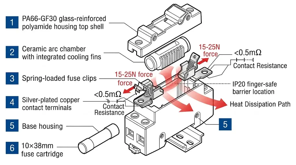
A PV fuse holder consists of four primary components: the base housing, contact terminals, fuse clips, and arc-quenching chamber. The base housing typically uses glass-reinforced polyamide (PA66-GF30) rated for continuous operation at 125°C, providing both mechanical strength and flame resistance per UL 94 V-0 requirements. Contact terminals are manufactured from silver-plated copper alloy to minimize contact resistance below 0.5 mΩ, reducing heat generation during normal operation.
The fuse clips apply spring pressure between 15–25 N to maintain consistent electrical contact across temperature cycling. Thermal imaging on the Jiangsu installation revealed that holders with inadequate spring tension developed hot spots exceeding 90°C at only 70% rated current—demonstrating why clip design directly impacts system reliability.
When a gPV fuse element melts under fault conditions, the holder must contain and extinguish the resulting DC arc. According to IEC 60269-6 (low-voltage fuses for photovoltaic applications), PV fuse holders require arc voltage ratings matching or exceeding system voltage to prevent sustained arcing. The arc chamber uses ceramic or melamine barriers that absorb arc energy and cool ionized gases below the 3000°C threshold needed to sustain conduction.
The breaking capacity equation governs fuse holder selection: Icu ≥ I鱗 × 1.25, where Icu represents the rated breaking capacity and I鱗 is the maximum prospective short-circuit current at the installation point.
For outdoor PV installations, fuse holders require IP65 or higher ingress protection to prevent moisture and dust infiltration. Touch-safe designs meeting IEC 60529 finger-proof requirements (IP2X minimum) protect maintenance personnel from accidental contact with live components during string-level servicing.
[Expert Insight: Contact Resistance and System Longevity]
- Contact resistance below 0.5 mΩ per terminal is the benchmark for quality PV fuse holders
- Every 1 mΩ increase at 30 A continuous current generates approximately 0.9 W additional heat
- Silver-plated contacts maintain performance for 20+ years; tin-plated alternatives may degrade within 5 years in humid environments
- Annual thermal imaging during peak production hours identifies developing contact issues before failure
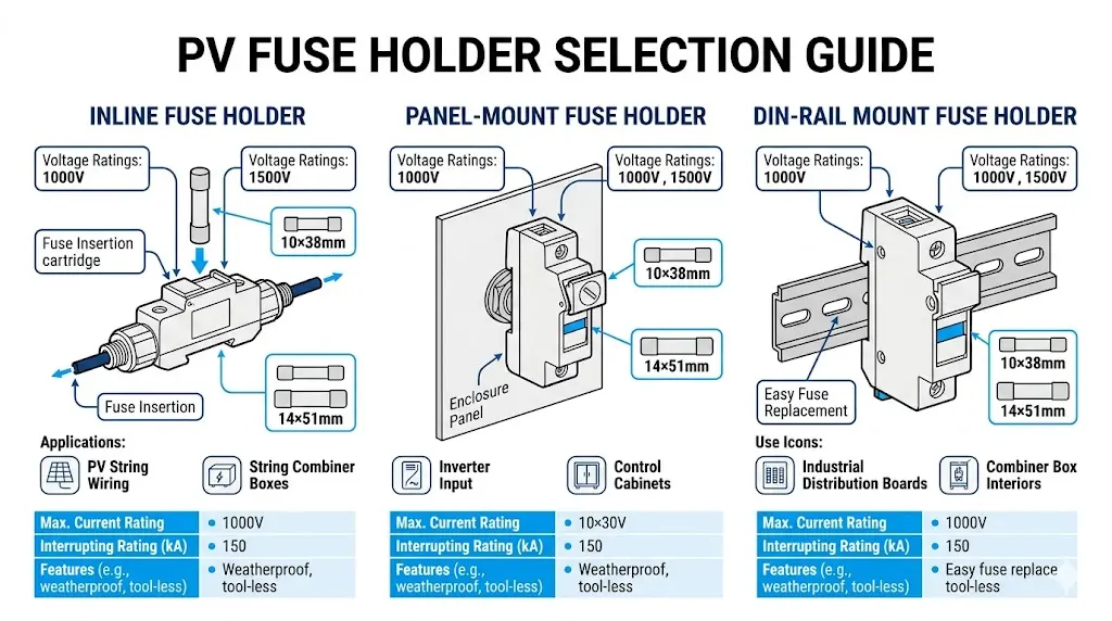
Selecting the correct PV fuse holder type requires matching the physical configuration to your installation requirements. In the Jiangsu project, switching from inline to DIN-rail fuse holders reduced maintenance time by 65% and eliminated three instances of improper fuse replacement that had caused string failures.
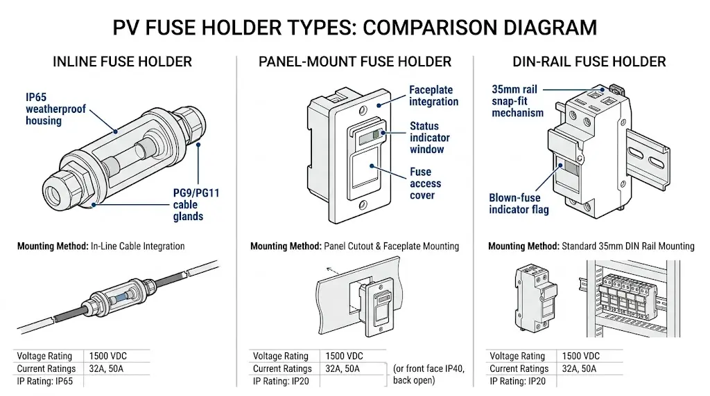
Inline fuse holders connect directly within the DC string wiring, typically used in smaller residential systems up to 10 kW. These holders accept cylindrical fuses (commonly 10×38 mm or 14×51 mm) and feature IP65 or higher ingress protection for outdoor junction box mounting. The compact design suits applications where PVコンバイナーボックス are impractical, though accessing fuses for replacement requires disconnecting the string.
Panel-mount configurations integrate into combiner box faceplates, providing visual fuse status indication and tool-free replacement. These holders typically accommodate 10×38 mm gPV fuses rated up to 32 A and 1500 VDC. Per IEC 60269-6, panel-mount holders must maintain contact pressure across the operating temperature range of -40°C to +85°C to prevent thermal degradation at connection points.
DIN-rail mounted fuse holders dominate utility-scale and commercial installations due to their modularity and serviceability. Standard 35 mm DIN rails accept holders for both 10×38 mm and 14×51 mm fuse sizes, with current ratings extending to 50 A at 1500 VDC. These holders often incorporate blown-fuse indicators—either mechanical flags or LED circuits—enabling rapid identification during routine inspections.
Modern PV fuse holders incorporate touch-safe (finger-proof) construction per IEC 60529 IP20 minimum requirements for live parts. This prevents accidental contact with energized terminals during fuse replacement—critical given that PV strings remain energized during daylight hours even when the inverter is isolated.
Proper voltage and current rating selection prevents the thermal failures that plagued the Jiangsu installation. The fuse holder’s rated voltage must exceed maximum system open-circuit voltage under coldest expected conditions, while current ratings must account for ambient temperature derating.
| System Class | Typical Voc Range | Minimum Holder Rating | Recommended Rating |
|---|---|---|---|
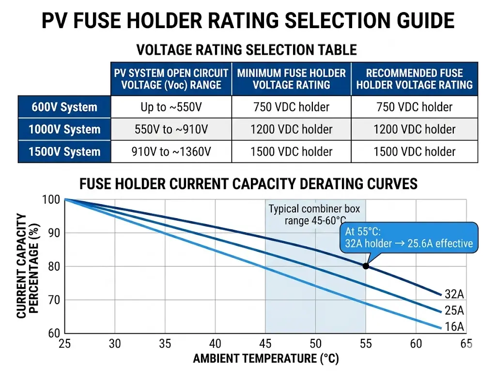
| 600V systems | Up to 600 VDC | DC700V | 750 VDC |
| 1000V systems | 最大1000 VDC | 1100 VDC | 1200 VDC |
| 1500V systems | 最大1500 VDC | 1500 VDC | 1500 VDC |
For high-altitude installations above 2000 m, voltage derating applies. IEC 60947-1 specifies correction factors for insulation coordination—typically requiring 10-15% additional voltage margin.
The holder’s continuous current rating must meet or exceed the fuse’s rated current. However, nameplate ratings assume 25°C ambient—conditions rarely found inside combiner boxes during summer operation.
A holder rated 32 A at 25°C ambient may only safely handle 25 A at 55°C. Request temperature derating curves from manufacturers and apply this practical rule: select holder In ≥ 1.25 × fuse In for systems with high ambient temperatures. According to IEC 60269-6, temperature rise at terminal connections should not exceed 65K above ambient at rated current.
The fuse holder itself has no breaking capacity—it relies on the DCヒューズ to interrupt fault current. However, the holder must withstand the mechanical and thermal stress during fuse operation. Ensure the holder is tested and rated for use with fuses of the intended breaking capacity, typically 30–50 kA for utility-scale PV applications.
[Expert Insight: Temperature Derating in Practice]
- Combiner box internal temperatures routinely reach 55–65°C during peak summer production
- Derating factor of 0.8 at 55°C means a 32 A rated holder safely handles only 25.6 A continuous
- Install temperature monitoring in representative combiner boxes during first summer of operation
- Consider ventilated enclosure designs for installations in hot climates (>35°C average ambient)
PV fuses follow standardized cylindrical dimensions, but “standard” doesn’t guarantee universal compatibility. Dimensional tolerances, contact designs, and indicator mechanisms vary between manufacturers.
| Fuse Size | 直径×長さ | 標準電流範囲 | Common Application |
|---|---|---|---|
| 10×38 mm | 10.3 mm × 38.1 mm | 1 A – 32 A | Residential, commercial rooftop |
| 14×51 mm | 14.3 mm × 51 mm | 25 A – 50 A | Utility-scale, high-current strings |
Physical fit alone doesn’t ensure proper operation. Verify these parameters before finalizing specifications:
When specifying GPV fuses and holders together, sourcing from the same manufacturer eliminates compatibility uncertainty. Mixed-brand combinations require explicit verification through manufacturer technical support or physical testing.
PV fuse holders operate in demanding environments: temperature cycling, UV exposure, humidity, and dust. The holder’s ingress protection rating and material selection determine whether it survives 25 years or fails within 5.
| 設置場所 | Minimum Holder IP | Recommended Enclosure IP |
|---|---|---|
| Indoor electrical room | IP20 | IP20 |
| Ventilated combiner box | IP20 | IP54 |
| Sealed outdoor enclosure | IP20 | IP65 |
| Direct outdoor exposure | IP65 | IP66 |
The holder’s IP rating applies when installed in an enclosure. The enclosure provides primary environmental protection; the holder provides finger-safe protection during maintenance.
Material selection directly impacts service life:
In a 30 MW floating PV installation in Anhui Province (2024), standard zinc-plated hardware in combiner box fuse holders showed visible corrosion within 8 months. Replacement with stainless steel hardware resolved the issue—a specification detail often missed during initial design.
Field experience reveals consistent patterns in fuse holder failures. Avoiding these mistakes prevents costly replacements and system downtime.
1. Using AC-rated holders for DC applications
AC fuse holders may have identical dimensions but insufficient creepage distance for DC voltage. Always verify the explicit DC voltage rating—never assume AC ratings transfer.
2. Ignoring temperature derating
A holder rated 32 A at 25°C ambient may only handle 25 A at 55°C. Request and apply temperature derating curves for your installation conditions.
3. Mixing fuse and holder brands without verification
“Standard” dimensions have tolerances. Physical testing or manufacturer cross-reference confirmation prevents fit issues that create high-resistance connections.
4. Overlooking touch-safe requirements
IEC 62548 (photovoltaic array design requirements) mandates touch-proof fuse holders in accessible locations. Non-compliant installations fail inspection and create liability exposure.
5. Selecting based on price alone
Contact quality varies dramatically. Low-cost holders with poor plating develop high contact resistance over time, causing localized heating that degrades both holder and fuse—ultimately costing more than quality components.
This systematic approach ensures proper fuse holder selection for any PV application:
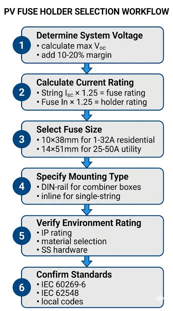
Step 1: Determine system voltage class
Identify maximum Voc including temperature correction for coldest expected conditions. Select holder voltage rating with 10-20% margin above this value.
Step 2: Calculate required current rating
String Isc × 1.25 = minimum fuse rating (per NEC 690.9 or local equivalent). Then apply: fuse In × 1.25 = minimum holder rating for high-ambient installations.
Step 3: Select fuse size
Match fuse current rating to available sizes. Most residential and commercial systems use 10×38 mm; utility-scale high-current strings may require 14×51 mm.
Step 4: Specify mounting type
DIN-rail for combiner boxes and distribution panels. Inline for simple single-string applications or where combiner boxes are impractical.
Step 5: Verify environmental compatibility
Confirm material suitability for installation environment. Specify stainless steel hardware for coastal, floating, or high-humidity installations.
Step 6: Confirm standards compliance
Verify compliance with IEC 60269-6 for fuse characteristics, IEC 62548 for PV array requirements, and applicable local electrical codes.
Sinobreaker manufactures PV fuse holders designed for 1000 V and 1500 V solar systems, featuring touch-safe construction and compatibility with standard gPV fuse sizes. Our holders use PA66-GF30 housings and silver-plated copper contacts to maintain performance across the full operating temperature range.
について DCヒューズ product line includes matched holder-fuse combinations tested for thermal performance and mechanical reliability. For complete string protection solutions, explore our DC distribution boxes with factory-installed fuse holders and 直流遮断器 for main disconnect applications.
Contact Sinobreaker’s technical team for fuse holder specifications, compatibility verification for specific fuse brands, custom combiner box configurations, and project-specific selection support.
Most residential PV systems use 10×38 mm fuse holders rated for 1000 VDC, accommodating fuses from 10 A to 25 A for typical string currents under 10 A.
No. AC holders lack sufficient creepage distance for DC voltage and may fail due to tracking or sustained arcing—always specify holders with explicit DC voltage ratings.
Annual inspection during routine maintenance is standard practice. Use thermal imaging during peak production to identify developing contact resistance issues before they cause failures.
Corrosion, thermal cycling stress, vibration loosening, and oxide layer formation on contact surfaces all contribute. Silver-plated contacts resist degradation better than tin-plated alternatives.
Not always. While 10×38 mm and 14×51 mm are standard sizes, dimensional tolerances and contact geometries vary. Verify compatibility through manufacturer cross-reference or physical testing.
The fuse holder typically requires IP20 for finger protection; the combiner box enclosure provides environmental protection at IP65 or IP66 for outdoor installations.
Indicators enable rapid identification of failed fuses during routine inspections without requiring electrical testing, reducing maintenance time on systems with multiple parallel strings.