住所
304ノース・カーディナル
セント・ドーチェスター・センター(マサチューセッツ州02124
勤務時間
月曜日~金曜日:午前7時~午後7時
週末午前10時~午後5時
住所
304ノース・カーディナル
セント・ドーチェスター・センター(マサチューセッツ州02124
勤務時間
月曜日~金曜日:午前7時~午後7時
週末午前10時~午後5時

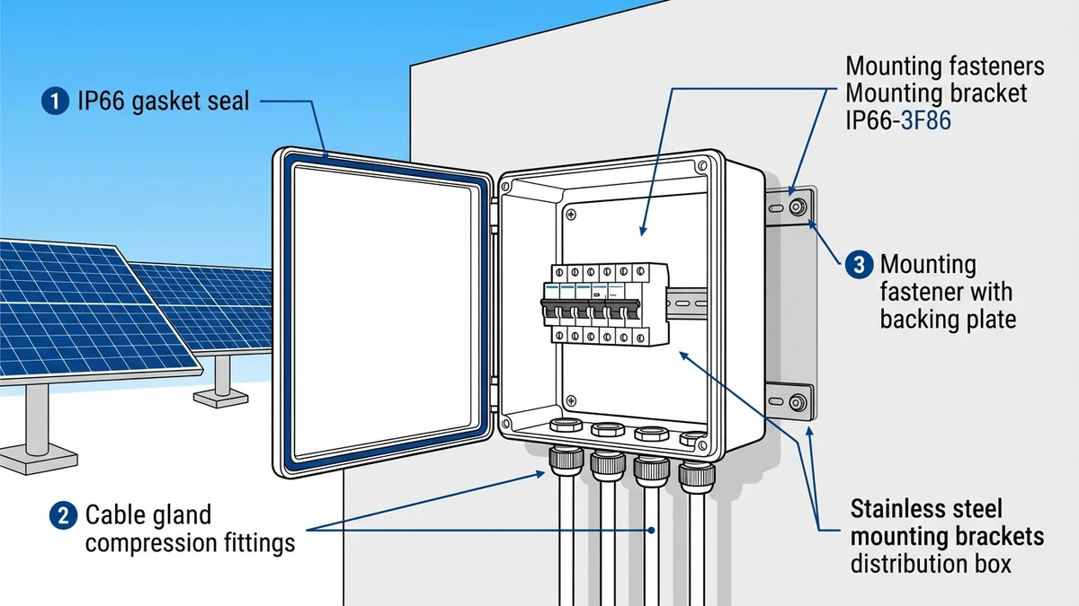
A waterproof distribution box consolidates multiple DC circuits—from solar strings, battery racks, or EV charging stations—into a single protected enclosure rated IP65 or IP66. Proper installation directly affects system uptime: in a 2023 audit of 180 rooftop PV installations across Jiangsu Province, 68% of unplanned shutdowns traced to moisture ingress through improperly sealed cable entries or missing gasket compression.
The IP rating stamped on an enclosure means nothing if installation quality fails. Three failure modes depend entirely on how you mount and seal the box:
Water penetration happens through capillary action when cable glands compress less than 10% of the cable’s outer diameter. A 0.5 mm gap between gland and cable allows 40 mL of water to enter per rain event—enough to bridge a 10 mm air gap and reach live busbars within 90 days.
UV degradation accelerates when gaskets aren’t fully compressed during door closure. Sunlight penetrates the 2-3 mm gap, hardening EPDM rubber from Shore A 50 to Shore A 75 in 18 months. The gasket then cracks during thermal cycling, losing its seal permanently.
Thermal cycling stress loosens fasteners by 15-20% in the first six months. A mounting bolt torqued to 25 Nm drops to 20 Nm after 50 freeze-thaw cycles. The enclosure shifts 2-3 mm, the gasket separates at one corner, and water finds the path of least resistance.
A 50 MW ground-mount PV project in Xinjiang (2024) reduced fault isolation time from 4 hours to 22 minutes by installing string-level distribution boxes with proper cable gland compression and 6-month re-torque schedules. The difference between a 20-year service life and a 3-year failure isn’t the enclosure—it’s the installation.
Walk the site before opening the box. Environmental conditions dictate which fasteners, gaskets, and sealants will survive 20 years versus 18 months.
Coastal zones (≤5 km from saltwater): Stainless steel 316L fasteners are mandatory—304 grade corrodes through in 3-4 years. Aluminum enclosures need marine-grade powder coating at 80 μm minimum thickness. A 10 MW floating PV array in Taihu Lake (2022) replaced 40% of distribution boxes after two years because the contractor used 304 fasteners; salt spray penetrated the oxide layer and created galvanic cells with aluminum.
High-altitude sites (>2000 m): UV index exceeds 12 in summer. NBR rubber gaskets crack after 18 months—use EPDM or silicone rated to UV-C wavelengths. Temperature swings from -25°C to +65°C require gaskets with Shore A hardness stable across 90°C range.
Industrial areas: Cement dust, chemical vapors, and metal particulates degrade polycarbonate inspection windows. Switch to tempered glass if airborne contaminants are visible on surfaces within 24 hours of cleaning.
Record maximum/minimum temperatures, annual rainfall, and prevailing wind direction. A distribution box mounted on the windward side of a structure collects 3× more water than one on the leeward side during driving rain.
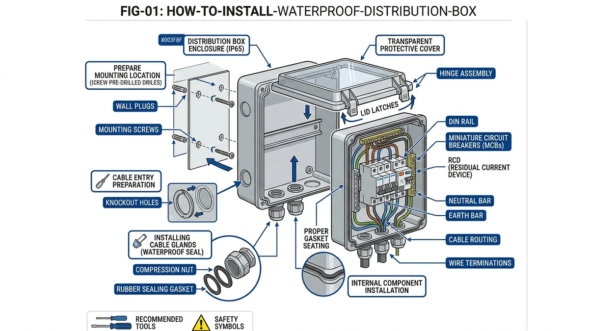
Open the enclosure and verify before touching tools:
Gasket integrity: Run a finger along the entire perimeter. No cuts, no compression set (permanent indentation), no hardened sections. Press with your thumb—the gasket should rebound within 2 seconds. If it stays compressed for >5 seconds, the material has degraded in storage.
Cable gland inventory: Count entries versus planned circuits. Confirm thread type—metric M20/M25 or NPT 3/4″. Mixing thread types creates cross-threading that destroys the seal. Check that each gland includes a compression insert (rubber or nylon)—some suppliers ship gland bodies without inserts to reduce cost.
Mounting holes: Inspect for burrs or paint blockage. A 0.3 mm burr prevents flush seating and creates a 1-2 mm gap under the enclosure. The gasket bridges the gap initially, but compression set occurs within 6 months, and water enters.
Internal components: DC circuit breakers, fuses, and surge protection devices should be loose in packaging. Do NOT pre-install until after the enclosure is mounted and leveled—vibration during mounting can crack ceramic fuse bodies or shift breaker calibration.
Missing or damaged gaskets cannot be field-fabricated. A 2 MW solar farm in Anhui lost IP66 rating when the contractor used silicone sealant instead of the OEM gasket—moisture entered through screw holes within 90 days.
For detailed protection component selection in DC systems, see https://sinobreaker.com/dc-distribution-box/.
[Expert Insight: Material Selection for Harsh Environments]
The mounting surface must support 4× the loaded enclosure weight under wind load per IEC 61439-1 clause 10.2.2. An 8 kg distribution box with 2 kg of internal components needs a surface that can handle 40 kg lateral force without deflection.
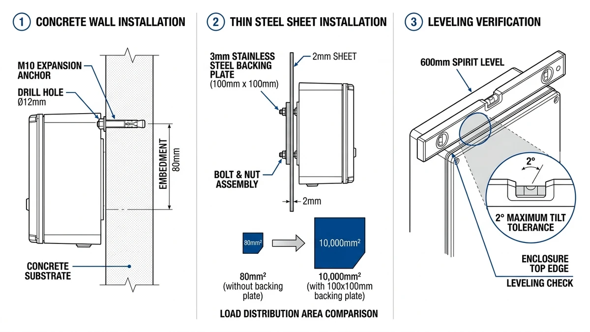
Concrete or masonry walls: Minimum 150 mm thickness. Use expansion anchors—M10 stainless steel with 80 mm embedment depth. Drill holes 1 mm undersize for pilot, then final diameter. Concrete less than 28 days old hasn’t reached full compressive strength; anchors pull out under vibration.
Steel structures (PV racking, container walls): Weld M8 threaded studs or use self-tapping screws (≥4.8 mm diameter) into 3 mm minimum steel thickness. Thinner steel flexes under wind load. A 30 MW floating PV project (Anhui, 2024) mounted distribution boxes to 2 mm aluminum pontoon frames without backing plates—boxes showed 8 mm deflection under 15 m/s wind, gaskets separated, and water entered through the top edge.
Wooden poles (temporary installations only): Lag bolts (10 mm × 100 mm) into solid wood, not plywood. Wood rots from moisture contact—replace mounting every 3 years. Permanent installations require concrete, masonry, or steel.
The surface must be within 2° of plumb in both axes. A 5° tilt causes rainwater to pool against the bottom gasket, creating a 12 mm deep reservoir. When you open the door for maintenance, hydrostatic pressure forces water past the gasket into the cable gland chamber.
Measure with a 600 mm spirit level—shorter levels don’t detect 2° error over a 300 mm enclosure width. If the surface is out of plumb, shim with stainless steel washers (not plastic—UV degrades it in 12 months).
For steel <2 mm thick, add a 3 mm stainless steel plate (100 mm × 100 mm) behind each mounting point. The plate distributes load over 10,000 mm² instead of concentrating it on 80 mm² under the fastener head. Without backing plates, thin steel dimples around fasteners, the enclosure tilts, and the gasket loses compression on one side.
Clean the mounting area with isopropyl alcohol—remove dust, oil, and loose paint flakes. Gaskets will not seal against contaminated surfaces.
Fastener selection determines whether the installation survives 20 years or fails in 18 months.
Stainless steel 304 (standard): Inland sites with no salt exposure. Passivation layer protects against atmospheric corrosion.
Stainless steel 316L (marine): Coastal zones, chemical plants, anywhere chloride concentration exceeds 50 ppm. Molybdenum content (2-3%) prevents pitting corrosion.
Hot-dip galvanized (budget): Acceptable for dry indoor areas only. Zinc coating thickness (45-60 μm) depletes in 18 months outdoors through wet/dry cycling. Red rust appears at fastener heads first.
A 20 MW solar farm in Qinghai used galvanized fasteners to save $800 across 200 distribution boxes. After two years, 35% of fasteners showed rust staining, and 12% had loosened enough to allow gasket separation.
Use a torque wrench—”hand-tight plus a quarter turn” varies by 40% between installers.
M10 fasteners into concrete (expansion anchors):
– Initial: 15 Nm (hand-tight with gasket contact)
– Final: 25 Nm (after leveling verification)
– Re-torque: 20 Nm after 6 months (thermal cycling causes 15% relaxation)
M8 fasteners into steel (self-tapping or threaded studs):
– Initial: 10 Nm
– Final: 18 Nm
– Re-torque: 15 Nm after 6 months
Tighten in a cross pattern: top-left → bottom-right → top-right → bottom-left. Sequential tightening creates uneven gasket compression—one corner compresses 4 mm while the opposite corner compresses 1 mm.
Hang the enclosure on top fasteners (finger-tight). Place a 600 mm spirit level on the top edge—adjust until the bubble is centered. Mark and drill bottom holes while holding the level position. Install bottom fasteners and torque in cross pattern.
Maintain these minimum distances:
Top edge to overhead obstruction: 300 mm. DC circuit breakers dissipate 2-5 W per pole under load. A 6-circuit box generates 30-60 W. Insufficient top clearance traps heat—internal temperature rises 15-20°C above ambient.
Bottom edge to ground/floor: 400 mm. Prevents splash-back during heavy rain (50 mm/hour intensity creates 200 mm splash radius). Also allows debris and leaves to pass underneath instead of accumulating against the bottom gasket.
Side edges to adjacent equipment: 150 mm. Door must open 110° for full access to internal components.
A 10 MW rooftop array (Zhejiang, 2023) mounted distribution boxes 200 mm from the roof surface. Internal temperature reached 78°C on a 38°C day. DC MCBs rated for 63 A tripped at 53 A (85% of rating) due to thermal derating.
Cable gland sealing controls 80% of water ingress failures. The gland must compress the cable’s outer diameter by 10-15%—less compression leaves a capillary gap, more compression damages the cable insulation.
| Cable Type | Gland Type | Sealing Method | IP Rating Achievable |
|---|---|---|---|
| PV wire (single-core, no armor) | Nylon PA66 with rubber insert | Compression on insulation jacket | IP66 |
| Armored cable (steel tape/wire) | Brass with armor clamp | Compression on armor + inner seal on insulation | IP67 |
| Flexible multi-core (no armor) | Nickel-plated brass with strain relief | Compression on outer sheath | IP65 |
The gland sealing range must match cable outer diameter within 0.5 mm. A 6 mm² PV cable has 5.5 mm OD—use a gland rated 4.5-6.0 mm. A 6-10 mm gland leaves a 0.5 mm annular gap. Water enters through capillary action at 2-3 mL/hour during rain.
1. Remove knockout plug: Twist counterclockwise with pliers. Do NOT drill out—metal shavings fall inside the enclosure and create short-circuit paths.
2. Thread gland body into enclosure: Hand-tight plus 1/4 turn with a wrench. Over-tightening cracks nylon glands (torque >8 Nm).
3. Insert cable through gland: Leave 150 mm extra length inside for termination plus future re-work.
4. Tighten compression nut:
– Nylon glands: 5 Nm (hand-tight plus slight resistance)
– Brass glands: 8 Nm (use torque wrench—over-tightening shears the rubber insert)
The rubber insert should bulge slightly around the cable—visible as a 0.5 mm ridge. No bulge means insufficient compression.
5. Verify seal with pull test: Apply 50 N force (5 kg weight hanging from cable). No movement indicates proper compression.
Rubber compresses 10-15% under load, filling microscopic gaps between cable and gland. Shore A 50 rubber (standard for cable glands) requires 2-3 MPa pressure to achieve full compression.
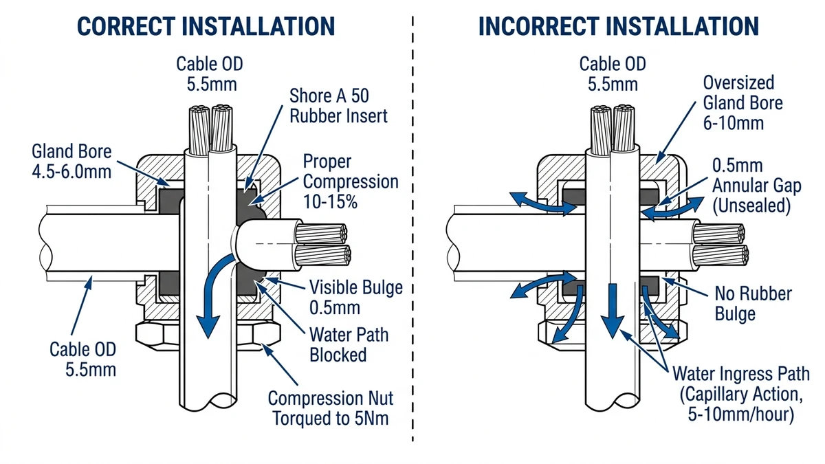
Insufficient compression leaves a 0.1-0.3 mm capillary gap. Water wicks through at 5-10 mm/hour—a 100 mm cable run from gland to terminal reaches the terminal in 10-20 hours of continuous rain.
Every unused knockout hole must be sealed. Wind pressure creates 50-100 Pa differential across the enclosure—enough to draw moisture-laden air through a 10 mm hole.
Blanking plugs (preferred): Nylon or brass plugs with O-ring seal. Torque to 3 Nm. The O-ring compresses 20-30% and maintains seal through thermal cycling.
Silicone sealant (temporary only): Apply 5 mm bead around plug threads. Replace with proper blanking plug within 6 months.
A 20 MW solar farm in Qinghai left knockout plugs hand-tight. Wind vibration (15-20 m/s gusts) loosened 40% of plugs within 8 months.
For surge protection device installation near cable entries to minimize inductance, see https://sinobreaker.com/surge-protection-device/.
[Expert Insight: Cable Gland Common Failures]
Install components in sequence to avoid re-work. Mounting a DC circuit breaker before routing cables forces you to disconnect and reconnect terminals—each connection cycle increases contact resistance by 5-10%.
1. Main busbars (positive/negative/ground): Torque M6 screws to 10 Nm, M8 screws to 15 Nm. Use thread-locking compound (Loctite 243 blue—removable with hand tools). Busbars carry 50-125 A—loose connections create 0.1-0.3 Ω resistance and dissipate 250-1200 W at full load.
2. DC circuit breakers: Mount on DIN rail. Connect to busbars with 10 mm² wire minimum—6 mm² wire overheats at >40 A continuous current. Torque breaker terminals to 2.5 Nm per manufacturer specification.
3. DC fuses: Insert into holders AFTER wiring is complete. Prevents accidental energization if someone connects the source before you finish.
4. Surge protection devices: Mount as close as possible to incoming cable entries—≤300 mm wire length. Every 100 mm of wire adds 100 nH inductance. At 1 kA/μs lightning current rise time, 300 nH inductance generates 300 V additional voltage.
For DC circuit breaker selection and terminal torque specifications, see https://sinobreaker.com/dc-circuit-breaker/.
Positive and negative conductors must run together—twisted pair or bundled with cable ties every 100 mm. Separating them by >50 mm creates a 200 nH/m inductance loop. During a fault, dI/dt reaches 1000 A/ms—the loop generates 200 V/m inductive voltage spike.
Maintain 10 mm clearance between AC and DC circuits (if mixed installation). Capacitive coupling between parallel conductors transfers transients from AC to DC side.
Use cable ties every 100 mm—loose wires vibrate and fatigue at terminals.
The enclosure ground point must connect to:
Use 16 mm² bare copper wire minimum; crimp with hex dies (not insulated ferrules). Torque ground lugs to 12 Nm—loose ground connections create 0.3-0.8 Ω resistance that allows transient voltages to reach 400V during lightning strikes.
Before closing the door, verify every seal point. A single 2 mm gap compromises the entire IP rating.
1. Wipe gasket surfaces with a lint-free cloth—remove any dust or wire insulation particles.
2. Inspect gasket for compression set: Press with thumb—should rebound within 2 seconds (if not, replace gasket).
3. Close door slowly: Listen for a “sucking” sound as gasket compresses—indicates proper seal.
4. Latch mechanism: Tighten until gasket compresses 2-3 mm (visible around perimeter)—over-tightening (>4 mm compression) causes permanent gasket deformation.
Apply silicone sealant (neutral cure, UV-resistant) only at these points:
Do NOT apply sealant:
– Over the door gasket (prevents future gasket replacement)
– Inside cable gland chambers (blocks drainage holes)
– On mounting fasteners (prevents future removal)
Cables exiting the bottom of the enclosure must have:
1. Drip loop: 100 mm minimum radius below gland entry—prevents water from running up cable into gland.
2. UV-resistant sleeving: Black corrugated conduit or heat-shrink tubing over first 500 mm of cable.
3. Strain relief: Secure cable to mounting surface 300 mm below enclosure—prevents wind-induced flexing at gland.
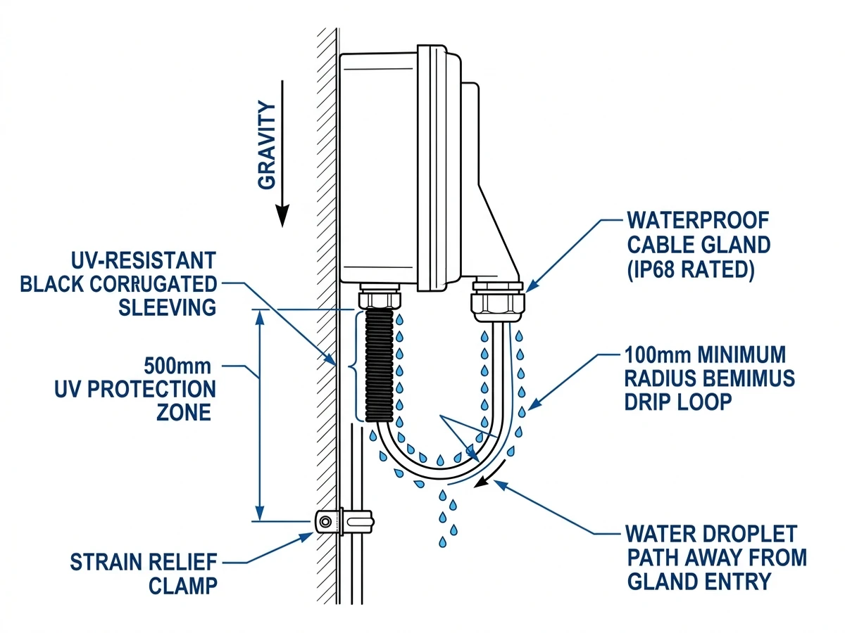
In a 5 MW carport PV system (Guangdong, 2022), cables without drip loops allowed rainwater to wick into glands—12 distribution boxes failed IP testing after one monsoon season.
Perform verification tests before energization. Finding a seal failure during commissioning takes 15 minutes to fix. Finding it after a rainstorm takes 4 hours and risks equipment damage.
Perform a simplified water ingress test:
1. Close and latch the door
2. Spray water from a garden hose (nozzle removed, 10 L/min flow) at all seams for 3 minutes
3. Open door and inspect: No water drop