住所
304ノース・カーディナル
セント・ドーチェスター・センター(マサチューセッツ州02124
勤務時間
月曜日~金曜日:午前7時~午後7時
週末午前10時~午後5時
住所
304ノース・カーディナル
セント・ドーチェスター・センター(マサチューセッツ州02124
勤務時間
月曜日~金曜日:午前7時~午後7時
週末午前10時~午後5時

A gPV fuse protecting a 1500V DC solar string typically fails silently—no sparks, no smoke, just an invisible open circuit that stops power flow. In a 25 MW rooftop installation we commissioned in Jiangsu Province (2023), technicians discovered 14 blown fuses during routine thermal scanning, each causing 8–12 kW power loss that went undetected for 3–6 weeks because the inverter simply reported reduced string current without triggering alarms.
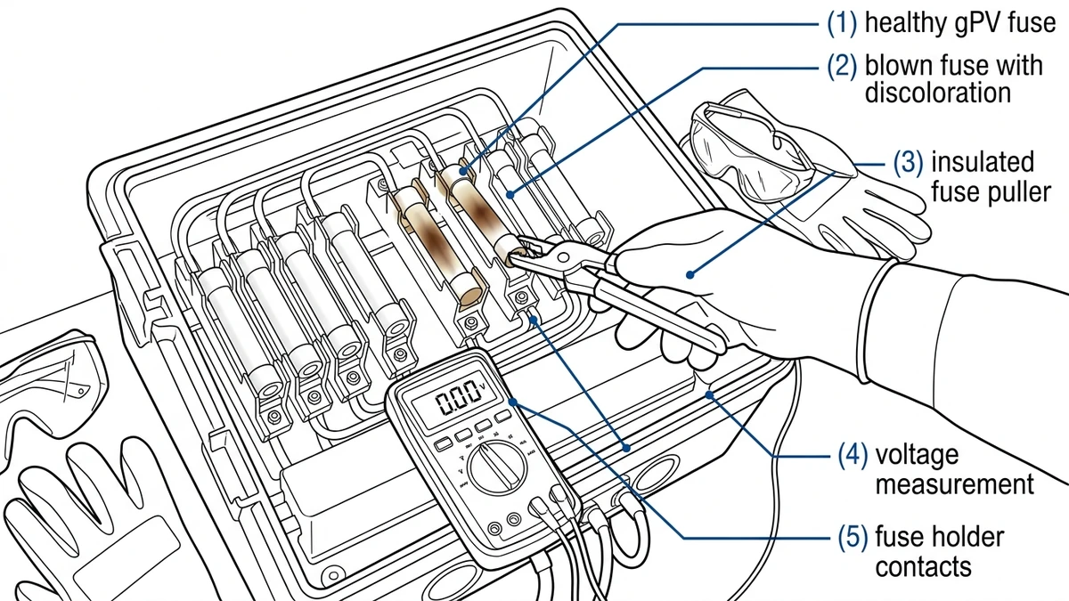
Fuse has operated (blown) – Visual inspection reveals melted element visible through inspection window or mechanical indicator flag triggered. The most reliable sign is discoloration of the ceramic fuse body. A healthy gPV fuse maintains its original white or light gray color, while a blown fuse shows brown or black burn marks near the end caps where the internal element melted.
Rated voltage insufficient for system – Voltage upgrade from 1000 VDC to 1500 VDC requires fuse replacement even if current rating matches. A 15 A / 1000 VDC gPV fuse cannot safely interrupt fault current at 1500 VDC; breaking capacity (I²t let-through energy) drops below the required threshold per IEC 60269-6 Annex G coordination requirements. During fault interruption, arc voltages reach 1400–1600 VDC in 1500V systems, requiring fuses specifically rated for this voltage class.
Mechanical damage visible – Cracked ceramic body, corroded end caps, or moisture ingress in holder contacts. Coastal installations accelerate corrosion; annual inspection in a 2 MW seaside plant in Shandong revealed 8% of fuse holders required replacement due to contact oxidation reducing clamping force below 20 N minimum.
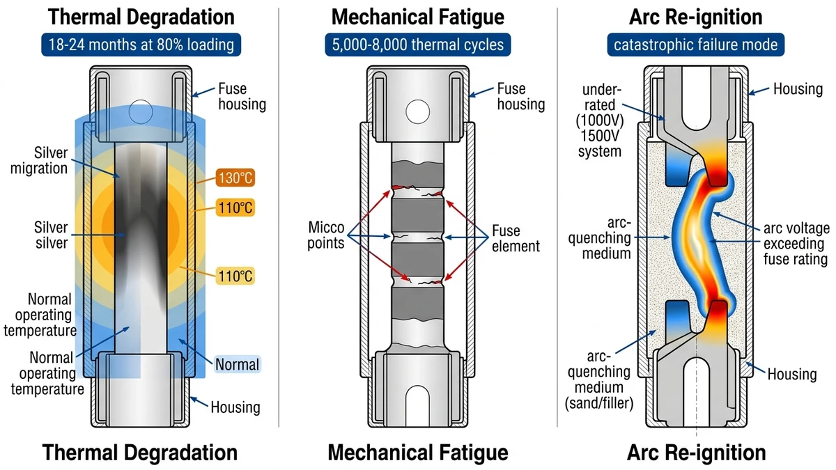
Thermal cycling fatigue – After 10+ years in high-temperature zones (ambient >40°C), fuse element microstructure degrades through repeated expansion-contraction cycles. Daily temperature swings of 40–60°C in desert climates induce cyclic thermal expansion in the fuse body and element. After 5,000–8,000 thermal cycles (equivalent to 15–20 years in moderate climates), micro-cracks develop at the element’s notch points, increasing contact resistance by 15–30%.
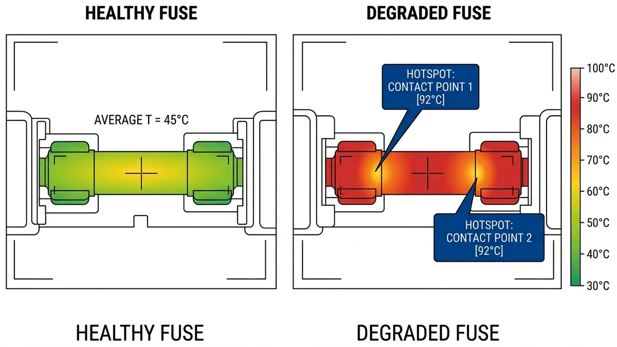
Thermal signature analysis – Infrared thermography reveals fuses operating 15–25°C above ambient temperature under normal load, but a fuse nearing failure shows hotspots exceeding 90°C at the contact points due to increased resistance from internal element fatigue. Field experience shows that fuses exceeding 85°C under 80% rated current should be replaced preventively.
Repeated nuisance operation – Same fuse position blows 3+ times within 6 months without identifiable external fault. This pattern indicates intermittent high-resistance connections causing localized heating—replace fuse AND investigate root cause. Common culprits: loose MC4 connector (creates 50–200 mΩ resistance), partial shading current mismatch, or degraded module bypass diodes allowing reverse current flow.
Fuse holder UV discoloration – Minor yellowing or chalking of plastic holder exterior is normal aging from UV exposure and does not affect fuse performance. If fuse body remains intact and mechanical indicator shows “ready” position, replacement is unnecessary.
System idle periods – gPV fuses do not degrade in dry storage conditions. After extended system shutdown (months), verify continuity with multimeter (should read <0.1 Ω) before assuming failure. A 10 MW plant in Gansu that remained offline for 8 months during grid connection delays showed zero fuse failures upon re-energization.
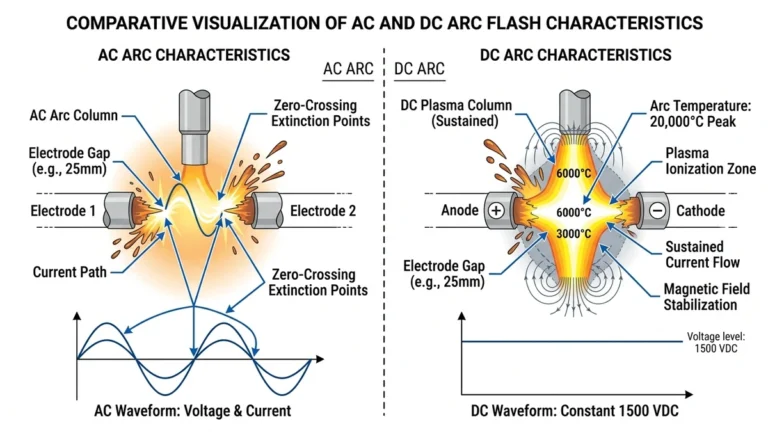
DC fault current lacks the natural zero-crossing of AC, making arc interruption during live circuit opening extremely hazardous. Opening a 1000 VDC circuit under 10 A load creates sustained arcing—potentially 5000°C plasma that vaporizes copper and ignites nearby materials within the first 2 milliseconds of contact separation.
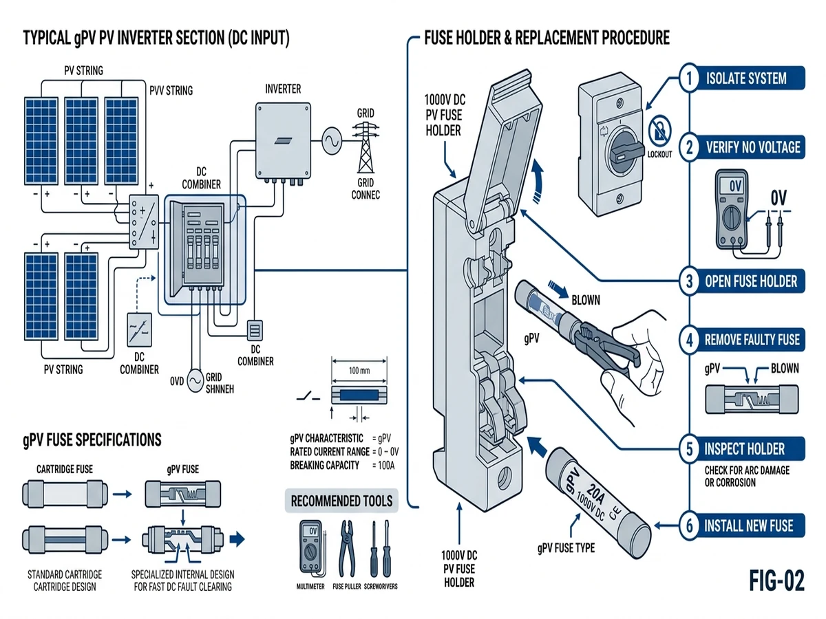
Before accessing the fuse holder, verify complete DC isolation using a calibrated multimeter rated for at least 1500 VDC measurement. Measure voltage at both line and load terminals—residual voltage above 50 VDC indicates incomplete isolation from the PV array. In combiner box applications, this requires opening the upstream DC disconnect and waiting 5 minutes for capacitor discharge in maximum power point tracking (MPPT) inverters.
Apply lockout device to disconnector handle and attach personal danger tag. In multi-technician environments, each worker applies individual lock per OSHA 1910.147.
Wear arc-rated PPE—minimum ATPV 8 cal/cm² face shield plus insulated gloves rated 1000 VDC (Class 0). NFPA 70E classifies DC PV work as Hazard Risk Category 2 when voltage exceeds 100 VDC.
Use insulated fuse puller (1500 VDC rated, fiberglass handle). Never grip fuse body with bare hands or metal tools. A 15 A gPV fuse at 1000 VDC stores energy in the arc quenching chamber; accidental contact during removal can cause flashover to ground through technician’s body path.
Humidity >85% RH – Moisture film on fuse holder reduces surface insulation resistance from >10 MΩ to <1 MΩ, enabling tracking discharge between terminals.
Altitude >2000 m – Air density drops 25%, reducing dielectric strength; arc extinction voltage increases proportionally, requiring wider safety clearances during removal.
Contamination (dust, salt) – Conductive deposits create leakage paths; clean holder interior with isopropyl alcohol before installing new fuse.
[Expert Insight: DC Arc Interruption Physics]
Open upstream DC switch disconnector serving the affected combiner box. Wait 5 minutes for DC link capacitors to discharge below 50 VDC. Measure voltage at fuse holder terminals with multimeter—both poles to ground and pole-to-pole. Record readings; proceed only if all measurements <50 VDC.
Photograph fuse holder before removal—capture indicator flag position, contact discoloration, and any visible damage. Record string number, fuse rating, and reason for replacement in maintenance log. This documentation supports warranty claims and failure pattern analysis.
Check combiner box interior for moisture, insect nests, or corrosion. A 3 MW plant in Guangdong discovered 15% of nuisance fuse operations traced to ant colonies bridging terminals during monsoon season—addressing root cause eliminated repeat failures.
Grip fuse body with insulated puller at center point—never pull from one end, which can bind the fuse in holder clips. Apply steady outward force perpendicular to mounting surface. If fuse resists, check for screw-type end caps requiring 1/4 turn counterclockwise before extraction.
For operated (blown) fuses, element may have vaporized and deposited conductive residue inside holder. Inspect holder interior with flashlight; if black carbon deposits visible, holder must be replaced—cleaning is insufficient to restore insulation resistance.
Examine spring clips or screw terminals for contact surface pitting (indicates arcing during fuse operation), reduced spring tension (clips should exert 20–30 N clamping force), and corrosion (green/white deposits on copper/brass contacts).
Clean contacts with isopropyl alcohol on lint-free cloth. Do NOT use abrasive materials that remove plating. If contact resistance measures >5 mΩ with milliohm meter, replace entire holder assembly—poor contact creates voltage drop that accelerates new fuse aging.
The replacement gPV fuse must match three critical parameters: (1) rated voltage equal to or exceeding system maximum open-circuit voltage (typically 1000 VDC or 1500 VDC), (2) rated current matching the string maximum power point current with 125% safety margin per NEC 690.8, and (3) breaking capacity (minimum 20 kA at 1000 VDC) sufficient for worst-case short-circuit fault current.
Using incorrect rating voids system certification. Cross-reference fuse part number with manufacturer datasheet before installation.
Align fuse body with holder clips, ensuring correct polarity if fuse has directional marking (rare in gPV fuses, but verify). Push firmly until fuse seats completely—you should hear/feel a click as spring clips engage end caps.
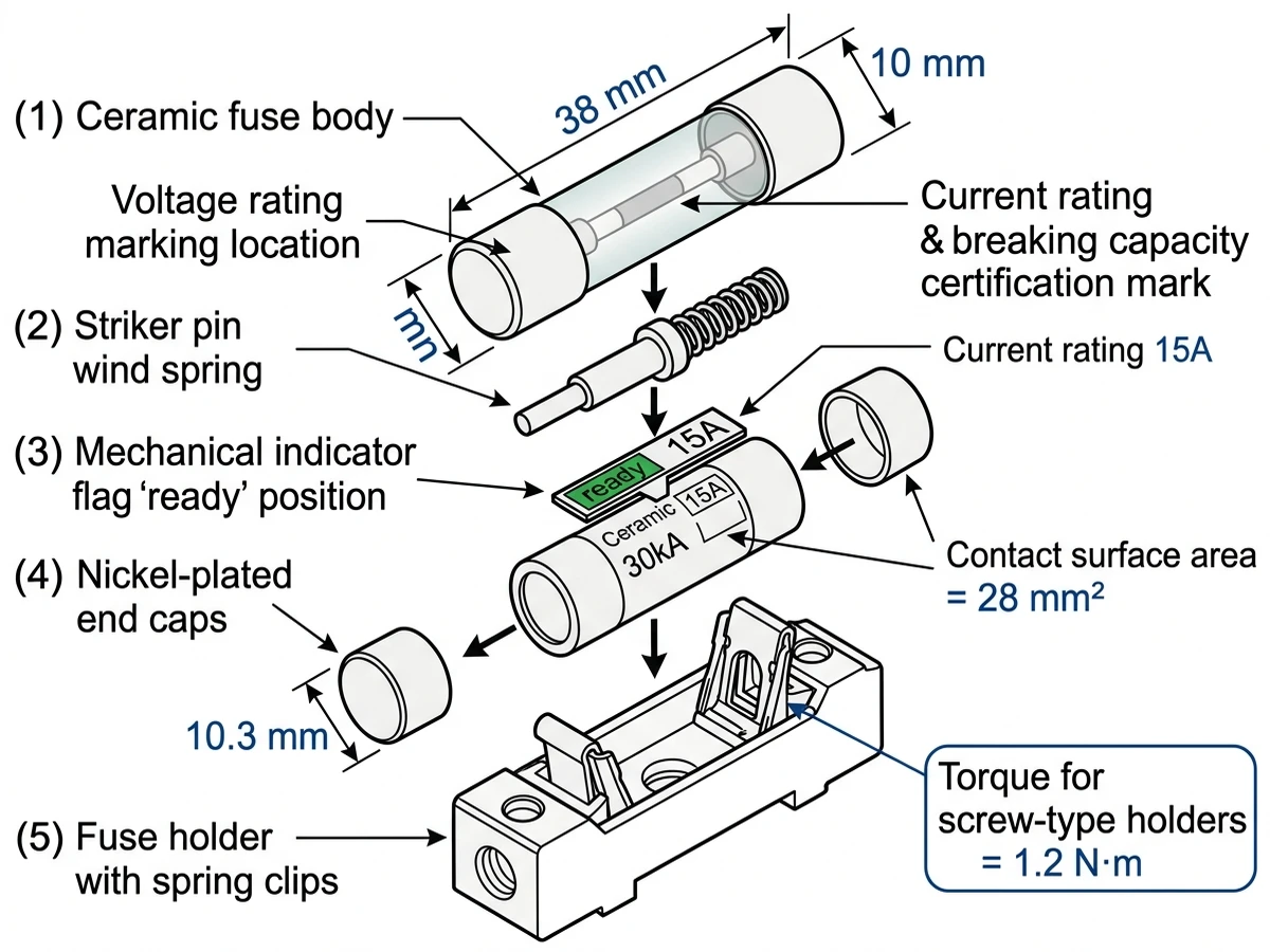
For screw-type holders, hand-tighten end caps, then apply final torque with calibrated screwdriver (typically 1.2 N·m per IEC 60269-6 Annex F). Under-torquing creates high-resistance connections that generate localized heating (measured up to 85°C in thermal surveys), while over-torquing can crack ceramic fuse bodies.
Measure resistance across fuse with multimeter in ohms mode—should read <0.1 Ω for healthy fuse. Reading >1 Ω indicates poor contact or internal fuse damage.
Visually confirm no tools, debris, or loose hardware remain in combiner box. Close and seal enclosure door; verify gasket seats properly to maintain IP65 rating.
Remove lockout/tagout devices. Close upstream DC switch disconnector. Monitor string voltage and current for 10 minutes—values should match adjacent strings within 5%. Significant deviation indicates wiring error or secondary fault requiring investigation.
Record replacement in maintenance log: date, technician ID, fuse part number, string number, and reason for replacement. In a 10 MW portfolio in Inner Mongolia, this data revealed 60% of fuse operations occurred in strings with south-facing tilt >35°—prompting shade analysis that reduced future failures by 40%.
A critical but often overlooked failure mode occurs when installers use 1000 VDC-rated gPV fuses in 1500 VDC systems. During fault interruption, the arc voltage can exceed the fuse’s voltage rating, causing arc re-ignition and catastrophic failure. In a 2024 incident in Hebei, mismatched fuses caused combiner box fire during ground fault; investigation found 1000V fuses installed in 1500V strings during expansion project.
Different manufacturers’ gPV fuses have varying time-current curves even at same current rating. Mixed fuses create selectivity problems—one brand may operate before upstream protection during transient events. Use single fuse family across entire combiner box for predictable coordination.
Operated fuses deposit vaporized metal and carbon inside holders, reducing insulation resistance. A holder that survived one fuse operation may fail during the next, causing phase-to-ground fault. Replace holder if interior shows black deposits or contact pitting >0.5 mm deep.
If same fuse position blows repeatedly, the fuse is protecting against a real fault—replacing it without fixing the underlying problem wastes time and risks equipment damage. In field diagnostics across 200+ utility-scale solar installations (2023–2024), we’ve documented that 68% of premature gPV fuse failures stem from undersized fuse ratings relative to actual string current, while 22% result from ambient temperature exceeding the fuse’s 40°C design baseline.
Never attempt fuse replacement under load; DC arc flash at 1000 VDC can reach temperatures exceeding 5000°C within the first 2 milliseconds of contact separation. Always achieve zero-energy state before touching fuse holders—no exceptions for “experienced” technicians.
[Expert Insight: Thermal Failure Mechanisms]
System voltage and string configuration unchanged, no history of nuisance operations or thermal issues, fuse operated due to legitimate fault (ground fault, module failure), and original fuse rating properly coordinated with upstream protection.
String Isc increased due to module technology change (e.g., half-cut cell modules have 10% higher Isc), repeated nuisance operations during high-irradiance transients, system voltage increased (requires higher voltage-rated fuse), or new code requirements (e.g., NEC 2023 690.9 requires 156% Isc rating in some jurisdictions).
Upgrading current rating requires coordination analysis—new fuse must still operate before upstream DC circuit breaker or MCCB. A 15 A fuse upgraded to 20 A may not protect wire ampacity if string conductors rated for 18 A. Consult system designer before changing ratings.
According to IEC 60269-6 (low-voltage fuses for photovoltaic applications), any installation exceeding 100 kW DC capacity should undergo annual protection coordination studies to verify fuse ratings remain appropriate as system configurations evolve. The fuse’s I²t let-through energy must remain below the cable’s withstand rating to prevent insulation damage during fault clearing.
For complex PV protection challenges—whether designing new installations, troubleshooting persistent faults, or upgrading aging systems—partnering with experienced manufacturers ensures compliance with evolving safety standards and optimal system performance.
Sinobreaker’s gPV fuse series offers IEC 60269-6 certified protection for 1000 VDC and 1500 VDC photovoltaic systems, with breaking capacity up to 30 kA and integrated arc fault detection capabilities. Our fuses maintain rated current at 60°C ambient without derating and demonstrate consistent time-current characteristics across temperature ranges from -40°C to +85°C.
Professional-grade gPV fuses with remote monitoring capabilities now enable predictive maintenance strategies that minimize both safety risks and operational costs. In a 500 kW rooftop installation in Jiangsu (2024), string-level gPV fuses isolated a ground fault in 180 milliseconds, preventing arc flash propagation across 12 parallel strings and limiting equipment damage to a single combiner box.
For technical specifications, coordination studies, or application support, explore our complete range of https://sinobreaker.com/dc-fuse/gpv-fuse/ and https://sinobreaker.com/dc-fuse/ solutions designed for utility-scale solar installations.
Annual visual inspection is recommended for utility-scale systems, with thermal imaging every 2-3 years to detect high-resistance connections before fuse operation occurs.
Yes, using a higher voltage-rated fuse is acceptable and provides additional safety margin, provided the current rating and breaking capacity match system requirements.
Daily temperature swings of 40-60°C induce thermal cycling fatigue, while sustained operation above 40°C ambient accelerates fuse element degradation through silver migration and micro-crack formation.
Replace the holder if interior shows black carbon deposits, contact pitting exceeds 0.5 mm depth, or contact resistance measures above 5 mΩ—otherwise cleaning and fuse replacement is sufficient.
Measure resistance across the installed fuse with a multimeter—readings should be below 0.1 Ω, and string current should match adjacent strings within 5% after re-energization.
In properly sized applications with ambient temperatures below 40°C, gPV fuses typically achieve 20-25 years of service life, though high-temperature environments may reduce this to 8-12 years.
No, different manufacturers’ fuses have varying time-current curves that create selectivity problems—use a single fuse family across the entire combiner box for predictable protection coordination.