住所
304ノース・カーディナル
セント・ドーチェスター・センター(マサチューセッツ州02124
勤務時間
月曜日~金曜日:午前7時~午後7時
週末午前10時~午後5時
住所
304ノース・カーディナル
セント・ドーチェスター・センター(マサチューセッツ州02124
勤務時間
月曜日~金曜日:午前7時~午後7時
週末午前10時~午後5時

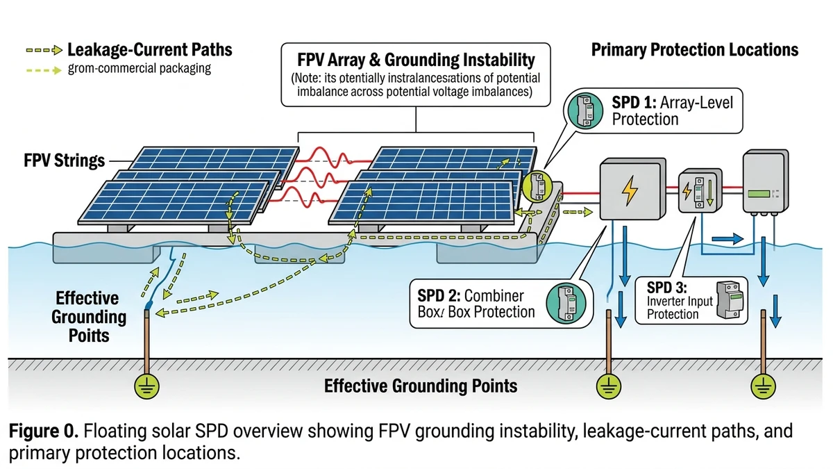
Floating photovoltaic (FPV) systems change the electrical reference conditions that DC surge protection depends on, so SPD design cannot simply be copied from ground-mount projects.
On a fixed ground-mount system, the grounding electrode is stable, soil resistivity is measurable, and the equipotential bonding network stays intact. On a floating platform, those conditions do not hold. The pontoon structure shifts with water level and wave action, mechanical connections loosen over time, and the water body can act as a low-impedance return path that bypasses the intended grounding circuit.
IEC 62548-1 governs PV array design requirements including protective earthing, but it does not give project-level guidance tailored to floating installations. Engineers often have to adapt land-based rules to a different environment.
In a 35 MW FPV installation on a reservoir in Anhui Province (2023), commissioning engineers measured ground-fault leakage currents exceeding 300 mA during rain events—roughly 6× the threshold that would trip a standard residual current device on a comparable land-based array. The root cause was intermittent bonding continuity across pontoon joints, which created floating potential differences of up to 50 V between module frames and the water surface.
When the grounding reference is unstable, an SPD’s clamping voltage (Up)—typically rated at ≤2.0 kV for Type 2 devices per IEC 61643-11—is measured against a reference that may shift by tens of volts in real time. That degrades protection accuracy and can cause nuisance disconnections or let damaging overvoltage reach inverter inputs.
This directly affects how DC SPDs should be selected and installed in FPV systems. For a broader grounding and lightning protection framework, the solar panel lightning protection and grounding guide covers the foundational principles that FPV engineers need to adapt.
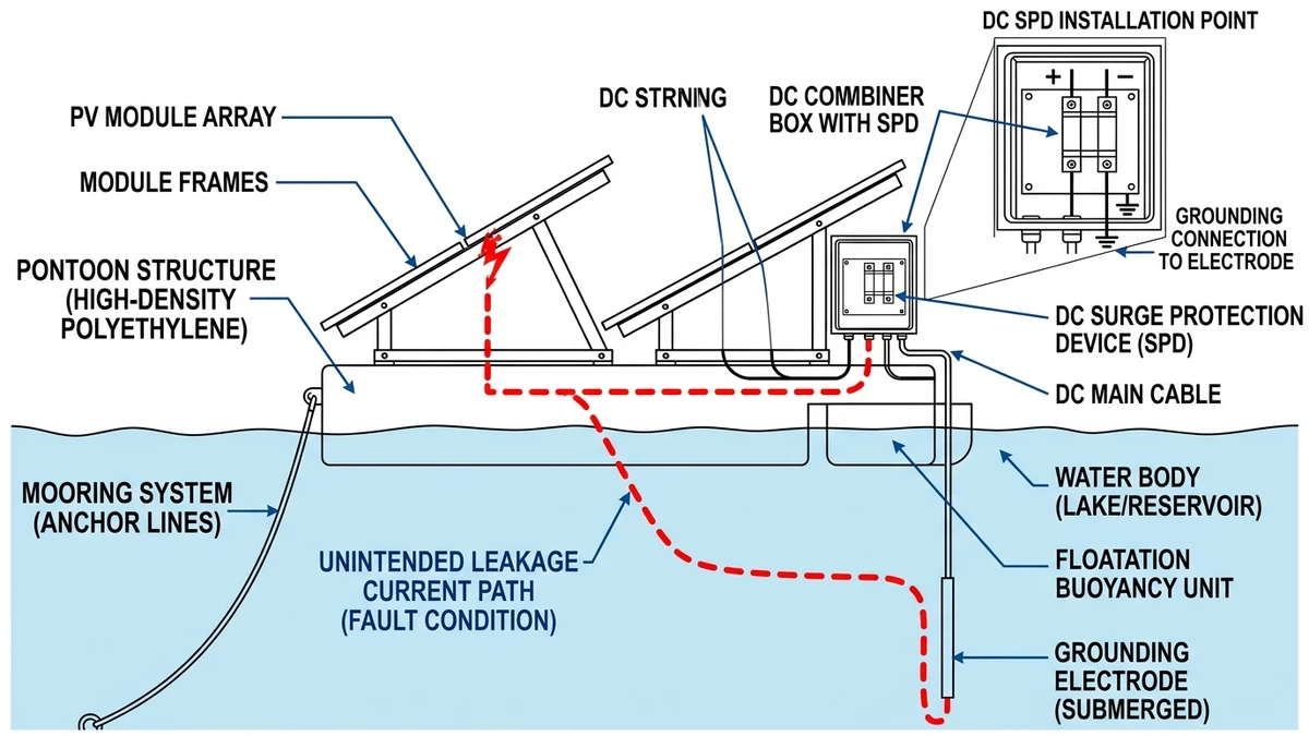
Every PV module in an FPV array sits close to water, creating distributed capacitance between the module’s active cell layer and the water surface—typically 50–200 nF per module depending on frame design, laminate thickness, and water conductivity. In a 1500 VDC string, this distributed capacitance forms a continuous leakage path to the floating structure and, through it, to the water body below.
The leakage current spreads across the wetted surface area of the array, with each module contributing a small but additive current component. In a 2 MW FPV block with more than 4,000 modules, aggregate leakage current can reach 500–800 mA under normal operating conditions.
HDPE pontoons are nominally non-conductive, but metallic interconnects, cable trays, module mounting rails, and fasteners create a partially conductive mesh across the platform. This mesh acts as an unintended equipotential plane—not a true ground reference, but a floating conductor coupled capacitively to both the DC string voltage and the water body.
At a 35 MW FPV installation in Anhui Province (2023), pontoon-to-water potential differences exceeded 120 V AC common-mode during afternoon peak generation, causing nuisance tripping of string-level insulation monitoring units before the grounding topology was revised.
This means surge energy from a nearby lightning strike can propagate through two paths at once, arriving at the surge protection device from both the DC line side and the PE side. Standard SPD coordination methods developed for ground-mount systems do not account for that bidirectional injection. For a broader treatment of SPD selection principles, the DC SPD selection guide for solar systems covers the baseline methodology that FPV designs must adapt.
[Expert Insight]
– Measure insulation resistance and leakage behavior during both dry midday and rain-event conditions; FPV faults often appear only when humidity and surface wetting increase.
– Do not assume plastic pontoons isolate the array electrically; test the entire metal hardware network as one coupled structure.
– Review common-mode voltage trends at inverter inputs, not just line-to-line values, when investigating unexplained SPD operation.
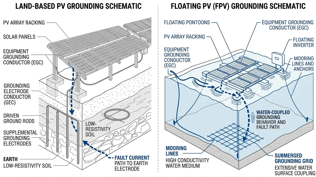
On a conventional ground-mount PV system, a copper earth electrode driven into soil provides a relatively stable fault path, typically under 10 Ω. FPV platforms replace that with a floating structure where the effective reference depends heavily on water conductivity, which can vary from roughly 0.05 mS/cm in freshwater reservoirs to over 50 mS/cm at brackish or coastal sites. That range affects fault-loop impedance and changes how SPD clamping voltage performs during real surge events.
A 50 MW FPV installation in Anhui Province (2023) encountered repeated SPD nuisance tripping during monsoon season. Post-analysis found that rising water conductivity had lowered effective ground impedance enough to push leakage current above the SPD’s follow-current threshold—a failure mode unlikely on a dry-soil ground-mount site with stable earth resistance.
| パラメータ | Land-Based PV | Floating PV (FPV) |
|---|---|---|
| Earth electrode resistance | 4–10 Ω (stable soil) | 0.5–50 Ω (water-dependent) |
| SPD protection level (Up) | ≤ 2.5 kV (IEC 61643-11) | ≤ 2.0 kV recommended |
| Enclosure ingress protection | 最小IP54 | 最小IP66 |
| Corrosion environment | C2–C3 (IEC 60068-2-52) | C4–C5M (marine/humid) |
| SPD discharge current (In) | 5–10 kA (Type 2) | 10–20 kA (Type 1+2 combined) |
| Follow current extinguishing | Standard MOV | Enhanced, low-leakage MOV |
| Grounding conductor material | Copper, standard | Tinned copper or stainless |
| Inspection interval | 年間 | Quarterly (corrosion-driven) |
These differences are not arbitrary. FPV structures see more variable reference potential, higher humidity stress, and more aggressive corrosion than land systems, so conservative land-based SPD sizing often becomes undersizing in practice. For a deeper look at how SPD type classification maps to these conditions, the DC SPD type selection guide covers Type 1 vs. Type 2 application logic in detail.
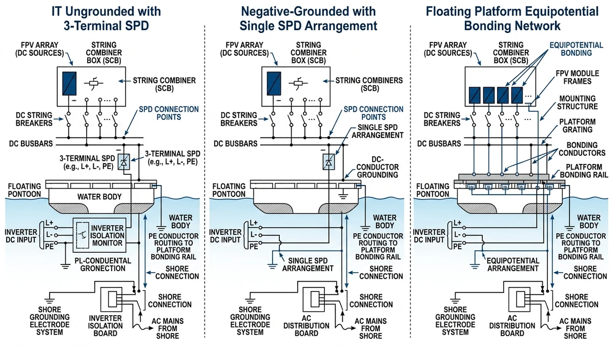
Most utility-scale FPV projects in China and Southeast Asia use an ungrounded IT topology, where neither the positive nor negative DC bus is bonded to earth. This helps reduce galvanic corrosion risk, but it also means surge energy has no simple low-impedance return path.
In this arrangement, SPDs should be installed in a 3-terminal configuration: positive-to-PE, negative-to-PE, and positive-to-negative, with each leg rated for the full open-circuit voltage (Voc). For a 1500 VDC string system, that typically means devices with Up ≤ 2.0 kV and Iimp ≥ 12.5 kA per IEC 61643-11 Type 1 classification.
In a 62 MW FPV installation in Anhui Province (2023), switching from 2-terminal to 3-terminal SPD wiring in IT-configured combiner boxes reduced residual voltage at inverter DC inputs by about 35%, bringing protection levels within inverter MCOV tolerances.
Some string inverter deployments use a negative-grounded configuration, where the negative rail is bonded to the platform’s equipotential bonding network. In that case, SPDs connect positive-to-PE only, which simplifies wiring but requires the PE conductor to carry full surge current. The PE path should be sized at not less than 16 mm² copper to limit resistive voltage rise that would otherwise degrade clamping performance.
Regardless of topology, SPDs should be placed at each transition point where cable routing changes from array to inverter—typically at the PVコンバイナーボックス and again at the DC distribution enclosure. For FPV, a third placement at the shore-side cable landing point is strongly recommended because the overwater cable run behaves like an antenna for induced lightning surges. Refer to the DC SPD wiring diagram guide for conductor sizing and terminal torque specifications by topology.
[Expert Insight]
– Keep SPD connection leads as short and straight as possible; extra lead length adds inductive voltage drop and directly worsens residual voltage during a surge.
– At shore landing points, bond and protect both power and communication circuits together to avoid transferred surges between systems.
– If the plant uses IT monitoring, verify SPD compatibility with insulation monitoring devices before commissioning, not after nuisance alarms begin.
Floating arrays sit at the air-water interface, where relative humidity often stays above 85% RH. Unlike rooftop or ground-mount sites where enclosures dry out between rain events, FPV combiner boxes and DC distribution boxes can experience near-continuous condensation cycling. This accelerates MOV degradation through moisture ingress at terminal connections, progressively increasing leakage current and lowering the clamping threshold.
IEC 61643-11 requires SPDs to pass humidity endurance testing at 93% RH, but that laboratory test covers weeks, not the multi-year service life expected on a reservoir installation.
A 35 MW FPV project on a reservoir in Anhui Province (2023) documented measurable grounding-resistance drift within 18 months of commissioning. Grounding conductors bonded to aluminum float frames using standard copper lugs showed contact-resistance increases from 0.05 Ω to over 1.2 Ω. That 24× rise effectively compromised the SPD discharge path.
When a Type 2 SPD rated for 20 kA (8/20 μs) cannot discharge to a low-impedance path, the effective protection level rises beyond what many 1000 VDC inverter input stages can tolerate. For projects using gPV string fuses and PV combiner boxes in floating configurations, grounding integrity checks should be scheduled at 6-month intervals rather than annual intervals typical of land-based plants.
Pontoon movement on open-water reservoirs introduces cyclic stress on conduit entries and cable glands, which are common ingress failure points. Wind-driven wave action on a 500 m fetch can generate pontoon displacement of 80–120 mm at 0.3–0.8 Hz, enough to work-harden and eventually crack compression fittings intended for static installation.
This is why FPV SPD enclosures and gland systems should be chosen as mechanical components, not only electrical ones.
In a 35 MW FPV installation on a reservoir in Anhui Province (2023), SPDs without IT-system compatibility triggered nuisance disconnections during insulation monitoring events, causing repeated inverter shutdowns until the devices were replaced with floating-reference-rated units.
Before issuing a purchase order, confirm these against the project electrical design:
A 60 MW FPV project on Hongze Lake, Jiangsu (2023), reported SPD failure rates three times higher than comparable ground-mount sites when standard IP54 enclosures were used. Switching to IP67-rated units with isolated ground terminals reduced nuisance tripping by roughly 70% over the following 12 months.
For a full overview of compatible DC overcurrent protection, the 直流遮断器 series page covers rated parameters and configuration options. The DC SPD wiring and grounding reference walks through installation-level decisions in detail. For authoritative grounding methodology, IEC 62305-3 remains the primary external reference for lightning protection and earthing design.
Contact the Sinobreaker technical team with the site keraunic level, string voltage, and pontoon material to get a component-level SPD specification within one working day.
Because the modules and support structure are closely coupled to the water surface, the array develops distributed capacitance that creates larger common-mode leakage paths.
They are typically installed at the combiner box and DC distribution point, with an additional unit at the shore-side cable landing point for long overwater runs.
Not always. FPV projects often need higher discharge capability, better enclosure protection, and compatibility with IT or floating-reference systems.
IP65 is the practical minimum, while IP67 is preferred in splash zones or where the enclosure sits close to the waterline.
Corrosion raises connection resistance in the discharge path, which can increase residual voltage and reduce the SPD’s real protective effect during a surge.
No. The SPD should connect to a designed equipotential bonding network on the floating structure rather than relying on direct water contact or anchor chains.
Floating installations generally benefit from more frequent checks than land plants, especially for bonding integrity, enclosure sealing, and corrosion at terminals.


