住所
304ノース・カーディナル
セント・ドーチェスター・センター(マサチューセッツ州02124
勤務時間
月曜日~金曜日:午前7時~午後7時
週末午前10時~午後5時
住所
304ノース・カーディナル
セント・ドーチェスター・センター(マサチューセッツ州02124
勤務時間
月曜日~金曜日:午前7時~午後7時
週末午前10時~午後5時

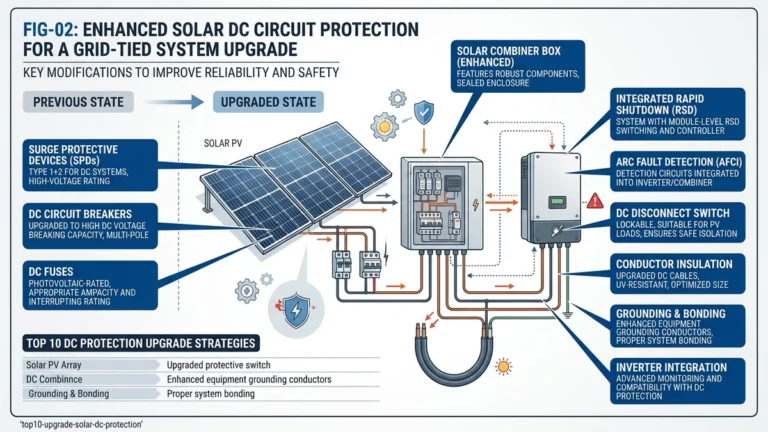
Solar DC protection is being redefined by higher operating voltages, stricter compliance demands, and better fault-detection technology. For designers and EPC teams, device selection can no longer be based on legacy 1000 VDC assumptions or generic overcurrent rules.
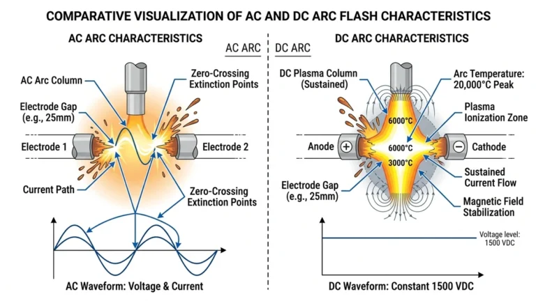
The move to 1500 VDC string architecture is the biggest hardware driver. At 1500 V, prospective short-circuit current at a combiner bus can reach 20–30 kA, and DC arc energy rises with voltage, so a breaker or fuse rated for 1000 VDC may not interrupt reliably under the same conditions. IEC 60947-2 governs breaking-capacity requirements for DC circuit breakers in industrial and PV use, and components must be rated for the actual operating voltage rather than informally derated from AC values.
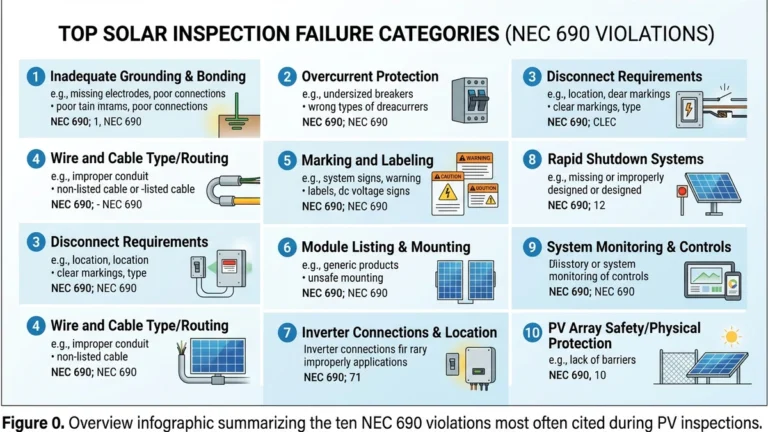
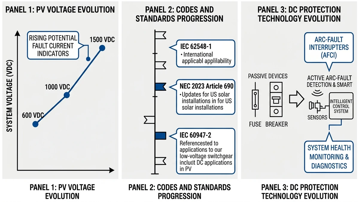
Codes are tightening at the same time hardware demands are increasing. IEC 62548-1, NEC 2023 Article 690, and parallel regional standards all push designers toward faster fault isolation, better documentation, and more precise device matching.
For PV arrays with parallel strings, reverse-current risk is a central compliance issue. Where reverse current can exceed allowable limits, string overcurrent protection becomes mandatory. In practice, that increasingly means specifying gPV-rated fuses designed for photovoltaic duty under IEC 60269-6, instead of using general-purpose DC fuses that lack PV-specific clearing behavior.
Overcurrent protection still matters, but it cannot detect every dangerous condition. High-impedance DC arc faults often stay below fuse or breaker trip thresholds long enough to heat connectors, degrade insulation, and ignite nearby materials.
Modern string-level monitoring built into protective assemblies uses high-frequency signature analysis to identify arc behavior before thermal damage spreads. That shift from passive protection to active detection is one of the clearest signs that legacy protection stacks are aging out of utility-scale PV.
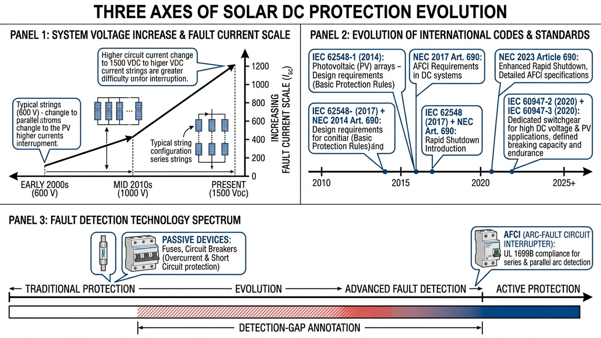
The shift from 1000 VDC to 1500 VDC is now the standard architecture for most utility-scale and many large commercial installations. Higher voltage reduces conductor size requirements and lowers combiner-box count, which can cut balance-of-system cost by about 10–15%. The tradeoff is that every protective device now has to interrupt fault current at 1500 VDC, where arc extinction is much more difficult.
Protective devices rated for 1500 VDC must meet IEC 60947-2 Annex M for DC breaking capacity and arc interruption.
As more markets align around similar PV safety principles, compliance has become a specification driver rather than a late-stage review item. The main effect is tighter control over overcurrent sizing, fault isolation methods, and product certification.
| スタンダード | Region | Key DC Protection Requirement |
|---|---|---|
| IEC 62548-1 | Global | String overcurrent protection, reverse current limits |
| NEC第690条 | USA | AFCI required for PV systems ≥ 80V DC |
| IEC 60947-2 附属書 M | Global | DC breaking capacity for MCBs at 1000/1500 VDC |
| AS/NZS 5033 | AU/NZ | Array wiring and overcurrent device ratings |
One clear implication is that gPV-rated fuses are now the default requirement in most jurisdictions when string protection is needed. They are tested specifically for photovoltaic fault profiles and remain one of the simplest ways to avoid code and insurer objections during design review.
[Expert Insight]
– Check reverse-current exposure before selecting fuse size; adding strings later can change whether string fusing is mandatory.
– Ask suppliers for standard-specific test reports, not only a datasheet claim of “IEC compliant.”
– Verify whether local fire or insurer rules impose AFCI requirements even when national code language is less explicit.
String-level AFCI is moving from premium feature to mainstream requirement. Series arcs caused by connector wear, loose terminations, or micro-cracked conductors are difficult to catch because current often remains below the trip point of conventional protective devices.
Under NFPA 70 (NEC) 2023, AFCI protection is required for PV systems above 80 VDC in the US. Modern AFCI-integrated devices use high-frequency current analysis to separate true arc signatures from normal switching transients, with response times often in the 2.5–4 second range. That makes AFCI a complement to overcurrent protection, not a replacement for it.
Fuse selectivity means the protective device nearest the fault opens first while upstream circuits remain energized. In PV combiner design, that depends on I²t coordination: the let-through energy of the downstream fuse must remain below the pre-arcing I²t of the upstream fuse across the expected fault range.
A commonly used field rule is to maintain at least a 1.6:1 I²t margin between adjacent protection levels when coordinating PV fuse stages. When that margin narrows, a single-string fault can trigger an upstream fuse and take healthy strings offline as collateral damage.
Bifacial gain raises effective short-circuit current, which means 2022-era fuse tables often understate the rating needed for current module generations.

The table below reflects the sizing shift driven by bifacial gain factors of 1.10–1.15 under IEC 62548-1 string protection rules, which require fuse ratings ≥ 1.4 × Isc per string.
| Module Type | Isc (A) | Bifacial Gain Factor | Adjusted Isc (A) | Min. Fuse Rating (A) | I²t Ratio to Combiner Fuse |
|---|---|---|---|---|---|
| Monofacial 550 W | 13.9 | 1.00 | 13.9 | 15 A (gPV) | ≥ 1.6:1 |
| Bifacial 650 W | 14.8 | 1.10 | 16.3 | 20 A (gPV) | ≥ 1.6:1 |
| Bifacial 700 W | 15.6 | 1.12 | 17.5 | 20–25 A (gPV) | ≥ 1.6:1 |
| Bifacial 720 W (HJT) | 16.1 | 1.15 | 18.5 | 25 A (gPV) | ≥ 1.6:1 |
正しい選択 gPV fuse starts with module Isc, but it should end with a coordination check against combiner-level devices. The DC fuse selection guide is useful for reviewing voltage class, current rating, and breaking capacity together before locking a BOM.
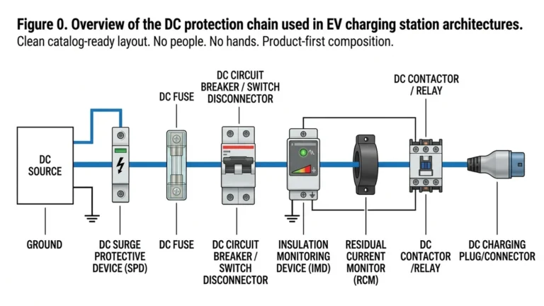
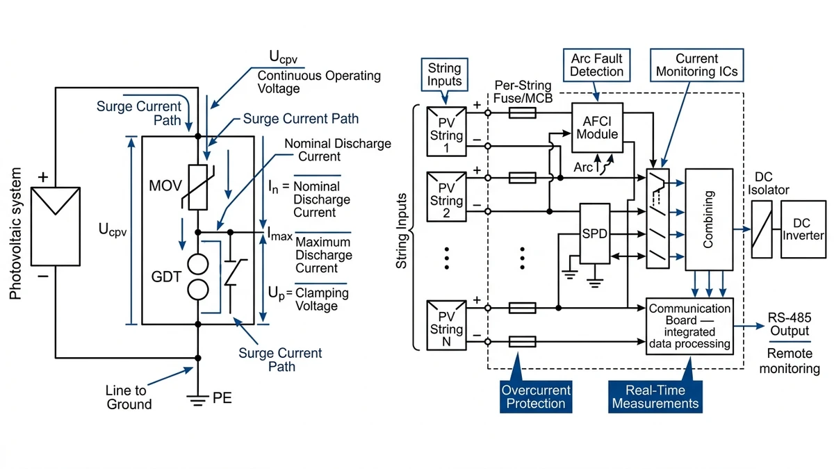
A DC SPD limits transient overvoltage by diverting surge current through MOV or spark-gap elements so downstream equipment sees a lower residual voltage. In PV design, engineers generally review Ucpv, discharge current, clamping level, response time, and SCCR before approving a device. For reference on surge concepts and waveform testing, IEC maintains a standards overview at https://www.iec.ch.
| パラメータ | Typical Range | Unit | 備考 |
|---|---|---|---|
| Maximum continuous operating voltage (Ucpv) | 1000–1500 | 仮想装置 | Must exceed open-circuit string voltage × 1.25 |
| Nominal discharge current (In) | 5–20 | kA | Per IEC 61643-11 8/20 µs waveform |
| Maximum discharge current (Imax) | 20–40 | kA | Single-impulse rating |
| Voltage protection level (Up) | ≤ 2.5–4.0 | kV | Lower is better; must coordinate with inverter MCOV |
| 応答時間 | < 25 | ns | MOV-based devices |
| Short-circuit current rating (SCCR) | 25–50 | kA | Must match prospective fault current at installation point |
モダン PVコンバイナーボックス increasingly include:
– Per-string current monitoring with ±0.5% accuracy or better
– Arc-fault detection with sub-2-second response
– Remote disconnect via RS-485, Modbus RTU, or Ethernet
– Integrated DC surge protection device with status indication
– IP65 or IP66 enclosures
– IV-curve tracing support
– SCADA compatibility through IEC 61850 or SunSpec Modbus
[Expert Insight]
– Match SPD SCCR to the actual fault level at the installation point; a high Imax alone does not make the device safe.
– Put remote combiner alarms into the plant maintenance workflow, or added intelligence becomes unused hardware.
– In lightning-prone regions, coordinate inverter-side and combiner-side SPDs instead of selecting each device independently.
When ESS is added to a PV site, fault current can become bidirectional. That changes fuse selection, breaker selection, and bus protection strategy because many standard PV devices are intended for one-way current flow.
| パラメータ | PV-Only String Protection | ESS Co-Location Protection |
|---|---|---|
| Current direction | Unidirectional | Bidirectional |
| Typical breaking capacity | 10–20 kA | 50–150 kA |
| Fuse standard | IEC 60269-6 (gPV) | IEC 60269-4 (gG/gL) or custom |
| Breaker standard | IEC 60947-2 | IEC 60947-2 + bidirectional rating |
| Disconnect requirement | 直流開閉器 | Rated for source + load side fault |
| Arc fault sensitivity | String-level | Cell-block and busbar level |
Voltage rating at sea level is not enough for mountain and plateau projects, because thinner air reduces dielectric strength and cooling performance. Above 2000 m, derating must be checked explicitly.
Derating formula (IEC 60664-1 approach): multiply rated voltage by an altitude correction factor ka.
For a 1500 VDC string circuit at 3500 m elevation, you would need a device with a sea-level rating of at least 1500 ÷ 0.82 ≈ 1830 VDC to maintain full protection margin.
Once breakers, SPDs, and combiner boxes are networked, they become part of the plant’s cyber-physical risk surface.
For smart DC protection devices, the commissioning checklist should include:
– Disable unused communication ports during commissioning
– Change all default credentials before energization
– Segment protection devices from the broader SCADA network with a dedicated VLAN
– Enable firmware signature verification where available
– Log remote trip and configuration events with timestamps
– Review firmware annually against vendor security bulletins
One effective way to use these trends is to turn them into procurement rules, so every shortlisted component can be checked against the same technical and compliance criteria.
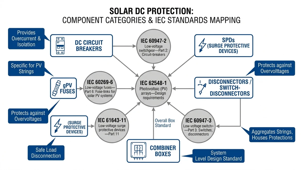
For buyers and engineers, the main component relationships are clear: breakers manage resettable overcurrent interruption, fuses provide fast current-limiting protection, SPDs handle transient overvoltage, and disconnectors support safe isolation.
A 直流遮断器 provides resettable overcurrent and short-circuit protection, with ratings commonly governed by IEC 60947-2 in industrial PV applications. For string-level protection in high-voltage arrays, DC MCBs are often selected in the 6–10 kA breaking-capacity range, depending on fault current calculations.
gPV fuses complement breakers by clearing faults quickly and limiting current under PV-specific duty conditions.
Surge protection devices are used to control transient overvoltage, while DC switch disconnectors provide safe isolation for maintenance and emergency shutdown. In practice, these devices should be selected as part of one coordinated DC protection stack rather than as independent accessories.
For troubleshooting and specification review, the solar PV system failure and DC protection errors guide covers common field misapplications, and the surge protection and SPD selection guide explains Type I and Type II coordination in more detail.
Because higher DC voltage increases arc-interruption difficulty and can raise available fault energy, devices that worked at 1000 VDC may no longer be suitable. The change affects breakers, fuses, SPDs, and insulation coordination together.
No, not every array needs string fusing, but when reverse current from parallel strings can exceed safe limits, gPV fuses are typically the appropriate choice. They are designed specifically for PV fault behavior and coordination.
A DC breaker is resettable and useful for switching plus overcurrent protection, while a gPV fuse is a sacrificial device optimized for fast fault clearing in photovoltaic circuits. Many systems use both at different protection levels.
Bifacial modules can increase effective short-circuit current due to rear-side gain, which pushes required fuse ratings higher than older monofacial assumptions. If sizing is not updated, selectivity problems can appear upstream.
AFCI should be included when code requires it, when insurers demand it, or when the project has elevated fire-risk exposure from connectors, rooftop routing, or long DC runs. It helps detect arc conditions that ordinary overcurrent devices may miss.
They add visibility and faster diagnostics by monitoring each string, reporting faults remotely, and often integrating AFCI and SPD status signals. That makes maintenance more targeted and reduces time spent locating underperforming strings.
Yes. At higher elevations, lower air density reduces insulation performance and cooling, which can lower the effective voltage capability of a device unless derating is considered in advance.