住所
304ノース・カーディナル
セント・ドーチェスター・センター(マサチューセッツ州02124
勤務時間
月曜日~金曜日:午前7時~午後7時
週末午前10時~午後5時
住所
304ノース・カーディナル
セント・ドーチェスター・センター(マサチューセッツ州02124
勤務時間
月曜日~金曜日:午前7時~午後7時
週末午前10時~午後5時

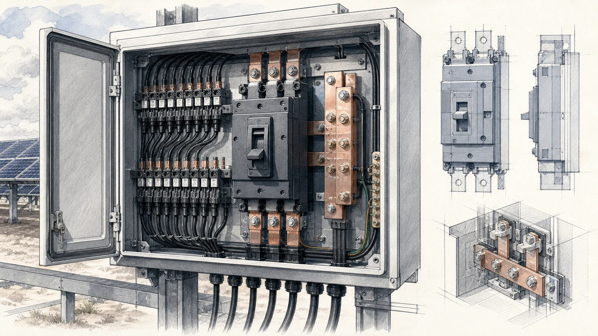
Selecting a DC circuit breaker for a photovoltaic array is not only about matching rated current. The more critical question is whether the breaker can safely interrupt the maximum prospective DC fault current at the actual PV system voltage. In practical terms, dc circuit breaker breaking capacity pv selection means matching fault duty to the breaker’s certified DC interrupting performance.
For PV combiner boxes, inverter inputs, battery-coupled solar systems, and DC distribution panels, Sinobreaker DC Circuit Breakers should be evaluated by voltage rating, pole configuration, short-circuit breaking capacity, and the service expectation after a fault.
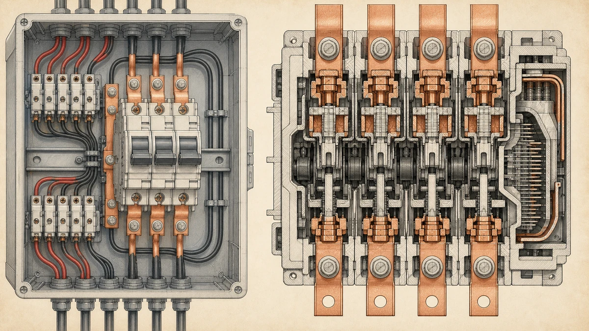
DC faults are harder to interrupt than AC faults because DC has no natural current zero crossing. Once an arc forms inside a switching device, the breaker must force the arc to extinguish through its internal arc chute, contact spacing, magnetic blowout design, and pole arrangement.
In a PV array, the available short-circuit current may look modest compared with large AC switchboards, but the DC voltage can be high and sustained. A breaker that is suitable at one DC voltage may not be suitable at another. This is why a PV DC breaker must be selected using the exact operating conditions, not only the front-label current rating.
IEC 60947-2:2024 applies to circuit-breakers for circuits up to 1,500 V DC and includes requirements relevant to installations handled by skilled persons. For PV systems approaching 1,000 V DC or 1,500 V DC, this standard context is especially important because voltage directly affects arc interruption stress.
イク, or ultimate short-circuit breaking capacity, is the maximum fault current that a circuit breaker can interrupt under specified test conditions. After interrupting at Icu, the breaker may not be suitable for continued normal service without inspection or replacement.
For PV protection, Icu answers the safety-critical question: can this DC circuit breaker interrupt the maximum prospective fault current without catastrophic failure?
Ics, or service short-circuit breaking capacity, indicates the fault current level at which the breaker can interrupt and still remain available for normal service afterward. In other words, Ics is not only about interruption; it is about continued usability.
Where uptime and fast restoration matter, Ics deserves close attention. A breaker with adequate Icu but low Ics may protect against a severe event, but it may not be intended for repeated or continued operation after that level of fault.
Rated current, such as 16 A, 32 A, 63 A, or 125 A, describes the current the breaker can carry under defined conditions. Breaking capacity describes the fault current it can interrupt.
These two values are related to different duties. A PV string breaker may carry normal operating current correctly but still be unsuitable if its DC breaking capacity is lower than the available fault current at the array voltage.
PV fault duty depends on the array architecture, module short-circuit current, number of parallel strings, conductor layout, and available backfeed sources. In many PV arrays, a fault in one string can be fed by the other parallel strings. In hybrid systems, battery or inverter contributions may also need to be considered depending on the topology.
A conservative evaluation should identify the maximum current that could flow through the breaker during a short circuit. The breaker’s DC breaking capacity must then be checked at the relevant DC voltage and pole arrangement.
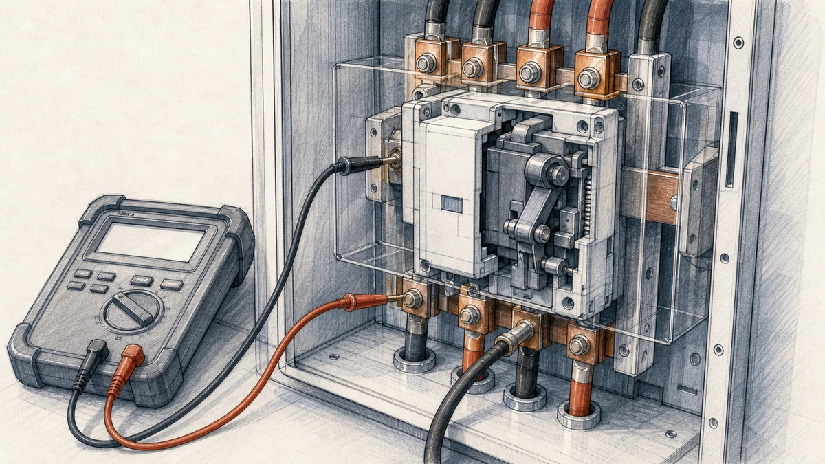
Use the PV module datasheet to find the short-circuit current, usually marked Isc. Apply the required design multipliers from the applicable local code or engineering standard, especially where irradiance and temperature can raise current above standard test conditions.
For a simple array with multiple parallel strings, the prospective current feeding a fault may be based on the contribution from the remaining strings. In a combiner application, this is one reason individual string protection becomes important when several strings are paralleled.
Some PV DC circuits are not supplied only by modules. Energy storage systems, DC buses, charge controllers, and inverter input structures may affect available fault current. A breaker selected only from PV module Isc may be undersized if another source can contribute to the same fault.
When the installation includes batteries or a common DC bus, confirm whether the Sinobreaker DC Circuit Breaker is being used in a PV string circuit, array output circuit, battery circuit, or DC distribution circuit. Each location can have a different fault duty.
A DC breaker’s short-circuit breaking capacity is not universal across all voltages. A breaker that interrupts a specified current at 250 V DC may have a different performance at 500 V DC, 1,000 V DC, or 1,500 V DC.
Always match three values together:
Catalog data for PV DC breakers must be read carefully. The relevant breaking capacity may depend on DC voltage, number of poles connected in series, polarity, and system earthing. Published guidance from major breaker manufacturers emphasizes reading DC breaker data according to the applicable voltage, pole arrangement, earthing configuration, and stated short-circuit breaking capacity.
In DC applications, multiple breaker poles are often connected in series to divide the voltage and improve arc interruption. A two-pole or four-pole arrangement may be required to reach the system voltage rating.
Do not assume that each pole can be used independently at the full marked voltage. Follow the wiring diagram and polarity marking provided for the specific Sinobreaker DC Circuit Breaker model.
In a grounded PV system, one conductor may be referenced to earth. In an ungrounded or functionally grounded system, both positive and negative conductors may float relative to earth. Fault behavior and voltage stress across breaker poles can differ.
This is why the breaker selection should account for the system earthing configuration. A DC circuit breaker suitable for one PV earthing arrangement may require a different pole connection or model selection in another.
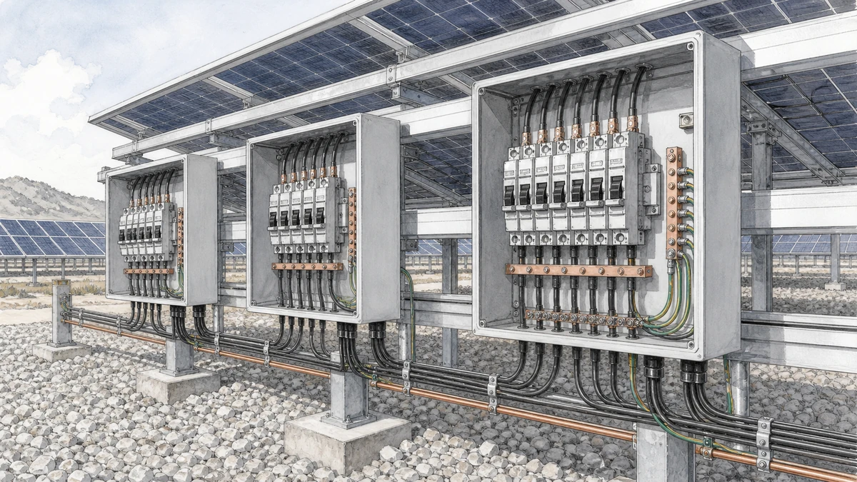
A practical selection workflow helps avoid under-specifying the breaker.
Identify the highest possible PV open-circuit voltage, including low-temperature correction. The selected breaker must be rated for that DC voltage or higher using the required pole arrangement.
For example, a nominal 1,000 V DC PV array should not be checked only against typical operating voltage. It must be evaluated against corrected maximum open-circuit voltage.
Determine the maximum current that can flow through the breaker during a fault. Include parallel PV string contribution and any additional source contribution that applies to the circuit location.
The calculated fault current should be below the breaker’s stated DC breaking capacity at the same voltage and configuration.
Use Icu to verify safe interruption at the maximum fault level. Use Ics to understand whether the breaker is intended to remain serviceable after interrupting that level of short-circuit current.
For critical PV assets, selecting a breaker with an Ics value close to Icu can support better post-fault service continuity, subject to inspection and local maintenance procedures.
Many PV DC breakers are polarity-sensitive. Reverse wiring can reduce arc-control performance or create unsafe interruption conditions.
Before installation, confirm:
The breaker must protect the circuit conductors and coordinate with upstream or downstream protection. Cable ampacity, thermal withstand, isolators, fuses, surge protective devices, and inverter input limits should all be considered.
Breaking capacity is essential, but it is only one part of a complete PV DC protection design.
An AC breaker rating cannot be transferred directly to DC. DC arc interruption requires a different test basis and internal design. Always use the DC voltage and DC breaking capacity data.
A breaker may show different breaking capacities at different DC voltages. Selecting from the highest current value in a table without matching the voltage column can lead to unsafe specification.
Additional poles may be required, but only the manufacturer’s approved series connection determines the actual voltage and breaking performance. Field assumptions are not a substitute for the wiring diagram.
PV breakers must carry normal current and interrupt fault current. A design that checks only continuous current misses the most important safety duty.
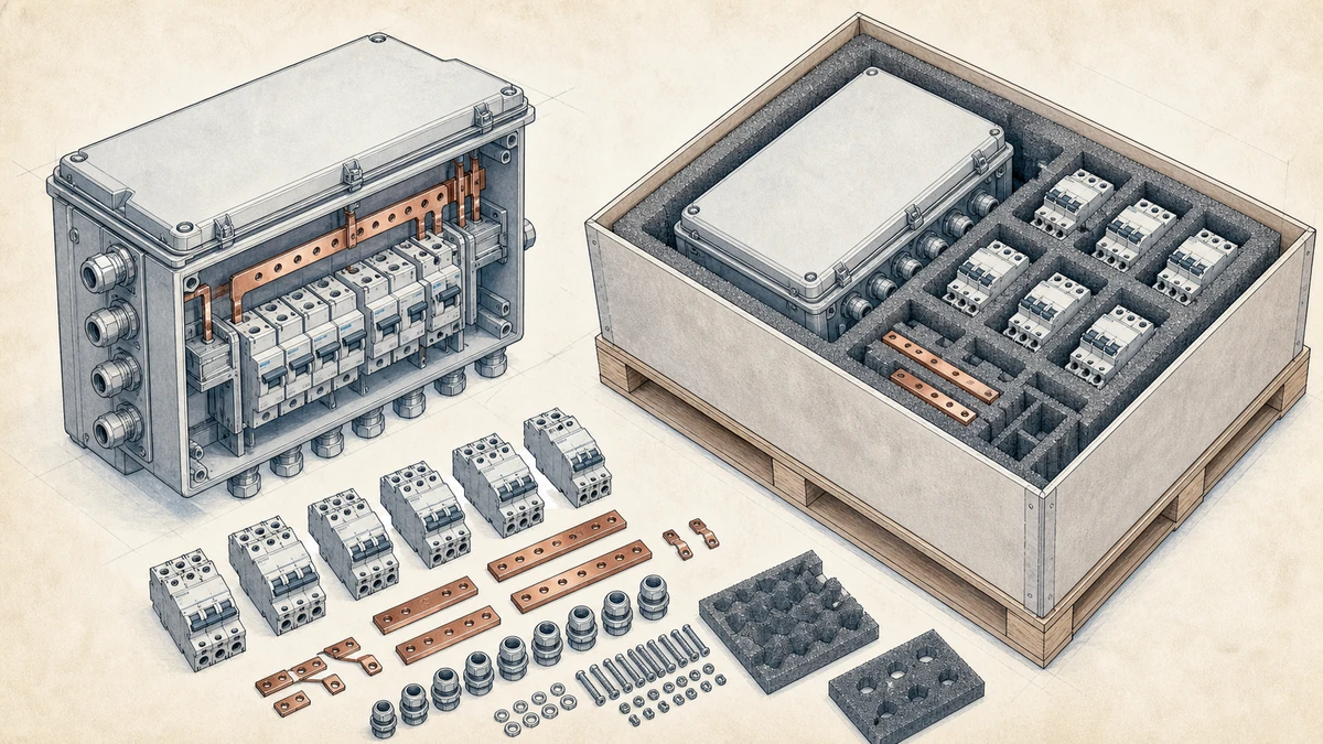
Before finalizing a Sinobreaker DC Circuit Breaker for a PV array, confirm the following:
The breaking capacity should be higher than the maximum prospective short-circuit current at the breaker’s installation point, checked at the actual DC system voltage and required pole configuration. Do not select by rated current alone.
Both matter. Icu confirms the maximum fault current the breaker can interrupt safely. Ics indicates the level at which the breaker can interrupt and remain available for normal service afterward. For critical PV systems, Ics is especially useful when evaluating post-fault continuity.
No. DC breaking capacity depends on voltage, pole arrangement, and system configuration. A breaker suitable for one PV voltage may not be suitable for a higher-voltage array unless its datasheet confirms that rating under the correct wiring conditions.