住所
304ノース・カーディナル
セント・ドーチェスター・センター(マサチューセッツ州02124
勤務時間
月曜日~金曜日:午前7時~午後7時
週末午前10時~午後5時
住所
304ノース・カーディナル
セント・ドーチェスター・センター(マサチューセッツ州02124
勤務時間
月曜日~金曜日:午前7時~午後7時
週末午前10時~午後5時

DC circuit breaker failures account for a disproportionate share of unplanned downtime in solar PV, battery storage, and EV charging systems. Under IEC 60947-2, which governs low-voltage DC circuit breakers up to 1500 VDC, improper selection and installation are among the leading causes of premature tripping and arc-fault incidents. In a 35 MW ground-mount PV installation in Hebei Province in 2023, technicians traced repeated nuisance trips to five avoidable specification errors that should have been caught during commissioning.
This article covers the 10 most common 直流遮断器 mistakes engineers make, along with practical ways to identify, troubleshoot, and correct them before they become costly failures.

The reason these errors become expensive so quickly is rooted in how DC faults behave once an arc forms.
In AC systems, current crosses zero naturally every half cycle, giving the arc a built-in opportunity to extinguish. In DC systems, current is continuous, so a DC circuit breaker must mechanically stretch, cool, and split the arc while generating enough counter-voltage to force current to zero. At 1000-1500 VDC, arc chute assemblies often must build arc voltage 20-30% above system voltage, which is a fundamentally different interruption task from AC protection.
IEC 60947-2 sets the breaking-capacity requirements for DC molded case circuit breakers, including verified interruption at rated voltage under prospective fault currents that may reach 10-25 kA in PV and battery applications.
A 30 MW ground-mount PV installation in Gansu Province in 2023 documented arc-fault events where string breakers rated for 600 VDC had been installed on 1000 VDC strings. Those devices failed to interrupt fault current within 500 ms, leading to conductor insulation damage across three combiner boxes. Properly rated DC MCB cleared comparable faults in under 15 ms.
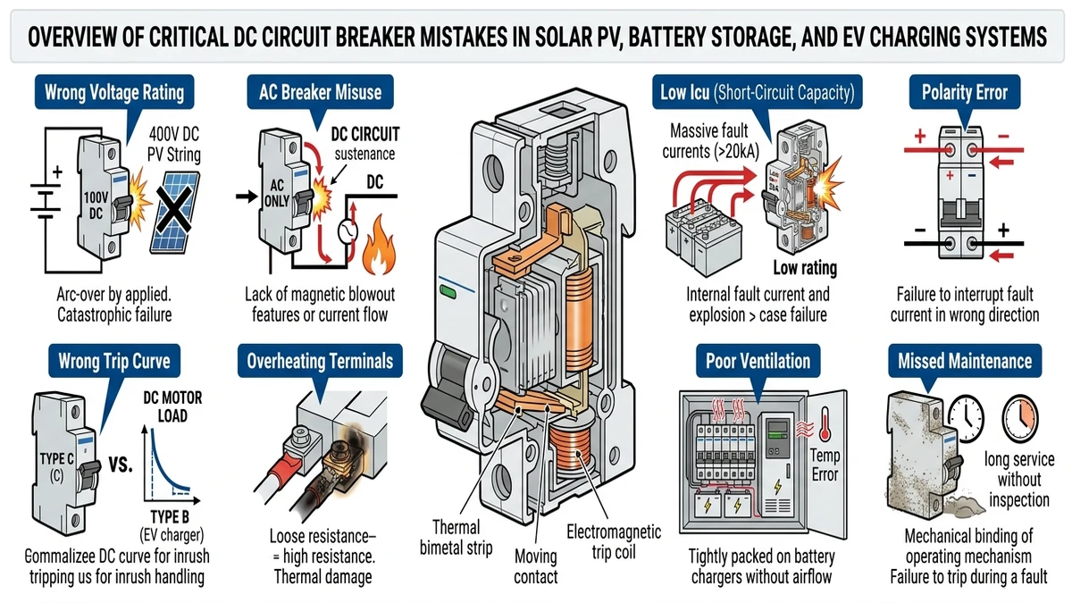
In AC systems, a misapplied breaker often causes nuisance tripping. In DC systems, the same kind of mistake can produce sustained arcing, thermal runaway, or fire, especially inside enclosed DC distribution boxes where heat cannot dissipate easily.
Most field failures can be traced back to a short list of repeated specification, installation, or maintenance decisions.
Error: Installing standard AC MCBs on DC strings.
Failure mode: AC breakers lack the magnetic arc blowout mechanisms needed for DC interruption. Without a natural current zero crossing, the arc can persist, leading to contact welding or enclosure fire.
Code reference: IEC 60898-2 governs DC MCBs specifically; AC-rated IEC 60898-1 devices are not compliant for DC use.
Fix: Replace them with a DC-rated MCB tested to IEC 60898-2 at the system’s rated DC voltage.
Error: Selecting a breaker with Icu below the prospective short-circuit current at the installation point.
Failure mode: The breaker cannot interrupt the available fault current, resulting in sustained arcing, busbar damage, or device rupture.
Code reference: IEC 60947-2 requires Icu and Ics ratings to be verified against calculated fault levels.
Fix: Calculate prospective short-circuit current at each protection point. In a typical 1500 VDC architecture, busbar fault current can reach 20-40 kA, so breaker selection must match that level.
Error: Installing unidirectional DC breakers in ESS or EV charging applications where current can reverse.
Failure mode: Arc interruption fails during reverse current flow because the breaker is not rated to extinguish the arc in that direction.
Fix: Specify breakers rated for bidirectional breaking. For battery storage systems, see the DC circuit breaker ESS protection guide for selection criteria.
Error: Using B-curve breakers on solar string circuits.
Failure mode: Nuisance tripping during morning irradiance ramp-up, when inrush can temporarily reach 1.25× Isc.
Code reference: IEC 62548-1 defines string protection requirements; C- or K-curve devices are generally more suitable for PV strings.
Fix: Use C-curve devices or gPVヒューズ designed for photovoltaic protection under IEC 60269-6.
Error: Applying breakers at full rated current in enclosures where ambient temperature exceeds 40°C.
Failure mode: Thermal-magnetic trip elements either trip too early or shift calibration enough to miss real overload conditions.
Code reference: IEC 60947-2 Annex B defines temperature derating behavior; many devices require roughly 1-2% current derating per °C above 40°C.
Fix: Use manufacturer derating tables. In rooftop installations where enclosure temperatures reach 55-65°C, effective current capacity may drop by 15-25%.
Error: Using a single-pole breaker to interrupt both conductors in an ungrounded DC system.
Failure mode: One conductor remains energized, creating a shock hazard and defeating isolation.
Code reference: IEC 60364-7-712 requires both poles to be switched in ungrounded PV DC systems.
Fix: Use 2-pole DC breakers or a 直流開閉器 rated for simultaneous double-pole interruption.
Error: Installing DC breakers without coordinated upstream or downstream SPD protection.
Failure mode: Lightning-induced transients exceed the breaker’s impulse withstand voltage, causing insulation stress, hidden damage, or nuisance tripping.
Code reference: IEC 61643-31 governs SPD selection for PV DC circuits; SPD Up should remain below equipment Uimp.
Fix: Coordinate SPD protection level with breaker impulse withstand rating. A surge protection device with Up ≤ 2.5 kV is commonly required for 1000 VDC string circuits.
Error: Under-torquing terminal screws during installation or failing to re-torque after thermal cycling.
Failure mode: Increased contact resistance creates localized heating. At 30-50 A string current, even a few milliohms of added resistance can accelerate insulation breakdown and trigger thermal runaway.
Code reference: Manufacturer torque specifications apply under IEC 60999-1 for connecting devices used with copper conductors.
Fix: Use a calibrated torque screwdriver, then re-torque after the first 100 operating hours and during annual maintenance.
Error: Pulling breakers from AC panel inventory for use in DC combiner boxes or DC distribution assemblies.
Failure mode: AC devices are not type-tested for DC arc interruption; arc chute geometry, contact gap, and magnetic blowout design are optimized for AC behavior.
Code reference: UL 489B and IEC 60947-2 both require DC-specific type testing.
Fix: Keep separate DC-rated inventory and use components intended for DC distribution environments.
Error: Treating DC breakers as maintenance-free devices.
Failure mode: Contact oxidation, spring fatigue, and arc chute contamination accumulate silently. A breaker that has not operated in years may fail exactly when overload protection is needed.
Code reference: IEC 60947-2 recommends periodic mechanical operation verification; NFPA 70B advises functional testing intervals based on environment and duty.
Fix: Schedule annual manual trip tests, log trip times, and investigate any deviation greater than 20% from commissioning baseline.

[Expert Insight]
– If a DC breaker body shows browning near terminals, check torque first before assuming overload.
– In retrofit work, verify polarity marks physically on the device, not just on the panel drawing.
– When replacing a failed unit, compare fault level at that point with installed Icu before fitting the same model again.
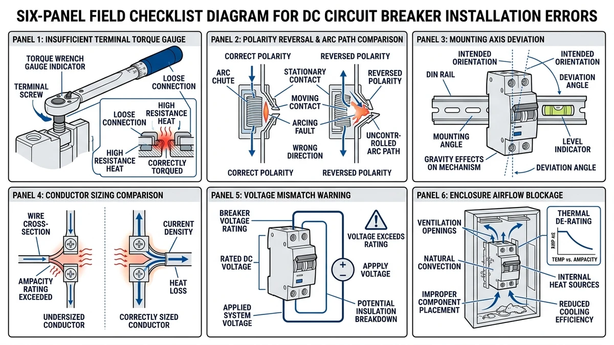
Even a correctly specified breaker can underperform if field installation conditions compromise its interrupting behavior.
Under-torquing below the specified value, often 2.5-4 N·m for M6 terminals, raises contact resistance and creates localized heating that slowly degrades the thermoplastic housing around the arc chute. Over-torquing can crush conductor strands, reduce effective cross-section, and increase I²R losses at the connection.
DC breakers often use asymmetric magnetic blowout geometry. Reversing line and load terminals changes the intended arc path and can drive the arc away from the chute plates instead of into them.
Gravity-assisted arc chute designs depend on correct mounting orientation. If the breaker is installed horizontally or inverted, arc elongation becomes less reliable and re-strike risk increases after interruption.
DC current is continuous, so conductor heating remains steady rather than cycling through AC zero crossings. Conductors sized too tightly run hotter at the terminal entry point, which accelerates insulation aging close to the breaker body.
A common field shortcut is installing a 1000 VDC breaker in a 1500 VDC architecture. That removes the voltage margin needed for arc extinction. Refer to DC MCB selection guidance when matching breaker voltage class to string design.
Arc chute cooling depends on airflow. Over-packed or poorly ventilated DC distribution boxes can trap heat and push internal ambient temperature 15-25°C above rated conditions, compressing the thermal trip curve and shortening service life.
For battery storage installations where bidirectional fault current is possible, the DC circuit breaker ESS protection guide covers additional orientation and rating considerations.
Once single-device mistakes spread across a protection chain, coordination failures can turn a localized fault into a wide-area outage.
Protective coordination means the breaker nearest the fault should trip first while upstream devices remain closed. In DC systems, this is harder to achieve because fault current can rise rapidly and does not self-extinguish. Without coordination, a string-level fault may trip the combiner breaker or even the main DC disconnect, taking multiple strings offline.
In a 60 MW ground-mount PV installation in Hebei Province in 2023, maintenance logs showed that 70% of unplanned outages affected eight or more strings at once. Root cause analysis linked the problem to mismatched time-current curves between string-level DC MCBs and combiner-level DC MCCB, with the upstream device tripping faster than the downstream unit during moderate overcurrent events.
A useful starting point for DC coordination is to size the upstream breaker’s rated current at least 1.6× above the downstream breaker’s rated current, while ensuring the upstream trip threshold at the relevant fault level is at least 20% slower.
For systems above 1000 VDC, this margin often needs to be wider. In utility-scale plants, prospective short-circuit current at a 1500 VDC busbar commonly reaches 15-25 kA, and at those levels even modest mismatches in Icu or trip behavior can collapse selectivity.
Proper coordination also depends on using devices from the same voltage class throughout the protection chain. Mixing a 600 V-rated breaker into a 1000 V string circuit, even during temporary maintenance, is one of the most common system-level errors seen in DC circuit breaker field audits. In ESS applications, bidirectional fault current adds another coordination layer, which is addressed in the DC circuit breaker ESS protection guide.
[Expert Insight]
– Plot actual manufacturer time-current curves instead of relying only on rated current ratios.
– Recheck selectivity whenever string counts, inverter inputs, or battery modules are added during expansion.
– Temporary maintenance substitutions are a frequent source of lost coordination; treat them like permanent design changes.
Before ordering or commissioning equipment, a structured review of the key parameters catches most of the mistakes that later appear as field failures.
| # | パラメータ | What to Verify | Common Error |
|---|---|---|---|
| 1 | Rated Voltage (VDC) | Breaker Vrated ≥ maximum open-circuit string voltage including temperature correction | Using AC-rated breaker or underrating by ignoring cold-weather Voc spike |
| 2 | Breaking Capacity (Icu) | Icu ≥ prospective short-circuit current at installation point; verify per IEC 60947-2 | Selecting Icu based on nominal current, not fault current |
| 3 | 連続定格電流 | In ≥ 1.25 × Isc for PV strings per IEC 62548-1 | Sizing only to Isc and ignoring margin |
| 4 | Polarity Configuration | Confirm unipolar vs. bipolar interruption matches circuit topology | Installing a unidirectional breaker where current can reverse |
| 5 | Number of Poles | Match pole count to system grounding scheme | Using 1P protection where both poles must be interrupted |
| 6 | Trip Curve Type | Select B, C, or D curve to match load inrush | Choosing an unsuitable curve and creating nuisance trips or missed faults |
| 7 | Operating Temperature Range | Derate current per manufacturer table if ambient exceeds 40°C | Ignoring rooftop or enclosure heat |
| 8 | Certification Standard | IEC 60898-2 for MCBs, IEC 60947-2 for MCCBs, or UL 489B where required | Applying an AC-only certified breaker to DC service |
| 9 | Surge Coordination | Verify upstream surge protection device Up is below breaker impulse withstand rating | Leaving transient protection uncoordinated |
| 10 | Application-Specific Rating | Confirm PV, ESS, or EV charging suitability | Using a standard PV breaker where bidirectional duty is required |
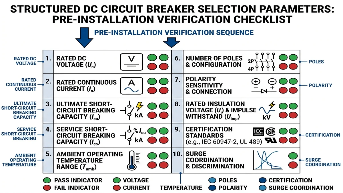
For DC MCB selection specifically, continuous current rating, trip curve, and temperature derating are among the most frequently missed checks in field audits.
Making sure the product you specify matches the full operating environment, not just the headline ratings, is what prevents most of these failures.
Every mistake in this article ultimately comes from evaluating a breaker against one or two parameters while ignoring the rest. Voltage rating, breaking capacity, current rating, polarity, mounting orientation, operating temperature, short-circuit current, trip curve, certification, and application type all interact.
Sinobreaker’s DC circuit breaker range is built around that full-parameter approach. The DC MCB series covers systems from 12 VDC to 1500 VDC with breaking capacities up to 10 kA, IEC 60898-2 certification, and multiple trip-curve options for resistive and capacitive load profiles. The DC MCCB series extends coverage to 1500 VDC with up to 50 kA Icu for combiner boxes and battery storage bus protection where available fault current is much higher.
If the application is energy storage or EV charging, use the ESS and battery storage protection guide and the EV charging station breaker guide to confirm bidirectional duty, fault current, and coordination requirements. If a product cannot be verified against all 10 parameters before installation, it is not ready to specify. For broader low-voltage protection context, IEC standards and conformity resources can also be reviewed through the IEC official website.
No. AC breakers are built around interruption behavior that depends on current zero crossings, while DC circuits require dedicated arc control for safe interruption.
The most common causes are incorrect trip curve selection, ambient temperature derating that was never applied, or heat caused by loose terminations.
A yearly functional check is a practical baseline for most installations, with shorter intervals in dusty, hot, or high-duty environments.
The device may fail to extinguish the arc during a fault, which can lead to contact welding, insulation damage, or fire.
In ungrounded DC systems, yes. Opening only one conductor can leave the circuit partially energized and unsafe to service.
Compare the breaker’s Icu with the calculated prospective fault current at the exact installation point, not just the circuit’s normal operating current.


