住所
304ノース・カーディナル
セント・ドーチェスター・センター(マサチューセッツ州02124
勤務時間
月曜日~金曜日:午前7時~午後7時
週末午前10時~午後5時
住所
304ノース・カーディナル
セント・ドーチェスター・センター(マサチューセッツ州02124
勤務時間
月曜日~金曜日:午前7時~午後7時
週末午前10時~午後5時


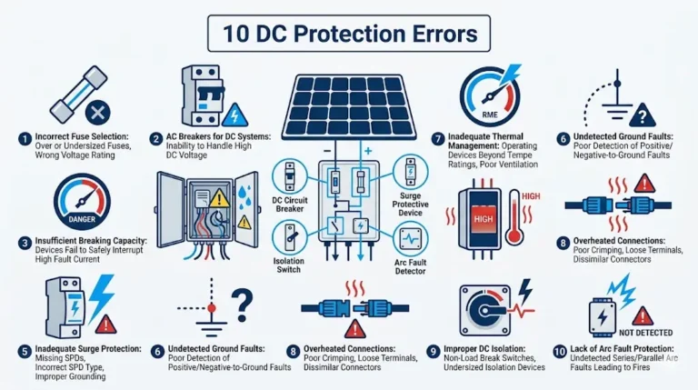
PV protection technology extends far beyond basic overcurrent devices and surge protectors—modern photovoltaic systems require sophisticated fault detection and isolation capabilities that identify, classify, and respond to multiple simultaneous fault conditions without unnecessary system shutdowns.
Traditional electrical protection assumes predictable fault characteristics: short circuits create high currents that trip breakers, ground faults activate residual current devices, overvoltages trigger surge protectors. Solar DC systems complicate this model with sustained arc faults that don’t increase current, ground faults that may not trip standard protection, parallel source configurations that distribute fault current unpredictably, and high-voltage DC that makes arc extinction challenging.
This guide examines modern protection technologies specifically engineered for photovoltaic applications. You’ll learn how arc fault circuit interrupters detect dangerous arcs using multi-parameter analysis, how ground fault detection isolates faults in ungrounded systems without shutting down production, how rapid shutdown systems integrate with protection for enhanced safety, and how intelligent protection coordination prevents nuisance trips while maintaining comprehensive fault coverage.
💡 重要な洞察: Effective PV protection isn’t about detecting faults faster or with higher sensitivity—it’s about distinguishing real hazards from normal operating transients, coordinating multiple protection devices to isolate minimum affected area, and maintaining system availability while ensuring safety. A protection system that trips unnecessarily is as problematic as one that fails to trip when needed.
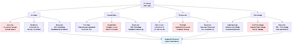
Solar DC systems exhibit fault behaviors fundamentally different from AC electrical systems, requiring specialized protection approaches.
DC arcs sustain indefinitely without zero-crossing current interruption, creating thermal hazards that standard overcurrent protection cannot detect.
Arc Fault Physics:
AC arcs self-extinguish 120 times per second as current crosses zero, limiting thermal buildup. DC arcs have no zero crossing—once established, they persist until physically interrupted or current source removed.
Arc initiation mechanisms in PV:
– Loose connections creating intermittent contact
– Insulation degradation from UV exposure or physical damage
– Connector corrosion increasing contact resistance
– Cable damage from rodents or installation errors
– Water infiltration into junction boxes
Detection challenge: Series arc faults don’t increase circuit current—a 5A string with series arc still measures 5A. The current passes through the arc rather than bypassing it, making traditional overcurrent protection ineffective.
Parallel arc characteristics: Fault current limited by panel short-circuit current (typically 8-12A per string), insufficient to trip standard circuit breakers rated 15-20A. A parallel fault drawing 10A from 600V source creates 6,000W thermal hazard invisible to overcurrent protection.
Why DC arcs are more dangerous:
Energy in arc = V × I × t
For comparable current, DC arc energy is 5-10× higher than AC due to:
– No zero-crossing interruption (continuous energy transfer)
– Higher system voltage (600-1500V vs 120-240V AC)
– Ionized plasma channel maintains lower resistance
Real consequence: Series DC arc at 400V, 5A generates 2,000W continuous heat in confined junction box or conduit, igniting surrounding materials within 1-3 minutes. Standard protection detects nothing abnormal—current and voltage remain within normal ranges.
Most modern PV systems use ungrounded (floating) DC circuits per NEC 690.35, where ground faults don’t create obvious overcurrent conditions.
Grounded vs. Ungrounded System Behavior:
Grounded system (single ground fault):
– Fault current flows positive → ground → negative through path of least resistance
– Magnitude limited by fault resistance and system impedance
– Easy detection via residual current monitoring (sum of currents ≠ 0)
– First fault trips protection immediately
Ungrounded system (first ground fault):
– No complete current path established (floating system now grounded at fault point)
– System continues operation normally
– Fault resistance becomes new ground reference
– Detection requires impedance measurement, not current measurement
- System remains energized and operational
Second ground fault creates hazard:
After first fault grounds one conductor, second fault on opposite polarity creates complete circuit through ground, potentially causing:
– High fault current through unintended paths
– Shock hazard from metallic enclosures
– Fire ignition from resistive heating
– No tripping if current below breaker rating
Detection technology requirement: Ground fault detection for ungrounded systems must measure impedance-to-ground continuously, detecting resistance changes that indicate developing faults, not waiting for fault current to flow.
PV overcurrent faults differ from traditional electrical faults due to current-limited source characteristics.
Short-Circuit Current Limitation:
Solar panels are current sources, not voltage sources. Maximum fault current = Isc (short-circuit current), typically 1.1-1.3× rated Imax.
Contrast with transformer-fed AC systems:
– AC fault current: 10-100× normal current (thousands of amperes)
– DC PV fault current: 1.3× normal current (single-digit to low double-digit amperes)
Protection implications:
Standard molded case circuit breakers rely on high fault current to trip magnetic element quickly. PV fault currents may not reach magnetic trip threshold, causing:
– Slow thermal trip (minutes instead of milliseconds)
– Sustained high current causing conductor heating
– Insufficient let-through current to clear upstream protection
計算例:
10-panel string, each panel Isc = 9.5A
Maximum string fault current = 9.5A (not 10× or 20× normal)
15A breaker magnetic trip threshold = 150A (10× rating)
String fault current insufficient to trip magnetic element
Solution: PV-rated circuit protection devices with lower magnetic trip thresholds (3-5× rating) or electronic trip units detecting smaller overcurrent increases characteristic of solar faults.
AFCI devices detect dangerous arcs using sophisticated signal processing that distinguishes hazardous conditions from normal switching transients.
Modern AFCI technology analyzes multiple electrical signatures simultaneously to avoid false trips while detecting real arc faults.
Detection Parameter 1: Broadband Noise Signature
Arcs generate electromagnetic interference across wide frequency spectrum (100kHz – 10MHz) as plasma channel forms and collapses thousands of times per second.
Signal processing:
– High-frequency current transformer samples circuit current at 1-10 MHz
– FFT (Fast Fourier Transform) analysis identifies noise spectrum
– Compare measured spectrum to arc fault signature database
– Threshold detection: If broadband noise exceeds 40-60 dB above baseline, increment fault counter
Normal vs. Arc Spectrum:
– Normal operation: <10 db noise above 1 mhz
- switching transients: 20-30 spike, <1ms duration
- arc fault: 40-80 continuous, multiple frequenciesDetection Parameter 2: Current Pulse Characteristics
Arcs create distinct current waveform irregularities as arc resistance varies with plasma temperature and ionization level.
Pulse detection criteria:
– Pulse width: 5-50 μs (characteristic of arc reignition)
– Pulse amplitude: >5% current deviation from steady-state
– Pulse frequency: 50-500 Hz (too slow for EMI, too fast for switching)
– Pulse pattern: Semi-random intervals (not periodic like PWM)
Algorithm:
Detect pulses meeting above criteria → Count pulses in 0.5-second window → If count >30 pulses and duration >0.5s, initiate trip sequence.
Detection Parameter 3: dI/dt Analysis
Arc ignition and extinction create rapid current changes distinct from normal operation or switching events.
Rate-of-change thresholds:
– Normal operation: dI/dt < 50 A/ms
- Inverter switching: dI/dt = 100-500 A/ms (regular pattern)
- Arc fault: dI/dt = 200-2000 A/ms (irregular pattern)
Combined with frequency analysis, distinguishes arc faults from high-speed switching in power electronics.
Detection Parameter 4: Load Signature Recognition
AFCI learns normal load signatures during initial operation, comparing ongoing behavior to baseline patterns.
Machine learning approach:
– Capture current/voltage waveforms during first 100 hours operation
– Build statistical model of normal transients (inverter startup, cloud transitions, etc.)
– Compare real-time waveforms to learned baseline
– Flag deviations exceeding statistical confidence threshold (typically 3σ)
This adaptive approach reduces false trips from legitimate system behavior while detecting abnormal patterns characteristic of developing faults.
UL 1699B – DC Arc Fault Circuit Protection:
Standard specifically for PV systems, requiring:
– Detection of series and parallel arc faults in <0.5 seconds
- Immunity to 50+ types of nuisance trip sources (switching transients, load changes, etc.)
- Operational testing every 6 months via integrated test button
- Indication of fault condition (audible alarm or visual indicator)
- Maximum 5% false trip rate under test conditions
NEC 690.11 Arc Fault Protection:
Requires AFCI for PV systems with DC source circuits operating above 80V, with exceptions:
– Arrays installed in metal conduit from modules to first disconnect
– Systems with PV modules containing integrated arc fault protection
– Ground or pole-mounted systems with no exposed wiring in buildings
Installation Requirements:
AFCIs must install:
– One per maximum of 2 strings (or per combiner circuit)
– Before first combining point (individual string protection preferred)
– Accessible for manual testing and indicator verification
– In location protected from weather (inside combiner box or building)
Legitimate PV system events can mimic arc fault signatures, requiring intelligent discrimination.
Common False Trip Sources:
Inverter startup transients:
– High inrush current as DC link capacitors charge
– PWM switching commences with complex harmonic content
– Solution: AFCI includes 2-5 second startup delay after voltage detection
Cloud-edge transitions:
– Rapid irradiance changes cause fast current ramps (dI/dt)
– Can occur 10-20 times per day
– Solution: Combine dI/dt with frequency analysis—clouds create low-frequency changes (<10 hz), arcs create high-frequency noise (>1 kHz)
EMI from nearby equipment:
– Variable frequency drives, switched-mode power supplies generate broadband noise
– Can couple into PV wiring via inductive/capacitive paths
– Solution: AFCI includes baseline noise measurement during installation, setting detection threshold above ambient EMI
Module-level power electronics (MLPE):
– Optimizers and microinverters create high-frequency switching (20-100 kHz)
– Can resemble arc fault broadband signature
– Solution: UL 1699B includes specific MLPE immunity testing; modern AFCI recognize MLPE switching patterns
🎯 プロからのアドバイス: During AFCI commissioning, activate test button to verify proper operation, then monitor system for 48 hours to detect any false trips from legitimate operation. If nuisance trips occur, consult manufacturer for sensitivity adjustment or firmware update—do not disable AFCI protection to eliminate trips.
Ground fault detection in ungrounded PV systems uses impedance monitoring rather than residual current measurement, enabling fault detection without creating complete ground circuit.
Method 1: Injection-Based Ground Fault Detection
Periodically injects low-frequency AC signal (typically 1-10 Hz) between DC system and ground, measuring resulting current to calculate impedance.
Operating principle:
Z_ground = V_inject / I_measured
どこでだ:
– V_inject = known AC voltage (typically 10-50V peak)
– I_measured = resulting AC current flow to ground
– Z_ground = impedance to ground (should be >1 MΩ for unfaulted system)
Detection sequence:
1. Inject 10V AC signal at 2 Hz between positive conductor and ground
2. Measure resulting current (expect <10 μa for>1 MΩ system)
3. Calculate impedance: Z = 10V / measured current
4. If Z < 100 kΩ (adjustable threshold), ground fault indicated
5. Repeat measurement on negative conductor
6. Display fault location (positive ground, negative ground, or both)メリット
– Detects first ground fault before second fault creates hazard
– Non-invasive (signal injection doesn’t affect normal operation)
– Can locate fault to positive or negative conductor
– Continuous monitoring (every 10-60 seconds)
制限:
– Cannot pinpoint physical fault location within circuit
– May not detect intermittent faults between injection cycles
– AC injection can couple into sensitive monitoring equipment
Method 2: Differential Voltage Measurement
Measures voltage from each DC conductor to ground continuously, comparing to expected floating values.
Operating principle:
Unfaulted floating system: V_positive-to-ground = V_negative-to-ground (approximately)
Ground fault: Faulted conductor approaches 0V-to-ground, opposite conductor approaches full Voc-to-ground
Detection criteria:
ΔV = |V+ to ground| – |V- to ground|
If ΔV > 50% of Voc, ground fault detected on conductor closer to ground potential.
Implementation:
– High-impedance voltage dividers (>10 MΩ) from each DC conductor to ground reference
– Differential amplifier comparing voltages
– Microcontroller analyzing voltage difference
– Trip signal if imbalance exceeds threshold for >2 seconds
メリット
– Continuous real-time monitoring (no injection required)
– Simple circuitry with high reliability
– Fast detection (<1 second)
- no interference with system operation制限:
– Cannot distinguish between single ground fault and balanced dual ground faults
– Sensitive to capacitive coupling in long cable runs
– May require periodic calibration for drift compensation
Method 3: Residual Current Monitoring (RCM) with Compensation
Measures sum of currents in all DC conductors, detecting leakage current to ground that indicates fault.
Standard RCM: I_leakage = I_positive + I_negative (sum should equal zero)
PV complication: Capacitive coupling and insulation leakage create normal non-zero residual current (10-100 mA typical).
Solution – Compensated RCM:
– Measure baseline leakage during normal operation
– Store baseline in non-volatile memory
– Compare real-time measurement to baseline
– Alert if increase >50 mA indicates developing ground fault
Leakage current components:
I_total = I_fault + I_capacitive + I_insulation
– I_fault = actual ground fault current (hazard)
– I_capacitive = displacement current from cable capacitance (normal, weather-dependent)
– I_insulation = conduction through panel insulation (normal, degrades with age)
Challenge: Distinguishing fault current increase from normal leakage variation requires sophisticated baseline modeling accounting for temperature, humidity, and aging effects.
When ground fault detected, appropriate response depends on fault magnitude and system configuration.
Low-Impedance Fault (<10 kΩ):
Immediate actions:
– Open DC disconnect contactors (interrupt fault current)
– Display alarm condition on inverter/monitoring system
– Log fault event with timestamp and impedance measurement
– Activate visual/audible alarm (required for occupied structures)
– Prevent automatic restart until fault cleared and system reset
Shutdown prevents second fault from creating shock hazard or fire ignition.
Medium-Impedance Fault (10-100 kΩ):
Monitored operation:
– Continue operation with enhanced monitoring (measurement every 10 seconds vs. normal 60 seconds)
– Display warning indication (amber vs. red for high-severity)
– Log impedance trend data for maintenance scheduling
– Alert system owner/operator of developing fault
– Initiate shutdown if impedance decreases below 10 kΩ threshold
Allows continued production while scheduling maintenance during normal downtime.
High-Impedance Fault (>100 kΩ):
Advisory status:
– Log detection event for maintenance review
– Display informational message (not alarm)
– Continue normal operation and monitoring
– May indicate insulation degradation not yet hazardous
– Useful for predictive maintenance scheduling
Prevents unnecessary shutdowns while providing early warning of developing issues.
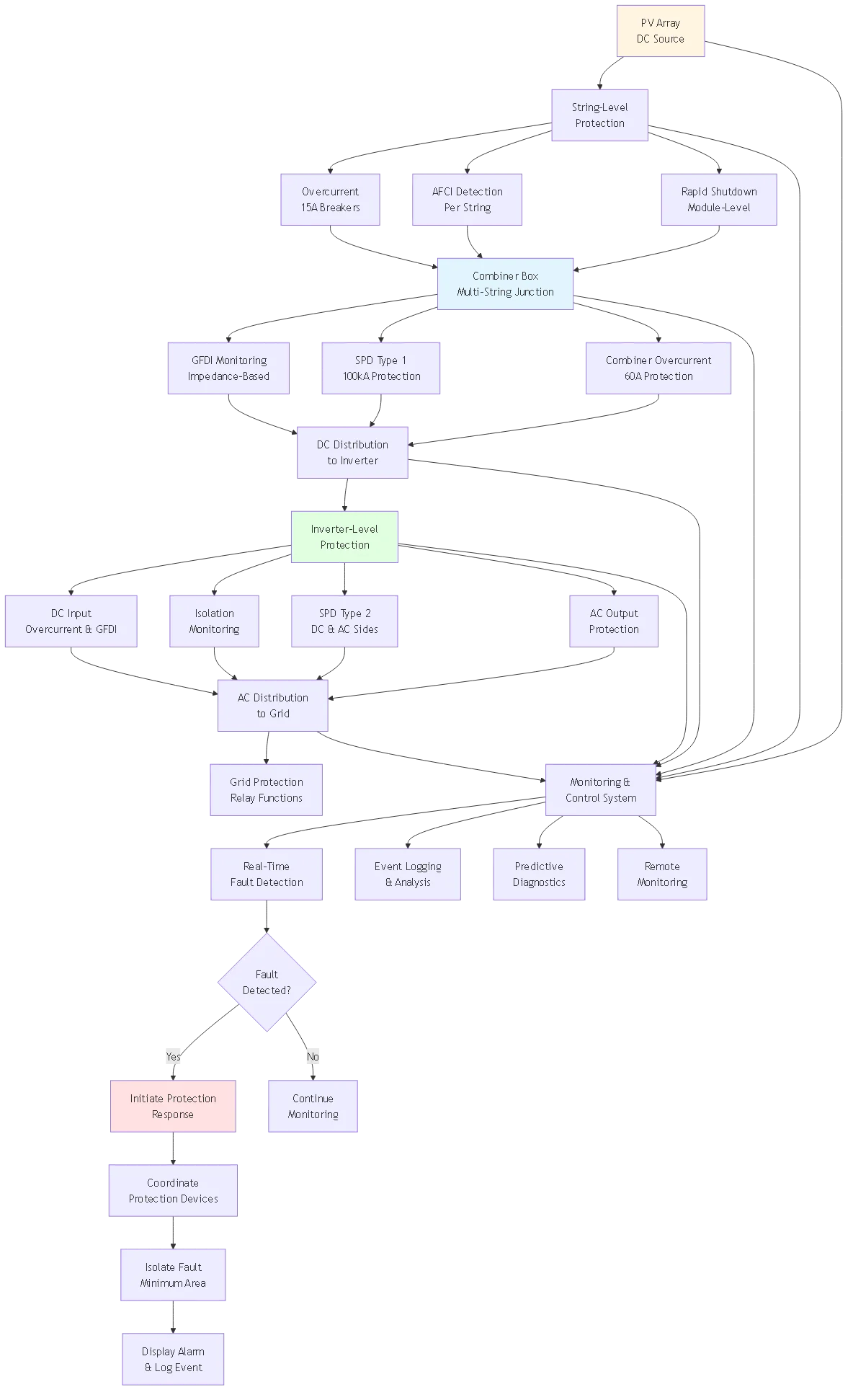
NEC 690.12 rapid shutdown requirements integrate with protection technology, creating coordinated safety systems.
Three-Level Protection Hierarchy:
Level 1 – Array-Level Shutdown:
Reduces voltage at array boundary to <30v within 30 seconds of initiationImplementation:
– Module-level power electronics (MLPE) shut down individual panels
– String-level shutdown devices (solid-state switches) open circuits
– Central array disconnect contactors open at combiner boxes
Level 2 – Controlled Conductor Shutdown:
Reduces voltage more than 1 foot from array to <80v within 30 secondsImplementation:
– Intermediate isolation points in DC wiring runs
– Sectional shutdown capability for large arrays
– Maintains high voltage only in confined, controlled areas
Level 3 – Equipment Shutdown:
Opens all disconnects and interrupts inverter operation
Implementation:
– Inverter ceases power conversion
– DC disconnect opens
– AC disconnect opens
– System fully de-energized
Rapid shutdown systems coordinate with fault detection to enhance safety.
Arc Fault + Rapid Shutdown:
When AFCI detects fault:
1. Immediately initiate rapid shutdown sequence (don’t wait for manual activation)
2. Open array-level controls within 1 second (faster than 30-second code requirement)
3. Display fault indication and location if available
4. Prevent restart until arc fault cleared and AFCI manually reset
Advantage: Rapid voltage reduction extinguishes arc by removing energy source, converting fire hazard to isolated fault suitable for repair.
Ground Fault + Rapid Shutdown:
When GFDI detects low-impedance fault (<10 kΩ): 1. Open DC disconnect (remove fault current source) 2. Initiate array-level shutdown (reduce touch voltage) 3. Maintain shutdown until fault located and repaired 4. Require manual inspection and reset before re-energization
Advantage: Rapid shutdown converts ground fault from potential shock hazard (if second fault develops) to safe isolated condition.
Combined Fault Scenarios:
Protection system must handle simultaneous faults (e.g., arc fault occurring during ground fault condition):
Priority hierarchy:
1. Arc fault = highest priority (fire hazard)
2. Ground fault = second priority (shock hazard)
3. Overcurrent = third priority (equipment damage)
4. Overvoltage = fourth priority (transient stress)
Implementation: Multi-input logic controller prioritizes most severe detected fault, executing appropriate shutdown sequence while displaying all detected conditions for diagnosis.
Manual initiation methods:
– Red emergency stop button at accessible location
– Remote shutdown switch (required in some jurisdictions)
– Firefighter switch (building entry point)
Automatic initiation triggers:
– AFCI detection of arc fault
– GFDI detection of low-impedance ground fault
– Overcurrent protection trip
– Inverter fault shutdown
– Loss of utility grid (anti-islanding)
Coordination requirement: Any automatic shutdown must achieve same voltage reduction as manual shutdown within same time limits (30 seconds array-level, instantaneous for controlled conductors).
Proper coordination ensures faults isolate at appropriate protection level without cascading shutdowns.
Protection devices must coordinate to isolate minimum affected area while clearing faults safely.
Coordination Principles:
Upstream/Downstream Relationship:
- Downstream protection (string level): Fastest response, smallest isolation zone
- Mid-level protection (combiner level): Medium response, sub-array isolation
- Upstream protection (main disconnect): Slowest response, whole-system isolation
Time-Current Coordination:
Each protection level operates in distinct time-current window:
String breakers (10-20A):
– Trip time at 2× rating: 20-60 seconds
– Trip time at 5× rating: 0.5-2 seconds
– Protects individual string, opens before combiner protection
Combiner overcurrent (30-60A):
– Trip time at 2× rating: 60-180 seconds
– Trip time at 5× rating: 2-10 seconds
– Protects combined strings, allows string breakers time to clear fault
Main disconnect (100-400A):
– Trip time at 2× rating: 180-600 seconds
– Trip time at 5× rating: 10-30 seconds
– Last-resort protection, prevents facility-wide shutdown except for severe faults
Coordination Verification:
Plot time-current curves for all protection devices on single graph:
Time (seconds)
    1000 |---------------------------- Main Disconnect
         |
     100 |------------- Combiner Overcurrent
         |
      10 |---- String Breakers
         |
       1 |
         |________________________
            10A   50A   100A   500A
                Current (amperes)
Verify curves don’t overlap—each device operates in distinct region ensuring proper selectivity.
Traditional thermal-magnetic breakers may not provide adequate protection for PV current-limited faults. Electronic protection offers superior performance.
Electronic Trip Unit Advantages:
Precise current measurement:
– Hall-effect sensors measure DC current with 1% accuracy
– No saturation issues like current transformers with DC
– Continuous monitoring vs. thermal element lag
Programmable trip curves:
– Customize I²t characteristics for PV applications
– Lower magnetic trip threshold (3× vs. 10× for standard breakers)
– Adjustable time delays for coordination
Enhanced features:
– Ground fault detection integrated
– Arc fault detection integration
– Communication capability (Modbus, BACnet)
– Event logging for fault analysis
– Self-diagnostics and health monitoring
Application Example:
String protection for 8-panel string:
– Panel Isc = 9.5A
– String Imax = 9.5A
– Breaker rating = 15A (NEC 690.8: 1.56× Isc)
Traditional thermal-magnetic breaker:
– Magnetic trip: 150A (10× rating) – never reached by PV fault
– Thermal trip at 20A: 60-120 seconds
Electronic trip unit:
– Instantaneous trip at 45A (3× rating)
– I²t trip at 20A: 10-15 seconds (programmable)
– Ground fault detection: 50mA residual current
– Continuous current monitoring and logging
Result: Electronic protection clears faults 4-6× faster with enhanced diagnostics.
Advanced protection technology includes continuous monitoring and diagnostic capabilities that detect developing faults before they become hazardous.
Modern PV protection systems analyze trends to predict failures before they occur.
String Current Imbalance Analysis:
Monitor current from each string continuously, comparing to statistical baseline:
Baseline establishment:
– Measure string currents hourly during first 30 days operation
– Calculate average current ratio between strings at various irradiance levels
– Build statistical model: μ (mean) and σ (standard deviation) for each string
Ongoing monitoring:
– Compare real-time string current to predicted value based on irradiance
– Calculate deviation: Δ = (I_measured – I_predicted) / I_predicted
– Flag strings with |Δ| > 10% as potentially degraded
– Track trend over time—increasing deviation indicates developing fault
Fault types detected:
– Partially shaded panels (current reduction 10-30%)
– Failing bypass diodes (current reduction 5-15%)
– Module degradation (gradual current reduction over months)
– Loose connections (intermittent current reduction)
– Developing ground faults (slight current increase due to leakage paths)
Insulation Resistance Trending:
Measure insulation resistance from DC system to ground regularly, tracking degradation.
Measurement method:
– Apply 500V test voltage between DC+ and ground (system de-energized)
– Measure resulting leakage current
– Calculate insulation resistance: R_ins = 500V / I_leakage
– Perform test monthly or quarterly
Threshold values:
– >10 MΩ: Excellent insulation (new system)
– 1-10 MΩ: Good insulation (normal aging)
– 100 kΩ – 1 MΩ: Degraded insulation (schedule inspection)
- <100 kΩ: poor insulation (immediate service required)Trending analysis:
Plot resistance over time, calculate degradation rate:
ΔR/Δt = (R_current – R_previous) / (months elapsed)
If degradation rate exceeds -100 kΩ/month, accelerating failure indicated—schedule immediate inspection before ground fault develops.
Temperature Monitoring:
Excessive temperature indicates high-resistance connections or component failures.
Monitoring points:
– DC combiner box internal temperature
– Inverter heatsink temperature
– String junction box temperature (if accessible)
– DC disconnect contact temperature
Thermal imaging:
Periodic infrared inspection identifies hot spots:
– Normal connection: Within 10°C of ambient
– Warm connection: 10-30°C above ambient (schedule maintenance)
– Hot connection: >30°C above ambient (immediate service)
– Critical connection: >80°C above ambient (fire hazard, shutdown required)
Automated temperature monitoring:
Thermocouples or IR sensors at critical points transmit data to central monitoring:
– Log temperature every 15 minutes
– Alert if temperature exceeds threshold
– Track temperature trend to predict failures
– Coordinate with current measurements to identify source
Comprehensive event logging enables fault analysis and system optimization.
Required Event Data:
Fault events:
– Timestamp (date, time with millisecond resolution)
– Fault type (arc, ground, overcurrent, overvoltage)
– Fault location (string, combiner, inverter)
– Electrical parameters at fault (voltage, current, impedance)
– Environmental conditions (irradiance, temperature)
– Protection response (which devices operated)
– System status before/after fault
Normal events:
– Daily startup/shutdown cycles
– Cloud transitions causing rapid power changes
– Grid voltage variations
– SPD surge absorption events
– Ground fault testing results
Storage requirements:
Minimum 1 year of detailed event logs (10,000+ events typical)
Permanent storage of major fault events
Export capability for analysis (CSV, database formats)
Analysis Applications:
Pattern recognition:
Identify recurring faults indicating systemic issues:
– Multiple arc faults in same location → connection problem
– Periodic ground faults at same time → moisture infiltration
– Coordinated ground faults across multiple strings → common-mode issue
Protection optimization:
Analyze nuisance trips to optimize settings:
– If AFCI trips during every cloud transition → reduce sensitivity
– If ground fault alarms during rain → adjust threshold
– If overcurrent protection trips unnecessarily → adjust coordination
Maintenance planning:
Use event frequency to schedule preventive maintenance:
– Strings with frequent current imbalance → inspect connections
– Combiner boxes with temperature excursions → check ventilation
– Components with surge events → verify SPD status

Systematic approach to specifying and integrating comprehensive PV protection.
Identify potential fault modes and consequences specific to installation.
System Characterization:
– DC voltage class: <120v >600V
– System configuration: String / centralized / distributed
– Installation type: Rooftop / ground-mount / BIPV
– Occupancy: Residential / commercial / industrial
– Lightning exposure: Low / moderate / high (Ng value)
Fault Probability Matrix:
| Fault Type | 確率 (per year) | 結果 Severity | Risk Priority |
|---|---|---|---|
| Arc Fault | 0.1-0.5% | High (Fire) | 1 (Highest) |
| Ground Fault | 1-3% | Medium (Shock) | 2 |
| Overcurrent | 0.5-2% | Low (Damage) | 3 |
| Lightning Surge | 10-30% | Medium (Damage) | 2 |
| Module Failure | 0.1-0.3% | Low (Production Loss) | 4 |
Match protection technology to identified hazards.
Minimum Protection (All Systems):
– Overcurrent protection per NEC 690.8
– Ground fault detection per NEC 690.5
– Rapid shutdown per NEC 690.12
– SPD protection per NEC 690.35 (ungrounded systems)
Enhanced Protection (Systems >50kW):
– Arc fault detection (AFCI) per NEC 690.11
– Electronic overcurrent protection with event logging
– Coordinated multi-level protection
– Continuous insulation monitoring
Advanced Protection (Critical Systems):
– Integrated protection and monitoring system
– Predictive fault detection algorithms
– Remote diagnostics and control
– Redundant protection for critical paths
Verify protection devices work together without conflicts.
Time-Current Coordination:
– Plot characteristic curves for all overcurrent devices
– Verify non-overlapping operating regions
– Ensure downstream devices clear faults before upstream
– Calculate minimum fault current available at each point
Voltage Coordination:
– Verify SPD protection levels cascade properly
– Ensure equipment withstand ratings exceed SPD clamping voltages
– Check voltage drop calculations don’t compromise protection
Logic Coordination:
– Define priority hierarchy for simultaneous faults
– Specify interlock requirements between devices
– Program automatic sequences for fault responses
– Test coordination through simulation or commissioning
Proper installation and testing validates protection system design.
Installation Verification:
– Confirm all protection devices installed per design
– Verify wiring polarity and connections
– Test manual shutdown controls
– Activate all indicator LEDs and alarms
Functional Testing:
– Test AFCI using integrated test button
– Verify ground fault detection with resistance simulator
– Confirm rapid shutdown meets time requirements
– Validate SPD indicators show operational status
System Integration Testing:
– Simulate arc fault and verify AFCI + rapid shutdown response
– Inject ground fault and confirm GFDI alarm and shutdown
– Create overcurrent condition and verify coordinated protection operation
– Test communication to monitoring system
Documentation:
– Complete as-built drawings with actual device locations
– Record all protection device settings and thresholds
– Create test report with measured values
– Provide operation manual and maintenance schedule
Arc fault protection detects dangerous electrical arcs using broadband noise analysis and current signature recognition, while overcurrent protection responds only to sustained current exceeding breaker ratings. This distinction is critical for PV systems because series arc faults don’t increase circuit current—a 5-ampere string with a series arc still measures 5 amperes to overcurrent devices. The current passes through the arc plasma rather than bypassing it, making traditional breakers ineffective.
Arc fault circuit interrupters (AFCIs) analyze multiple electrical parameters simultaneously: high-frequency noise content (100kHz-10MHz), current pulse characteristics (5-50μs width), rate-of-change irregularities, and deviations from learned baseline patterns. When specific combinations of these signatures persist for more than 0.5 seconds, AFCI initiates trip sequence. Overcurrent protection simply monitors current magnitude, tripping when sustained current exceeds thermal or magnetic thresholds for specified duration. Modern PV systems require both protection types because they address different fault modes—AFCI prevents fire hazards from arcs generating 2,000W+ thermal energy that standard breakers cannot detect, while overcurrent protection handles short circuits and overload conditions. NEC 690.11 mandates AFCI for PV systems above 80V specifically because arc faults in high-voltage DC represent significant fire risk that traditional protection cannot address.
Ground fault detection in ungrounded systems uses impedance monitoring rather than residual current measurement because the first ground fault doesn’t create current flow—it simply connects the floating DC system to ground potential at the fault point. Traditional residual current devices (RCDs) fail in this scenario because they detect the difference between outgoing and return currents, which remains zero until a second ground fault completes the circuit.
Impedance-based detection periodically injects low-frequency AC signals (1-10 Hz) between the DC system and ground, measuring resulting current to calculate impedance. Unfaulted systems exhibit >1 megohm impedance; ground faults reduce this to 10-100 kilohms depending on fault resistance. The system compares measured impedance to threshold (typically 100 kΩ) and alerts if exceeded. Alternative methods include differential voltage measurement, comparing voltage from each DC conductor to ground—significant imbalance indicates ground fault on conductor closer to ground potential. The critical advantage of detecting the first ground fault is preventing shock and fire hazards that develop when a second fault completes the circuit through ground. Without detection, first faults remain invisible while creating dangerous conditions if second faults occur. Modern ground fault detection and interruption (GFDI) systems provide continuous monitoring with fault location indication (positive ground, negative ground, or both) enabling efficient troubleshooting.
Arc fault detector false trips occur when legitimate system operations create electrical signatures similar to arc faults: broadband electromagnetic noise, rapid current changes, or irregular waveform patterns. Common causes include inverter startup transients as DC link capacitors charge, rapid cloud-edge transitions causing fast irradiance changes, electromagnetic interference from nearby variable frequency drives or switched-mode power supplies, and module-level power electronics (optimizers, microinverters) generating high-frequency switching.
Modern AFCIs incorporate sophisticated discrimination algorithms to prevent false trips. They use multi-parameter detection requiring simultaneous satisfaction of multiple criteria before tripping—broadband noise plus current pulses plus irregular dI/dt patterns. Startup delay periods (2-5 seconds) allow inverter stabilization before arc detection activates. Baseline noise measurement during installation sets detection thresholds above ambient EMI levels. Machine learning algorithms recognize normal load signatures during initial operation (first 100 hours), distinguishing legitimate transients from arc faults. UL 1699B standard specifically requires immunity to 50+ nuisance trip sources under test conditions with maximum 5% false trip rate. If persistent false trips occur despite proper installation, solutions include adjusting AFCI sensitivity settings per manufacturer instructions, updating device firmware incorporating improved algorithms, or consulting manufacturer for site-specific calibration. Never disable AFCI protection to eliminate trips—this removes critical fire safety protection.
Module-level power electronics (MLPE) including optimizers and microinverters fundamentally change PV protection requirements because they create distributed DC-DC conversion throughout the array rather than centralized DC at the inverter. MLPE systems typically operate at lower DC voltages (<120V optimizer output) which may exempt them from certain NEC requirements, but they introduce high-frequency switching that requires specialized protection considerations.
Required protection for MLPE systems includes: integrated rapid shutdown capability in each device per NEC 690.12 (most MLPE includes this), individual device overcurrent protection or current-limiting characteristics preventing overload, ground fault protection coordinated between MLPE devices and central inverter, and communication system integrity to ensure shutdown commands reach all devices. Arc fault protection becomes complex with MLPE because distributed power electronics generate broadband switching noise resembling arc fault signatures—UL 1699B includes specific MLPE immunity testing, and compatible AFCIs use algorithms recognizing MLPE switching patterns. Additional considerations include proper grounding of each MLPE device to prevent isolated equipment ground faults, thermal protection to prevent overheating from component failures, and coordination between MLPE device-level protection and central system protection. Many MLPE systems include integrated arc fault detection within individual devices, providing enhanced sensitivity compared to centralized detection. The distributed architecture improves fault isolation—single device failure doesn’t compromise entire string, and faults can be identified to specific module locations.
Protection system testing frequency depends on protection type and installation environment, with more critical devices requiring more frequent verification. Arc fault circuit interrupters (AFCIs) should be tested every 6 months using integrated test buttons that simulate arc fault conditions—simply press button and verify device trips within 1-2 seconds, then reset. Ground fault detection and interruption (GFDI) systems require quarterly testing using resistor networks simulating ground faults at various impedance levels, verifying detection at 100 kΩ threshold and proper indication of fault location.
Overcurrent protection devices require annual verification that ratings remain appropriate for connected load and that coordination with other devices is maintained—this involves reviewing system modifications that may have changed fault current or protection requirements. Rapid shutdown systems need semi-annual testing using emergency stop buttons at all locations, verifying voltage reduction to <30v within 30 seconds at array boundaries and <80v for controlled conductors. surge protection devices (spds) require monthly visual indicator checks immediate replacement if red failedstatus shown. after any known lightning strike 1km, spd functionality should be verified using insulation resistance testing. comprehensive system testing occur annually, including coordination between all devices, functional of alarm indicators, verification event logging monitoring systems, thermal imaging connections components, critical commercial systems benefit from quarterly document test results with date, measured values, pass fail determination maintenance records code compliance demonstration.
Protection systems significantly reduce but cannot eliminate all PV fire hazards because some fault modes develop too slowly for electronic detection or occur in locations not directly monitored. Properly designed protection including AFCI, GFDI, overcurrent devices, and rapid shutdown prevents 90-95% of potential fire scenarios—specifically those caused by electrical faults like arc faults in accessible wiring, ground faults creating resistive heating, short circuits generating excessive current, and lightning-induced overvoltages. However, protection systems have limitations.
Undetectable scenarios include gradual connection degradation creating localized heating below arc fault detection thresholds, hot spots in PV modules caused by manufacturing defects or damage not creating electrical faults, debris accumulation in junction boxes creating fire fuel without electrical signature, and rodent nesting in inaccessible locations creating combustible material near energized conductors. Additionally, protection effectiveness depends on proper installation, maintenance, and response to alarms—disconnected AFCIs provide no protection, failed SPDs that aren’t replaced leave systems vulnerable, and ignored ground fault warnings allow conditions to deteriorate. The most effective fire prevention combines comprehensive protection technology with proper system design (appropriate wire sizing, quality components, UV-resistant materials), regular inspection identifying developing issues before faults occur, prompt response to protection alarms and warnings, and incorporating additional safety measures like thermal barriers, metal conduit for exposed wiring, and fire detection systems in equipment locations. Protection technology is essential but represents one layer of multi-faceted fire prevention strategy.
Future PV protection technology trends toward integrated intelligent systems using artificial intelligence for predictive fault detection, blockchain-verified protection system status for insurance and compliance, wireless sensor networks eliminating hard-wired connections, and quantum dot sensors detecting pre-fault conditions at molecular level. Near-term developments (2-5 years) include enhanced machine learning algorithms improving AFCI discrimination, reducing false trip rates to <1% while maintaining sensitivity, cloud-connected protection systems enabling fleet-wide fault pattern analysis identifying systemic issues across installations, integrated protection-monitoring systems combining fault detection with performance optimization in single platform, and standardized communication protocols allowing interoperability between protection devices from different manufacturers.
Medium-term advances (5-10 years) will likely include optical fault detection using fiber-optic sensors detecting acoustic signatures of developing faults, thermal imaging arrays continuously monitoring all connections eliminating periodic inspection, solid-state circuit breakers with microsecond response times and unlimited duty cycle enabling instantaneous fault isolation, and module-integrated protection embedding AFCI, GFDI, and SPD functionality directly into panel junction boxes. The ultimate vision involves self-healing systems that detect, isolate, and automatically reconfigure around faults maintaining maximum production while scheduling human intervention for permanent repairs. Regulatory drivers include ongoing NEC evolution toward more comprehensive protection requirements, insurance industry demanding verified protection system operation for coverage, and increasing focus on PV fire safety as deployment scales. The protection industry is transitioning from reactive devices responding to developed faults toward proactive systems predicting and preventing faults before they create hazards.
PV protection technology has evolved from simple overcurrent devices to sophisticated multi-parameter fault detection and isolation systems that distinguish real hazards from normal operating transients while coordinating responses across multiple protection layers.
重要なポイント
1. Arc fault protection is mandatory for fire safety: AFCI technology detecting dangerous arcs through broadband noise analysis, current signature recognition, and multi-parameter correlation prevents 90%+ of potential PV fire scenarios that traditional overcurrent protection cannot address.
2. Ungrounded systems require specialized ground fault detection: Impedance-based GFDI monitoring detects first ground faults before second faults create shock or fire hazards, using injection testing or differential voltage measurement rather than residual current monitoring.
3. Protection coordination prevents unnecessary shutdowns: Proper time-current coordination, voltage protection level cascading, and logic priority hierarchy ensure faults isolate at appropriate protection level without cascading shutdowns affecting unaffected portions of the installation.
4. Predictive monitoring enhances protection effectiveness: Continuous trend analysis of string current imbalance, insulation resistance degradation, and temperature excursions enables detection of developing faults before they become hazardous, transitioning from reactive to proactive protection.
5. Integrated protection systems optimize safety and availability: Coordinated rapid shutdown, multi-level fault detection, automated response sequences, and comprehensive event logging create protection systems that enhance safety while minimizing production disruption through intelligent fault management.
The most effective approach combines appropriate protection technology matched to system characteristics and hazard assessment, proper coordination between protection devices ensuring selective fault isolation, continuous monitoring and predictive diagnostics identifying issues early, regular testing verifying protection system functionality, and prompt response to alarms preventing minor issues from escalating to major failures.
関連リソース
- Surge Protection for Solar Systems: SPD Type Selection Matrix
- PV Lightning Protection Engineering: Zone Protection Concept
- 直流回路遮断技術アーク遮断物理学
Ready to specify advanced protection technology for your PV installation? Contact our technical team for system-specific protection design, AFCI and GFDI technology integration, coordination studies, and compliance documentation meeting NEC 690 requirements with optimized fault detection and isolation capabilities.
最終更新日 2026年3月
著者 SYNODEテクニカルチーム
レビュー 電気工学科
フォーカスキーワード pv protection
URLスラッグ pv-protection-fault-detection-isolation-technology
メタ・タイトル PV Protection: Advanced Fault Detection & Isolation Technology Systems
メタディスクリプション Master PV protection technology with advanced fault detection and isolation systems. Arc fault, ground fault, overcurrent detection methods and automated protection coordination.
コンテンツの階層: ティア2(標準コンテンツ)
コンバージョンファネル: トップ・オブ・ファネル(認知)
目標語数 2800-4000ワード
ターゲット・マーメイド・ダイアグラム 3
ランク数学の設定でこれらを設定し、公開する前にこのボックスを削除してください。.
Arc fault protection detects dangerous electrical arcs using broadband noise analysis and current signature recognition, while overcurrent protection responds only to sustained current exceeding breaker ratings. This distinction is critical for PV systems because series arc faults don’t increase circuit current. Arc fault circuit interrupters analyze multiple electrical parameters simultaneously: high-frequency noise content, current pulse characteristics, rate-of-change irregularities, and deviations from learned baseline patterns. Overcurrent protection simply monitors current magnitude. Modern PV systems require both protection types because they address different fault modes. NEC 690.11 mandates AFCI for PV systems above 80V specifically because arc faults in high-voltage DC represent significant fire risk that traditional protection cannot address.
Ground fault detection in ungrounded systems uses impedance monitoring rather than residual current measurement because the first ground fault doesn’t create current flow. Impedance-based detection periodically injects low-frequency AC signals between the DC system and ground, measuring resulting current to calculate impedance. Unfaulted systems exhibit greater than 1 megohm impedance; ground faults reduce this to 10-100 kilohms. Alternative methods include differential voltage measurement, comparing voltage from each DC conductor to ground. The critical advantage of detecting the first ground fault is preventing shock and fire hazards that develop when a second fault completes the circuit through ground. Modern ground fault detection and interruption systems provide continuous monitoring with fault location indication enabling efficient troubleshooting.
Arc fault detector false trips occur when legitimate system operations create electrical signatures similar to arc faults. Common causes include inverter startup transients, rapid cloud-edge transitions, electromagnetic interference from nearby equipment, and module-level power electronics generating high-frequency switching. Modern AFCIs incorporate sophisticated discrimination algorithms using multi-parameter detection, startup delay periods, baseline noise measurement, and machine learning algorithms recognizing normal load signatures. UL 1699B standard requires immunity to 50+ nuisance trip sources with maximum 5% false trip rate. If persistent false trips occur, solutions include adjusting sensitivity settings, updating firmware, or consulting manufacturer for site-specific calibration. Never disable AFCI protection to eliminate trips.
Module-level power electronics including optimizers and microinverters require specialized protection because they create distributed DC-DC conversion throughout the array. Required protection includes: integrated rapid shutdown capability in each device per NEC 690.12, individual device overcurrent protection or current-limiting characteristics, ground fault protection coordinated between MLPE devices and central inverter, and communication system integrity ensuring shutdown commands reach all devices. Arc fault protection becomes complex with MLPE because distributed power electronics generate broadband switching noise resembling arc fault signatures. Many MLPE systems include integrated arc fault detection within individual devices. The distributed architecture improves fault isolation—single device failure doesn’t compromise entire string.
Protection system testing frequency depends on protection type and environment. Arc fault circuit interrupters should be tested every 6 months using integrated test buttons. Ground fault detection systems require quarterly testing using resistor networks simulating ground faults. Overcurrent protection devices require annual verification of ratings and coordination. Rapid shutdown systems need semi-annual testing verifying voltage reduction within 30 seconds. Surge protection devices require monthly visual indicator checks and immediate replacement if failed status shown. Comprehensive protection system testing should occur annually including coordination verification, alarm indicators, event logging systems, thermal imaging, and insulation resistance testing. Critical commercial systems benefit from quarterly testing. Document all test results for maintenance records and compliance.
Protection systems significantly reduce but cannot eliminate all PV fire hazards. Properly designed protection including AFCI, GFDI, overcurrent devices, and rapid shutdown prevents 90-95% of potential fire scenarios caused by electrical faults. However, limitations exist. Undetectable scenarios include gradual connection degradation below detection thresholds, hot spots in modules from manufacturing defects, debris accumulation creating fire fuel, and rodent nesting in inaccessible locations. Additionally, protection effectiveness depends on proper installation, maintenance, and response to alarms. The most effective fire prevention combines comprehensive protection technology with proper system design, regular inspection, prompt alarm response, and additional safety measures like thermal barriers, metal conduit, and fire detection systems. Protection technology is essential but represents one layer of multi-faceted fire prevention strategy.
Future PV protection technology trends toward integrated intelligent systems using artificial intelligence for predictive fault detection. Near-term developments include enhanced machine learning algorithms reducing false trip rates below 1%, cloud-connected protection systems enabling fleet-wide fault analysis, and integrated protection-monitoring platforms. Medium-term advances will likely include optical fault detection using fiber-optic sensors, thermal imaging arrays continuously monitoring connections, solid-state circuit breakers with microsecond response times, and module-integrated protection embedding AFCI, GFDI, and SPD functionality. The ultimate vision involves self-healing systems that detect, isolate, and automatically reconfigure around faults maintaining maximum production. Regulatory drivers include ongoing NEC evolution, insurance industry demanding verified protection operation, and increasing focus on PV fire safety. The industry is transitioning from reactive devices toward proactive systems predicting and preventing faults before they create hazards.