住所
304ノース・カーディナル
セント・ドーチェスター・センター(マサチューセッツ州02124
勤務時間
月曜日~金曜日:午前7時~午後7時
週末午前10時~午後5時
住所
304ノース・カーディナル
セント・ドーチェスター・センター(マサチューセッツ州02124
勤務時間
月曜日~金曜日:午前7時~午後7時
週末午前10時~午後5時


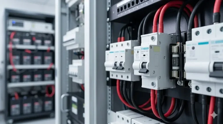
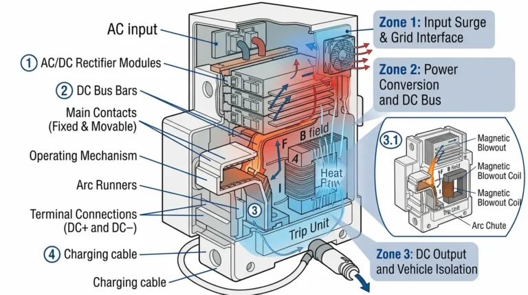
ソーラーヒューズ 専門的なPVシステム設計では、故障を最も低いレベルで隔離し、機器の故障時にシステムの可用性を最大限に維持するよう、協調した保護層を形成します。1回のヒューズ溶断でアレイ全体ではなく、故障したストリングだけを切断する必要があります。これを実現するには、正確な選択性解析、時間-電流曲線の調整、直流配電アーキテクチャ全体への戦略的な配置が必要です。.
このシステム設計ガイドでは、保護エンジニアの視点からソーラーヒューズについて検討します。多層保護戦略(ストリングレベル、コンバイナーレベル、アレイメインレベル)、上流と下流のヒューズ間の選択性要件、I²t エネルギー・レットスルーの計算、故障電流解析、および商業用およびユーティリティスケールの PV 設置の完全な設計手法について分析しています。.
50kW から数 MW 規模の太陽電池アレイを設計する電気エンジニア、システム設計者、および保護専門家にとって、適切なヒューズ調整により、迷惑な停電(故障を迅速に隔離できないサイズの大きいヒューズ)とカスケード故障(通常の状況下で不必要に溶断するサイズの小さいヒューズ)の両方を防ぐことができます。.
💡 デザイン哲学:各保護層は、そのゾーン内の故障に対してのみ動作すべきである。ストリングヒューズはストリング故障を除去し、コンバイナヒューズはコンバイナバス故障を除去し、メインヒューズはアレイからインバータへの故障を除去する。適切な選択性とは、下流の故障除去中に上流のデバイスが閉じたままであることを意味する。.
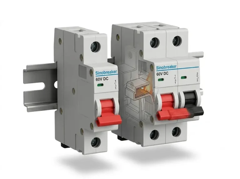
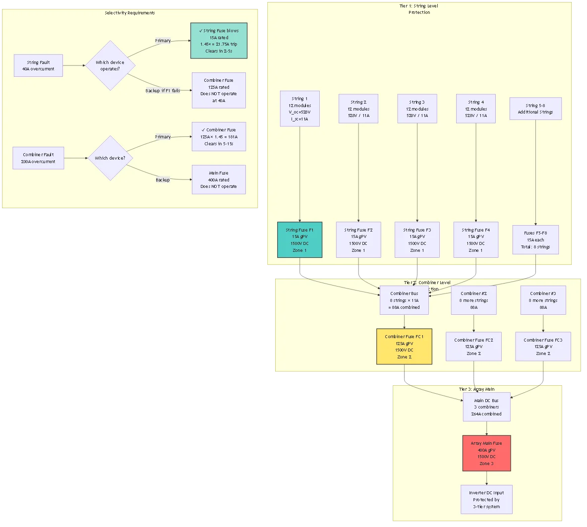
ティア1 - ストリング・レベルのプロテクション:
機能:並列ストリングに影響を与えることなく、個々の欠陥ストリングを切り離す
装置:ストリングごとに個別のヒューズ(通常 10~25A、1000~1500V DC)
保護される障害タイプ:
- ストリング内部短絡(モジュール故障)
- 並列ストリングから遮光/故障ストリングへの逆電流
- ストリングからアースへの障害
- ケーブル絶縁不良
設計パラメータ:
- 定格電流I_fuse ≥ I_sc × 1.56 per NEC 690.9
- 定格電圧: ≥ V_oc_max (最も低温の場合)
- 遮断容量:最低50kA(gPV規格)
- 時間-電流速効性 (I²t < 1000 A²s at 10× In) ティア2 - コンバイナー・レベルのプロテクション:
機能:コンバイナーバスとフィーダーケーブルを次世代機器まで保護
装置:コンバイナー出力ヒューズまたはサーキットブレーカー(通常100~400A)
保護される障害タイプ:
- コンバイナーバスのショート(バスバー故障、端子故障)
- コンバイナーとリコンバイナー/インバーター間のフィーダーケーブルの故障
- 大規模アレイの他のコンバイナーからの逆電流
設計パラメータ:
- 定格電流I ≥ (N_strings × I_sc × 1.25) / 0.80
- ストリングヒューズによる選択性:ストリング故障中は動作しないこと
- 遮断容量:アレイ短絡電流計算に基づく
- 時間-電流:ストリング・ヒューズに対する遅延(I²t > 2× ストリング・ヒューズ)
ティア3 - アレイメインプロテクション:
機能:インバータDC入力前の最終保護、アレイ絶縁
装置:メインDCブレーカーまたはヒューズ(大規模システムでは通常400~3200A)
保護される障害タイプ:
- インバータ入力短絡
- リコンバイナーのDCバス故障
- 主直流配電の地絡
- 系統擾乱時のインバータからのバックフィード
設計パラメータ:
- 定格電流アレイ合計I_sc × 1.25 / 0.80
- コンバイナーで選択:遅延時間-電流特性
- 遮断容量:インバータ位置で利用可能な最大故障電流
- 統合:多くの場合、ディスコネクトスイッチ機能を含む
信頼性のためのオーバーラッピングゾーン:
ゾーン1:個別ストリング
  保護対象ストリングヒューズ(F1)
  バックアップコンバイナーヒューズ(F2)
ゾーン2コンバイナー出力 └─ 保護される:コンバイナーヒューズ(F2) └─ バックアップ:バックアップ:アレイメイン(F3)
ゾーン3アレイからインバータへ └─ プロテクトされる:アレイメイン(F3) └─ バックアップ:バックアップ:インバータ内部保護
設計目標:プライマリ装置はそのゾーン内のフォルトをクリアする。バックアップ装置はプライマリが故障した場合のみ動作する。.
選択率:適切な調整のために
- F2(コンバイナー)定格電流 ≥ 1.6× F1(ストリング)定格電流
- F3(メイン)定格電流≧1.6×F2(コンバイナー)定格電流
- 時間-電流分離:故障電流レベルで最小200-300ms
ヒューズ時間-電流特性:
ソーラーヒューズは逆時間特性に従っており、過電流が大きいと溶断が速くなる。.
カーブのポイント:
1. 従来の非ヒューズ電流 (I_nf):
- ヒューズが溶断せずに2時間耐えられる電流値
- 通常I_nf = 1.25 × I_n
- 例:15Aヒューズ、I_nf = 18.75A
2. 従来のヒューズ電流 (I_f):
- 2時間以内に溶断を引き起こす電流
- 通常I_f = 1.45 × I_n
- 例:15Aヒューズ、I_f = 21.75A
3. 速効領域 (3-20×I_n):
- 一般的なクリア時間:0.1~10秒
- 例:15Aのヒューズを150A(10×)で使用した場合、約0.5秒でクリア。
4. 短絡領域(>20×I_n):
- クリア時間<0.1 秒 - I²t 定格による制限 - 例: 1500A (100×) の 15A ヒューズは ~0.01 秒でクリアーします。
ヒューズ選択の比率法:
選択性を保証するためには、定格電流を守る必要がある:
I_upstream / I_downstream ≥ 1.6(最小比率)
3層システムへの適用:
| ティア | ヒューズ定格 | 選択率 | 検証 |
|---|---|---|---|
| ストリングヒューズ | 15A | ベースライン(1.0) | - |
| コンバイナーヒューズ | 125A | 125 / 15 = 8.3× | 最小 ✓ 8.3 > 1.6 |
| アレイ・メインヒューズ | 400A | 400 / 125 = 3.2× | 最低 ✓ 3.2 > 1.6 |
検証方法:対数紙に時間-電流曲線をプロットする:
- 任意の電流レベルにおいて、上流のヒューズクリアタイムは下流のヒューズより 300ms 以上長くなければならない。
- これにより、上流が溶断するのに十分なI²tを見る前に下流のヒューズが確実にクリアされる
I²tの定義:
I²tは通過エネルギーを表す: ∫ I²(t) dtはA²s(アンペア2乗秒)で測定
物理的な意味:
- 故障が解消する前に下流の機器が吸収したエネルギー
- 導体への加熱効果:温度上昇 ∝ I²t
- 半導体の損傷しきい値:各デバイスの最大I²t定格
調整要件:
I²t_上流 >> I²t_下流(同じ故障電流の場合)
これにより、下流のヒューズが常に最初に溶断し、上流のヒューズを不要な動作から保護します。.
計算例:
ストリング・フォールト:150A(ストリング・ヒューズ定格の10倍)
ストリングヒューズ(15A):
- クリアタイム:0.5秒(メーカー曲線より)
- I²t = I² × t = 150² × 0.5 = 11,250 A²s
コンバイナーヒューズ(125A):
- 電流150A(定格の1.2倍)で、これはI_nfを下回る。
- コンバイナーヒューズが加熱するが溶融しない
- コンバイナーへのI²t寄与: 150² × 0.5 = 11,250 A²s
- コンバイナーヒューズI²t耐量1.2×:~500,000 A²s
- 比率:500,000 / 11,250 = 44× マージン
コンバイナー障害:500A(4×コンバイナーヒューズ定格)
コンバイナーヒューズ(125A):
- クリアタイム:2.0秒(カーブから)
- I²t = 500² × 2.0 = 500,000 A²s
メインヒューズ(400A):
- 電流500A(定格の1.25倍)で、I_nf以下。
- メインヒューズが溶けない
- 1.25倍でI²tに耐える:~5,000,000 A²s
- 比率:5,000,000/500,000=10×マージン✓:5,000,000/500,000=10×マージン
🎯 デザイン・ルール:上流側と下流側のヒューズ間の I²t 比を最低 3:1 に維持することで、あらゆる障害条件下で信頼性の高い選択性を実現。.
システムパラメータ:
- 総容量:500kW
- 電圧:公称1000V DC、最大1100V V_oc_max
- モジュール400W、V_oc = 44V、I_sc = 11.2A
- 構成100ストリング×25モジュール
- 編成:コンバイナー10台×ストリングス各10本
ティア1 - ストリング保護:
I_string = 11.2A × 1.56 = 最小17.5A
選択:20A gPVヒューズ、DC1500V、14×51mm
- 従来のヒューズ電流:20A×1.45=29A(2時間で溶断)
- 速効性:20A×10=200A(0.5秒でブロー)
- 10倍時のI²t15,000 A²s
ティア2 - コンバイナー・プロテクション:
I_combiner = (10ストリングス×11.2A×1.25) / 0.80 = 175A
選択:200A gPVヒューズ、DC1500V、22×58mm
- 従来のヒューズ電流:200A×1.45=290A
- 速効性:200A×5=1000A(1.0秒でブロー)
- I²t(5倍時):800,000 A²s
選択比:200A / 20A = 10×✓(最低1.6を大きく上回る)
ティア3 - アレイメインプロテクション:
I_main = (100ストリングス×11.2A×1.25) / 0.80 = 1750A
選択:2000Aサーキットブレーカー、1500V DC (今のところ、ヒューズは実用的ではない)
- トリップ設定:2000A×1.25=2500A(1.25×オーバーロード)
- 短時間遅延:0.3秒(コンバイナーヒューズが最初にクリアされるようにする)
- 瞬時トリップ10,000A(定格の5倍)
選択比:2000A / 200A = 10×✓
選択性の検証:
ストリング #1 の故障:
- ストリング故障電流:9ストリング×11.2A=100.8A逆方向
- ストリングヒューズF1-1:100.8Aを検知→1.2秒でクリア
- コンバイナーヒューズ FC1:100.8A(0.5×定格)→動作しない。
- メインブレーカー100.8A(0.05×定格)を検出 → 無作動
コンバイナー #1 出力の異常:
- コンバイナーの故障電流:10ストリングス×11.2A=112A
- コンバイナーヒューズFC1:112A(0.56×定格)参照
- 待って... 112A < 200A、ヒューズは切れない!- 問題の特定:コンバイナー出力のボルトフォルトでストリング電流のみ発生
コンバイナーバスの故障:
コンバイナーバス上のボルト締め故障の場合、故障電流は以下のように制限される:
- ストリングヒューズ10 × 20A = 最大200A
- コンバイナーヒューズは、ストリング電流ではなく、ストリングヒューズと協調する必要がある
選択性チェックを修正:
- 一つのストリングが内部でショートした場合:ストリングヒューズは1.2秒で100Aをクリアし、コンバイナーは1.2秒これを見るが溶融しない(I²tマージン80×)。
- コンバイナーバスがショートした場合:10個のストリングヒューズが同時に溶断し、コンバイナーヒューズは合計200Aを見る。
デザイン改善:コンバイナー出力には、ヒューズの代わりにサーキットブレーカーを使用する:
- ブレーカは0.5秒の遅延で250Aのトリップ設定に調整可能
- ストリングヒューズとの協調を提供
- トラブルシューティング用にリセット可能

PVアレイの故障電流は電流制限されている:
ほぼ無限の故障電流を持つ系統電源とは異なり、PVアレイはモジュールの物理的な制約を受ける:
I_fault_max = N_parallel × I_sc × 1.25
どこでだ:
- N_parallel = 故障点に給電する並列ストリングの数
- I_sc = モジュール短絡電流
- 1.25 = 高照度係数
例 - 100 文字列の配列:
メインDCバスでの故障(すべてのストリングが寄与):
- I_fault = 100ストリングス × 11.2A × 1.25 = 1400A
グリッドフォルトと比較する:
- 実用変圧器:1000kVA、1000V、%Z = 5%
- I_fault_grid = 1000 kVA / (1000V × 0.05) = 20,000A
意味合い:PVの故障電流は管理可能であり、大規模なユーティリティ・スケールのアレイでさえ10,000Aを超えることはほとんどない。50kAの遮断容量を持つ標準的なPVヒューズは、5~50倍のマージンを提供します。.
場所 1 - ストリング内部故障:
故障電流 = (N - 1) × I_sc × 1.25(他のストリングからの逆電流)
10弦コンバイナー用:
- I_fault = 9 × 11.2A × 1.25 = 126A
ストリングヒューズ定格:20A
過電流比:126A / 20A = 6.3×
カーブからのクリアタイム0.8秒
場所 2 - コンバイナーバスの故障:
ストリング・ヒューズによって制限される故障電流:
- I_fault ≤ N_strings × I_fuse_rating
- 例:10×20A=最大200A
コンバイナーヒューズの定格が200Aの場合、これはちょうど定格の1.0倍である。コンバイナーの定格を低くするか(125-160A)、または調整可能なトリップ付きサーキットブレーカーを使用する必要があります。.
場所 3 - メイン DC バス故障:
すべてのコンバイナーからの故障電流:
- I_fault = N_combiners × (N_strings × I_sc × 1.25)
- 例:コンバイナー10個×ストリング10本×11.2A×1.25=1400A
メインブレーカー定格:2000A
比率:1400A / 2000A = 0.7×
問題点:過負荷-故障電流がブレーカーを確実にトリップさせない。メインブレーカの定格を1600Aに下げるか、感度の高い地絡検出装置を取り付ける必要がある。.
NEC 690.5 漏電保護:
アレイの対地電圧が50Vを超える50kWを超えるすべてのシステムに必要。.
検出方法:
直流システムと接地間の絶縁抵抗を監視する:
- ノーマル:>1 MΩ以上
- 警告<500 kΩ - フォルト:<10 kΩ
漏電電流:
I_ground = V_system / (R_fault + R_system)
例
- システム電圧:1000V DC
- 地絡抵抗:10Ω(ボルトによる地絡)
- システム抵抗:2Ω(ワイヤー、接続部)
- I_ground = 1000V / 12Ω = 83A
チャレンジ83A の地絡は 2000A のメインブレーカをトリップしない場合がある。専用の漏電保護リレーが必要。.
ソリューション:残留電流装置(漏電遮断器)または地絡保護リレーを設置する:
- プラス電流とマイナス電流のアンバランスを検出
- 典型的な設定:人員保護用感度300mA、機器保護用感度5A
- 接地電流が設定値を超えると、補助トリップを介してメインブレーカを開く

ヒューズとブレーカーを混在させる場合:
| 所在地 | デバイス・タイプ | 根拠 |
|---|---|---|
| 文字列レベル | ヒューズ | 低コスト、コンパクト、高精度I²t、単回使用可 |
| コンバイナー出力 | サーキットブレーカー | リセット可能、調整可能なトリップ、頻繁なアクセス |
| 配列メイン | サーキットブレーカー | 大電流容量、ディスコネクト機能、メーター機能 |
調整用ヒューズ・ツー・ブレーカー:
ブレーカには、調節可能な温度(I_t)および磁気(I_mag)トリップ設定があります:
例:
- ストリング・ヒューズ:20A
- コンバイナーブレーカー125A、調整可能サーマル0.8-1.0× In、マグネット5-10× In
選択性の設定:
- サーマル:1.0×(1.25×の場合、60分で125Aトリップ)
- マグネット:8×(1000A瞬間トリップ)
- 短時間ディレイ:0.5秒
検証する:
- ストリング故障126A:ストリングヒューズは0.8秒でクリア、ブレーカーはこれを見るがサーマルには達しない(0.8秒 << 60分) ✓ - コンバイナー故障500A:ブレーカは 1000A で磁化されているため、即座にトリップしない。500A のサーマルは 8-10 秒でクリアされる ✓ - 主故障 1500A:主故障 1500A: ブレーカが瞬時にトリップ(<0.1s) ✓ - コンバイナ故障
周囲温度の影響:
ヒューズもブレーカーも温度によって減衰するが、その速度は異なる:
| 周囲温度 | ヒューズのディレーティング | ブレーカーのディレーティング | 調整への影響 |
|---|---|---|---|
| 25°C (STC) | 1.00 (nominal) | 1.00 (nominal) | Designed coordination valid |
| 50°C | 0.90 | 0.93 | Coordination maintained |
| 70°C | 0.80 | 0.85 | Coordination slightly degraded |
High Temperature Risk:
At 70°C combiner box temperature:
– String fuse effective rating: 20A × 0.80 = 16A
– Combiner breaker effective rating: 125A × 0.85 = 106.25A
– Selectivity ratio: 106.25 / 16 = 6.6× (was 6.25× at 25°C)
Coordination improves slightly at high temperature (both devices trip faster but ratio maintained).
Cold Temperature Issue:
At -20°C:
– Module V_oc increases 13-15%
– Module I_sc increases 2-3%
– Fuse sees higher inrush during morning startup
Design practice: Size fuses based on I_sc at 25°C × 1.25 (high irradiance). This inherently provides margin for cold temperature I_sc increase.
N+1 Combiner Architecture:
For utility-scale systems requiring maximum availability:
Standard Design:
– 10 combiners × 100A = 1000A total
– Main breaker: 1250A
– Single combiner failure: 10% capacity loss
N+1 Design:
– 11 combiners × 100A = 1100A total (10% excess)
– Main breaker: 1250A
– Single combiner failure: System continues at full rated capacity
Protection Coordination:
– Each combiner: 100A fuse or breaker
– Main: 1250A breaker with monitoring
– Ground fault: 5A sensitive relay on each combiner
コストへの影響:
– Additional combiner: $3,000-5,000
– Additional cabling: $1,500-2,500
– Total: +$5,000 for 500kW system (+$10/kW)
– Benefit: Zero downtime during combiner maintenance/failure

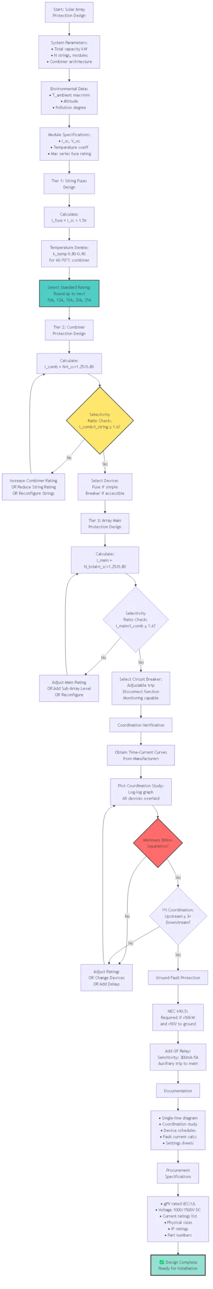
1. System Architecture Definition:
– [ ] Total array capacity (kW)
– [ ] Number of strings and modules per string
– [ ] Number of combiner boxes and strings per combiner
– [ ] Inverter(s) DC input specifications
– [ ] Voltage range: V_mpp, V_oc_min, V_oc_max
– [ ] Module specifications: I_sc, I_mpp, temperature coefficients
2. Environmental Parameters:
– [ ] Maximum ambient temperature in combiner boxes
– [ ] Minimum ambient temperature (for V_oc calculation)
– [ ] Altitude (if >2000m, apply derating)
– [ ] Pollution degree (coastal, industrial, clean)
3. Code Compliance Requirements:
– [ ] NEC 690.9 overcurrent protection
– [ ] NEC 690.5 ground fault protection (if >50kW)
– [ ] State/local amendments to NEC
– [ ] Utility interconnection requirements
4. Tier 1 – String Fuse Selection:
– [ ] Calculate: I_fuse ≥ I_sc × 1.56
– [ ] Apply temperature derating
– [ ] Select standard gPV rating
– [ ] Verify voltage rating ≥ V_oc_max
– [ ] Check module datasheet max series fuse rating
– [ ] Specify physical size (10×38, 14×51, 22×58)
– [ ] Select fuse holder (IP rating, wire termination capacity)
5. Tier 2 – Combiner Protection Selection:
– [ ] Calculate: I_comb = (N_strings × I_sc × 1.25) / 0.80
– [ ] Verify selectivity ratio vs string fuses (≥1.6×)
– [ ] Check I²t coordination
– [ ] Decide: Fuse or circuit breaker?
– [ ] If breaker: Set thermal and magnetic trip points
– [ ] Verify breaking capacity ≥ maximum fault current
6. Tier 3 – Array Main Protection:
– [ ] Calculate: I_main = (N_total_strings × I_sc × 1.25) / 0.80
– [ ] Verify selectivity ratio vs combiner devices (≥1.6×)
– [ ] Select circuit breaker (typically, due to high current)
– [ ] Configure adjustable trip settings
– [ ] Integrate disconnect and monitoring functions
– [ ] Add ground fault protection relay (NEC 690.5)
7. Coordination Verification:
– [ ] Obtain time-current curves from all manufacturers
– [ ] Plot on log-log coordination study
– [ ] Verify 300ms minimum separation at all fault current levels
– [ ] Check I²t coordination: upstream ≥ 3× downstream
– [ ] Verify selectivity at maximum and minimum fault currents
8. Documentation:
– [ ] Single-line diagram showing all protection devices
– [ ] Coordination study with time-current curves
– [ ] Device schedules (rating, type, manufacturer, part number)
– [ ] Fault current calculations for each location
– [ ] Settings sheets for adjustable breakers
9. Procurement Specifications:
– [ ] Fuse type: gPV per IEC 60269-6 または UL 2579
– [ ] Voltage rating: 1000V or 1500V DC
– [ ] Current ratings: [list each tier]
– [ ] Physical sizes: [specify 10×38, 14×51, etc.]
– [ ] Fuse holder IP rating: IP65 minimum outdoor
– [ ] Circuit breaker: DC-rated, electronic trip, communication capable
10. Commissioning Verification:
– [ ] Visual inspection: Correct fuses installed in each position
– [ ] Polarity check: Positive and negative correctly identified
– [ ] Torque verification: Terminals tightened to specification
– [ ] Insulation resistance test: >1 MΩ system-to-ground
– [ ] Function test: Trip one string fuse, verify others continue
– [ ] Ground fault test: Inject test signal, verify relay operation
Selectivity requires minimum 1.6:1 current rating ratio between upstream (combiner) and downstream (string) fuses. Example: 15A string fuses require ≥24A combiner fuses; in practice, use next standard rating (25A minimum). Additionally, verify I²t coordination: at any fault current level, upstream fuse’s I²t withstand must be >3× downstream fuse’s let-through I²t. Plot manufacturer time-current curves on log-log coordination study to verify >300ms separation at all fault currents. If selectivity fails, increase combiner fuse rating, reduce string fuse rating, or change combiner to adjustable circuit breaker with time delay.
This creates coordination problems—the fuse won’t reliably clear faults within its protection zone. Example: combiner bus fault produces 180A, but combiner fuse rated 200A. At 0.9× rating, fuse takes 4+ hours to blow (far too slow). Solutions: (1) Reduce fuse rating to ensure fault current exceeds 1.25× rating minimum; (2) Replace fuse with circuit breaker having adjustable trip set at 1.25× expected fault current; (3) Install sensitive fault detection relay that trips breaker at lower currents. For ground faults producing <25% of rated current, dedicated ground fault relays (300mA-5A sensitivity) are mandatory per NEC 690.5.
No—each string’s fuse must match its specific I_sc. Mixed-module arrays require separate calculations: String A with I_sc=11A needs 11×1.56=17.16A → 20A fuse; String B with I_sc=9A needs 9×1.56=14.04A → 15A fuse. Using oversized fuses (20A for all strings) leaves lower-current strings underprotected against reverse current. Using undersized fuses causes nuisance trips on high-current strings during cloud-edge enhancement. Document each string type clearly on single-line diagrams and label fuse positions accordingly. For maintenance simplicity, some designers standardize on highest-I_sc fuse rating across all strings, accepting slight cost increase for lower-I_sc string overprotection.
High combiner box temperatures (60-70°C rooftop installations) reduce both fuse and breaker capacity by 15-20%. Critical design impact: calculate all ratings at expected maximum temperature, not 25°C standard. Example: 20A fuse at 70°C effectively becomes 16A. Fortunately, both upstream and downstream devices derate proportionally, maintaining selectivity ratios. However, fault clearing times increase at high temperatures (element takes longer to reach melting point), slightly degrading protection speed. Design conservatively: size string fuses for coldest temperature I_sc increase (×1.13 at -20°C) but verify capacity at hottest ambient using temperature derating factors from manufacturer datasheets.
Inverter manufacturers specify maximum let-through I²t their semiconductor switches can withstand without damage—typically 10,000-50,000 A²s for utility-scale inverters. Select fuses with let-through I²t (at prospective fault current) <50% of inverter I²t rating for safety margin. Example: Inverter max I²t = 40,000 A²s at 1000A fault current. Fuse let-through at 1000A (from manufacturer curve): 8,000 A²s. Ratio: 40,000/8,000 = 5× margin ✓. If insufficient margin, use faster-acting fuse, reduce fuse rating (increases I²t withstand relative to fault current), or add current-limiting reactors upstream of inverter.
NEC 690.9(A) requires overcurrent devices in all ungrounded DC conductors. For typical ungrounded (floating) PV systems: fuse BOTH positive and negative. For grounded systems where negative is bonded to earth: fuse only positive (NEC 690.9(B) exception). However, modern practice increasingly fuses both conductors even in grounded systems for several reasons: (1) symmetry simplifies maintenance and troubleshooting; (2) provides protection regardless of where ground fault occurs; (3) facilitates future conversion to ungrounded configuration; (4) cost difference minimal (2× fuses instead of 1×). Large utility systems may omit negative fuses for cost savings in grounded designs, but residential/commercial systems typically fuse both.
Inverters contain internal DC input protection (typically electronic monitoring with IGBT shutdown, sometimes backup fuses). Proper coordination ensures external array fuses clear first for array faults, inverter protection activates only for internal inverter faults. Design approach: (1) Obtain inverter maximum DC input current specification (e.g., 250A continuous); (2) Size array main fuse/breaker for 250A × 1.25 = 313A → use 315A or 400A rating; (3) Verify inverter internal protection set points (typically 1.5-2× continuous rating = 375-500A); (4) At array fault producing 300A, external 315A fuse clears in 30-120 seconds, inverter sees this but doesn’t trip (below 375A threshold) ✓. Inverter protection provides backup if external fuse fails and handles internal DC link capacitor inrush or failure modes.
Solar fuses system design transcends simple device selection—proper protection requires multi-tier architecture with precisely coordinated selectivity ensuring faults clear at the lowest level without cascading to upstream devices. Effective designs isolate individual string failures while maintaining array availability, protect expensive inverter electronics through I²t limiting, and comply with NEC ground fault detection requirements for systems >50kW.
Critical Design Principles:
Three-Tier Architecture: String-level fuses (15-25A) protect individual PV strings and provide reverse current isolation. Combiner-level fuses or breakers (100-250A) protect combiner bus and feeders. Array main breakers (400-3200A) provide final protection before inverter with disconnect and monitoring functions. Each tier sized using NEC 690.9 methodology with 1.56× multiplier for strings, (N×I_sc×1.25)/0.80 for combiners.
Selectivity Requirements: Minimum 1.6:1 current rating ratio between adjacent tiers ensures downstream devices clear first. Verify coordination with time-current curves: >300ms separation at all fault current levels. I²t coordination critical: upstream device I²t withstand ≥3× downstream device let-through at common fault currents.
Fault Current Analysis: PV arrays are current-limited—maximum fault current = N_parallel × I_sc × 1.25. Unlike grid faults (20-100 kA), PV faults typically <10 kA even in utility-scale systems. This simplifies protection: standard 50 kA gPV fuses provide substantial margin. However, limited fault currents create challenges coordinating oversized protection devices—must size carefully to ensure fault current exceeds 1.25× device rating. Temperature and Environmental Corrections: Size all devices considering maximum combiner box temperature (60-70°C typical rooftop). Apply 15-20% capacity derating for high temperatures. Simultaneously verify cold-temperature V_oc doesn’t exceed voltage ratings. Ground fault protection mandatory >50kW per NEC 690.5—sensitive relays (300mA-5A) required as standard overcurrent devices may not detect low-magnitude ground faults.
For protection engineers and system designers, coordinated solar fuses enable safe, reliable PV systems that maintain availability during faults and protect personnel and equipment throughout 25-30 year project lifecycles.
Related Protection Engineering Resources:
- ソーラーパネル・ヒューズの基礎知識 – Fundamental fuse technology
- PVコンバイナーボックスの設計 - コンバイナーの仕様
- DC Circuit Breaker Coordination – Breaker-based protection
Engineering Services: SYNODE provides protection coordination studies for solar projects >500kW including time-current curve analysis, fault current calculations, and device selection optimization. Contact our power systems engineering team for coordination study services and NEC compliance verification.
最終更新日 2025年10月
著者 SYNODE Protection Engineering Team
テクニカル・レビュー Professional Engineers (PE), NABCEP PV Designers
参照規格 NEC第690条:2023, IEC 60269-6:2016, IEEE 1547:2018