주소
304 북쪽 추기경
세인트 도체스터 센터, MA 02124
근무 시간
월요일~금요일: 오전 7시~오후 7시
주말: 주말: 오전 10시 - 오후 5시
주소
304 북쪽 추기경
세인트 도체스터 센터, MA 02124
근무 시간
월요일~금요일: 오전 7시~오후 7시
주말: 주말: 오전 10시 - 오후 5시

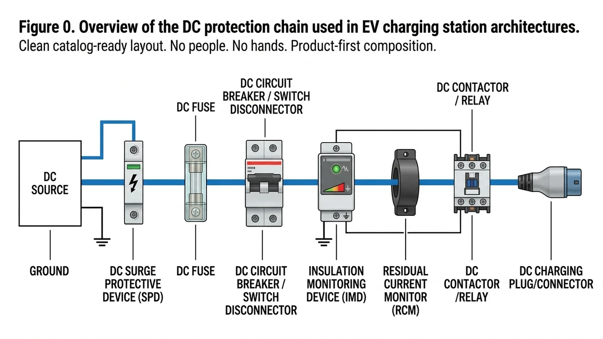
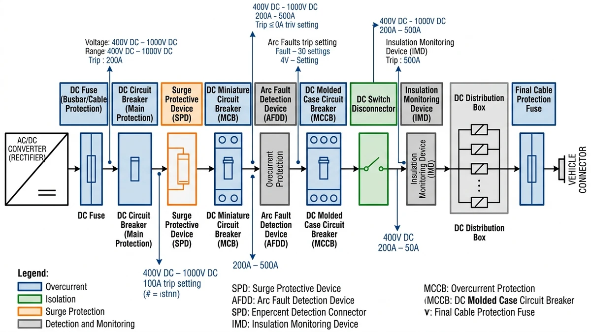
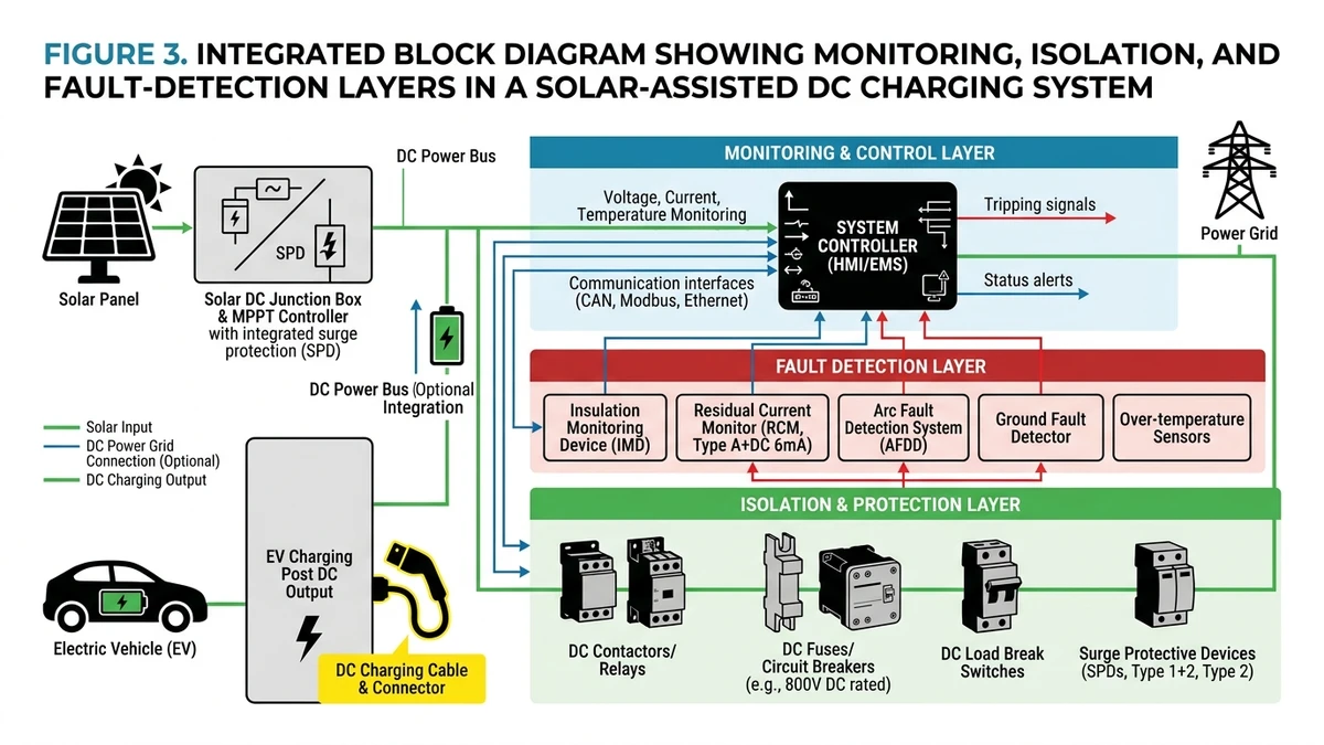
DC protection components for EV charging stations form a layered defense system that guards against overcurrent, arc faults, voltage surges, and isolation failures across 400–1000 VDC bus architectures. A 2024 field review of fast-charging corridors in Zhejiang Province found that stations lacking coordinated DC protection experienced 3× more unplanned downtime than those with fully specified protection chains.
According to IEC 60364-7-722, every DC charging circuit requires coordinated protection from the AC/DC converter output through to the vehicle connector — no single device covers the full fault spectrum.
The protection stack typically includes these 10 components:
For a deeper look at how these devices work together in a real charging architecture, see the guide to DC circuit breaker selection for EV stations on the Sinobreaker website.
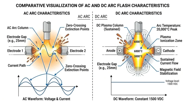
DC protection in EV charging stations faces a fundamentally different challenge than AC protection. In AC systems, current naturally crosses zero 100–120 times per second, giving circuit breakers repeated opportunities to extinguish an arc. DC current has no zero crossing, so once an arc forms, it can sustain itself unless the device actively forces extinction.
In an AC circuit, arc plasma cools and deionizes at each current zero. In a DC circuit operating at 1000 VDC, the arc can burn continuously at temperatures exceeding 6000°C. The breaker must generate an arc extinction voltage higher than the system voltage to force current to zero. That is why DC devices rely on magnetic blowout structures, ceramic arc chutes, and longer contact travel than comparable AC products.
The energy involved is substantial. In a 1000 VDC fast-charging bus with low-impedance source connections, prospective short-circuit current can reach 20–50 kA within the first millisecond of a fault. A 60 MW DC charging hub project in Zhejiang Province in 2024 documented arc fault events where improperly rated components failed to interrupt within 200 ms, causing busbar damage that took the station offline for 11 days. Properly rated devices with verified breaking capacity under IEC 60947-2 cleared the same fault class in under 15 ms.
An AC-rated breaker carries no guarantee of DC performance. IEC 60898-2 addresses DC miniature circuit breakers with separate voltage and breaking-capacity requirements for DC service. A breaker rated 10 kA at 230 VAC may only achieve 3–5 kA at 500 VDC. This is why every component on this list must carry a DC-specific rating, and why using AC hardware on a DC bus remains one of the most common causes of field failure.
The DC MCB handles branch-level overcurrent protection. For smaller subcircuits, a 63 A / 1000 VDC rating is often sufficient, while larger DC fast-charging architectures may require devices rated to 1500 VDC with minimum breaking capacity around 10 kA under IEC 60898-2. If the MCB is undersized, it may fail to interrupt a fault arc cleanly, allowing damaging thermal stress on conductors and busbars.
DCFC and ultra-fast chargers typically need a DC MCCB at the main incoming feed. Typical breaking capacity ranges from 25–65 kA at 1000 VDC under IEC 60947-2. In a 120 kW DCFC installation in Zhejiang Province, undersized MCCBs failed pre-commissioning fault tests; replacing them with properly rated 1000 VDC / 36 kA units resolved the issue. The risk of underspecification here is severe: nuisance tripping during inrush on one end, or failure to clear a bolted fault on the other.
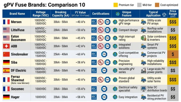
DC fuses provide fast current limiting where breakers alone may not react quickly enough. High-power stations with prospective fault currents up to 50 kA often use gPV or semiconductor-grade gR fuses to protect semiconductors and cabling. IEC 60269-6 governs gPV fuse performance at rated voltage. Using slow-blow or AC-rated fuses in a DC circuit can lead to non-clearing faults or welded elements.
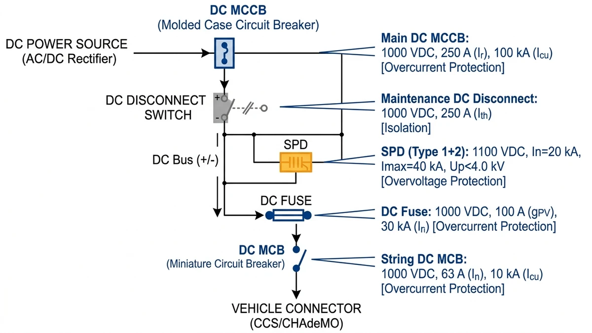
An SPD clamps transient overvoltages caused by lightning and switching events before they reach sensitive power electronics. For DC fast chargers, select a Type 2 or Type 1+2 DC SPD with maximum continuous operating voltage (Uc) at least 1.2× the bus voltage and a low protection level (Up), typically not exceeding 2.5 kV for many 1000 VDC systems under IEC 61643-11. If surge protection is underspecified, repeated transient stress can shorten the life of IGBT modules, control boards, and communications electronics.
Every charging station needs a manual isolation point for maintenance and lockout/tagout. A DC 스위치 단로기 rated for the station’s full operating voltage provides visible, safe isolation, but it is not a substitute for fault interruption. If technicians operate a non-load-break isolator under the wrong conditions, contact welding and loss of isolation capability can follow.
[Expert Insight]
– Coordinate fuse let-through energy with downstream semiconductor limits, not just cable ampacity.
– Place the SPD as physically close as possible to the protected electronics to reduce lead-induced voltage rise.
– Verify MCCB polarity and terminal orientation on DC models; some devices are line/load sensitive in DC applications.
– Treat the switch disconnector as an isolation device in the sequence, not as the primary fault-clearing element.
A DC charging system needs continuous supervision for leakage or insulation breakdown between the DC bus and earth. In unearthed DC systems, insulation monitoring devices are typically selected per IEC 61557-8 and should respond to deteriorating insulation resistance before a dangerous fault develops. In grounded architectures, residual-current or ground-fault protection may be used according to the charger design and applicable standard.
Arc fault detection addresses a failure mode that conventional overcurrent devices often miss: a high-impedance series or parallel arc that does not draw enough current to trip a breaker quickly. In charging stations with vibration, connector wear, or repeated mating cycles, arc detection adds a useful layer of fire prevention by identifying the signature of unstable conduction before damage spreads.
Real-time monitoring of voltage, current, and energy throughput supports both billing accuracy and predictive maintenance. Look for meters with ±0.5% accuracy class and RS-485 or Modbus RTU communication so the charger can feed data into SCADA, EMS, or local maintenance dashboards. Good monitoring does not replace protection, but it often reveals overload patterns, imbalance, and abnormal thermal behavior before an outage occurs.
그리고 DC 배전함 is the integration point that houses multiple protective devices in a properly rated enclosure. For outdoor EV infrastructure, enclosure rating, busbar spacing, thermal management, and cable-entry sealing matter as much as the devices inside. A poorly designed cabinet can undermine otherwise well-specified protection by trapping heat or allowing moisture ingress.
At the point of connection, a dedicated busbar or cable protection fuse provides the final layer against catastrophic short circuits on downstream conductors. This last-line fuse is especially valuable where cable routing, connector transitions, or parallel bus structures create localized fault risk that upstream devices may not limit quickly enough.
Clamping voltage Up must satisfy: Up ≤ 80% of the equipment’s rated impulse withstand voltage (Uiw). For a charger rated at Uiw = 4 kV, select an SPD with Up ≤ 3.2 kV.
[Expert Insight]
– Put insulation monitoring alarms into the station EMS so maintenance sees degradation trends before trips occur.
– In outdoor cabinets, check condensation risk and heater/ventilation strategy alongside enclosure IP rating.
– For metering, confirm communication protocol mapping early; many field delays come from Modbus register mismatches, not hardware faults.
| 구성 요소 | Level 2 (≤19.2 kW / ≤48 VDC–1000 VDC) | DCFC 50–150 kW (typically 500–1000 VDC) | Ultra-Fast 200–360 kW (typically 800–1500 VDC) | Key Standard |
|---|---|---|---|---|
| DC MCB | 63–125 A, 750 VDC | 160–250 A, 1000 VDC | Not recommended — use MCCB | IEC 60898-2 |
| DC MCCB | 선택 사항 | 250–630 A, 1000 VDC, Icu ≥ 25 kA | 630–1600 A, 1500 VDC, Icu ≥ 50 kA | IEC 60947-2 |
| DC 퓨즈(gPV) | 10–63 A, 1000 VDC | 100–315 A, 1000 VDC | 315–800 A, 1500 VDC | IEC 60269-6 |
| DC 스위치 단로기 | 63–125 A, 1000 VDC | 250–630 A, 1000 VDC | 800–1600 A, 1500 VDC | IEC 60947-3 |
| 서지 보호 장치(SPD) | Up (protection level) ≤ 2.5 kV, Type 2 | Up ≤ 2.5 kV, Type 1+2 | Up ≤ 2.5 kV, Type 1+2, Iimp ≥ 12.5 kA | IEC 61643-11 |
| DC Contactor | 80–125 A, 1000 VDC | 250–500 A, 1000 VDC | 500–1000 A, 1500 VDC | IEC 60947-4-1 |
| Pre-charge Resistor | Low inrush, ≤ 10 Ω | 5–20 Ω, rated ≥ 200 W | 1–10 Ω, rated ≥ 500 W | IEC 60947-4-1 |
| Ground Fault Monitor (IMD) | Required per IEC 61851-1 | Required, response ≤ 30 ms | Required, response ≤ 10 ms | IEC 61557-8 |
| Current Sensor / Shunt | ±1% accuracy, ≤ 200 A | ±0.5% accuracy, ≤ 600 A | ±0.2% accuracy, ≤ 1200 A | IEC 60051 |
| DC Distribution Box | IP54, ≤ 1000 VDC | IP55, ≤ 1000 VDC, busbar rated ≥ 630 A | IP65, 1500 VDC, busbar rated ≥ 1600 A | IEC 62208 |
Move down a column to see how a single component scales with tier. A 50 kW DCFC station operating at 1000 VDC typically needs an MCCB rated at 250 A minimum with Icu ≥ 25 kA, while an ultra-fast 360 kW charger at 1500 VDC calls for 1500 VDC-rated DC fuses and higher-impulse SPDs. A 2024 deployment survey of DCFC stations in Zhejiang Province found that undersized SPDs, specified to Level 2 assumptions rather than DCFC duty, were a leading cause of surge-related downtime during summer lightning season. For general EV charging installation requirements, IEC references remain central, and broader charging guidance is also summarized by the International Energy Agency at https://www.iea.org/reports/global-ev-outlook-2024.
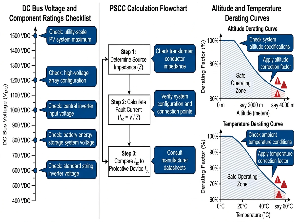
Before you compare catalogs, lock down the few upstream values that determine whether every downstream selection will be right or wrong.
Voltage architecture varies substantially across charging platforms. Level 2 systems may sit lower, while modern fast chargers increasingly operate at 800–1000 VDC and some ultra-fast designs push higher. Every protection component — from branch breakers to fuses and isolators — must have a rated voltage that meets or exceeds the maximum system voltage, including tolerance and transient conditions. Specifying a 750 VDC-rated device on an 800 VDC bus is a compliance problem, not a cost optimization.
PSCC is the fault current a device must interrupt at its installed location. For a typical 150 kW fast charger with a 1000 VDC bus, PSCC at the main DC busbar may reach 15–25 kA. Under IEC 60947-2, the selected breaker’s ultimate breaking capacity must exceed that value at the node where it is installed. A 2023 installation across six highway charging plazas in Zhejiang Province found that half the sites had breakers specified with Icu ratings 30–40% below actual PSCC, forcing replacement before commissioning.
Nameplate ratings usually assume standard conditions such as 2000 m altitude and 40°C ambient. Above those thresholds, dielectric strength and heat dissipation both degrade. IEC 60664-1 provides the framework for insulation coordination at altitude.
High-altitude and high-heat sites push protection devices into thermal and insulation stress faster than many teams expect. Cross-check breaker and fuse selections against the manufacturer’s derating curves before freezing the BOM.
Once your voltage, fault-current, and installation conditions are defined, building the protection stack becomes a matter of matching each layer to the real operating risk.
Selecting the right DC protection components means matching every device — from branch protection to surge suppression and isolation — to the station’s voltage class, available fault current, and compliance target. Sinobreaker’s product range covers the full protection stack, with devices rated from 250 VDC up to 1500 VDC and breaking capacities reaching 100 kA, engineered for charging infrastructure applications.
Explore the product pages on Sinobreaker to find suitable options for projects ranging from compact DC chargers to multi-bay ultra-fast hubs. For a deeper technical reference on coordination logic, the EV charging station protection guide on Sinobreaker walks through selection criteria by power tier and fault scenario.
There is no single most important device because DC charger safety depends on a coordinated chain. Main breakers, branch protection, surge control, isolation, and fault monitoring each cover different failure modes.
No. AC breakers are not automatically suitable for DC duty because DC arcs do not self-extinguish at current zero, so the breaker needs a verified DC voltage and breaking-capacity rating.
Start with the prospective short-circuit current at the exact installation point, then choose an MCCB with Icu above that value at the required DC voltage. Margin is important, especially on high-power chargers with low source impedance.
Yes, especially outdoor stations exposed to lightning or switching transients. Without a correctly selected SPD, repeated surges can damage power modules, control boards, and communication hardware.
A fuse is typically faster and more current-limiting, while a breaker is resettable and better suited for repeated operation and coordinated switching schemes. Many charging stations use both because they solve different protection problems.
At higher elevations, insulation withstand performance drops and cooling becomes less effective. That combination can reduce safe operating margins unless the device is derated correctly.
Yes. Insulation monitoring is a core safety function in unearthed DC architectures because it detects declining isolation before it turns into a dangerous fault or forced outage.