주소
304 북쪽 추기경
세인트 도체스터 센터, MA 02124
근무 시간
월요일~금요일: 오전 7시~오후 7시
주말: 주말: 오전 10시 - 오후 5시
주소
304 북쪽 추기경
세인트 도체스터 센터, MA 02124
근무 시간
월요일~금요일: 오전 7시~오후 7시
주말: 주말: 오전 10시 - 오후 5시

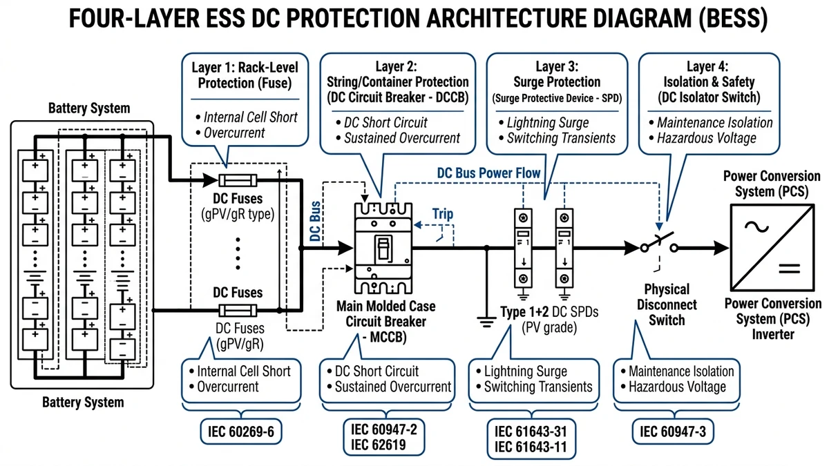
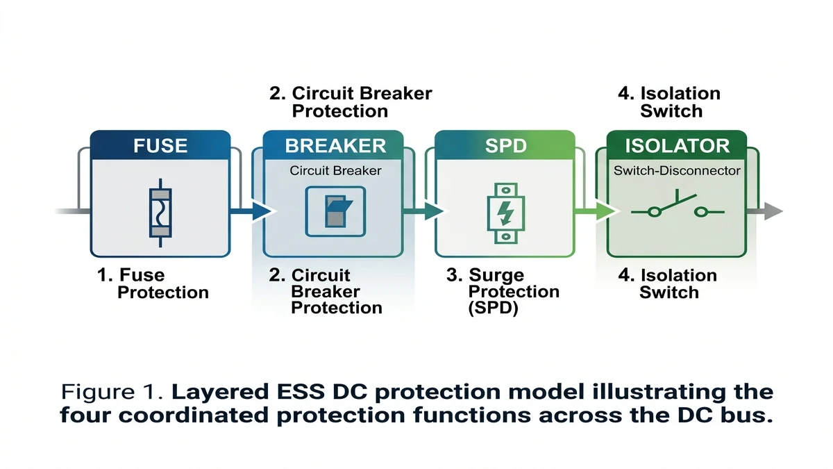
Reliable ESS DC protection starts with a layered architecture, because no single device can safely manage every fault condition on a 48–1500 VDC battery system. ESS DC protection combines four coordinated layers — fuse, DC circuit breaker, surge protective device (SPD), and isolator — each assigned a distinct response role across overcurrent, short-circuit, transient overvoltage, and safe isolation.
A 20 MWh lithium-ion ESS project in Guangdong (2024) demonstrated this clearly: when only breakers and fuses were installed without SPDs, transient overvoltages from grid switching events caused repeated BMS communication failures — a fault mode invisible to overcurrent protection alone.
| Layer | 구성 요소 | 주요 기능 | Key Standard |
|---|---|---|---|
| 1 — Overcurrent | gPV / DC fuse | Sacrificial interruption of sustained overcurrent (>1.6× In) | IEC 60269-6 |
| 2 — Short-circuit & switching | DC 회로 차단기 | Resettable fault interruption up to rated Icu; bidirectional DC arc quenching | IEC 60947-2 |
| 3 — Transient suppression | surge protective device (SPD) | Clamping transient overvoltages to Up ≤ 2.5 kV within nanoseconds | IEC 61643-11 |
| 4 — Safe isolation | DC 스위치 단로기 | Visible break isolation for maintenance; ≥ 1.5× rated voltage clearance | IEC 60947-3 |
Protection coordination works only when each layer absorbs the type and amount of energy it was designed for before passing residual stress downstream. The fuse handles slower, high-energy overcurrents that would age a breaker’s thermal mechanism. The breaker provides resettable fault clearing and selectivity. The SPD clamps sub-millisecond transients that neither upstream device detects. The isolator then provides the zero-energy state needed for safe maintenance access.
The coordination margins between layers are covered in detail in the ESS battery storage protection guide.
The first protection decision in an ESS string is often the most unforgiving, because fuse sizing determines whether a fault is contained in milliseconds or escalates into thermal damage. In ESS DC protection, the fuse is the first and fastest line of defense, clearing short-circuit current before fault energy can weld breaker contacts or ignite vented battery gases. A properly sized gPV or gR fuse can respond in under 10 ms at 10× rated current, faster than any mechanical breaker.
The key coordination value in ESS applications is I²t, the let-through energy a fuse passes before clearing. IEC 60269-6 defines fuse-link performance for photovoltaic and battery-related DC applications, including pre-arcing I²t and total clearing I²t at rated voltage. For the stack to remain coordinated, the fuse’s total clearing I²t must stay below the withstand I²t of every downstream component, including cable insulation, busbar joints, and breaker contacts.
For a 1000 VDC battery string with a prospective short-circuit current of 20–30 kA, a correctly coordinated fuse limits let-through energy to roughly 104–105 A²s, keeping downstream thermal stress within cable and breaker ratings. Oversizing the fuse — even by one current rating step — can push clearing I²t above the cable’s withstand threshold, turning a survivable fault into a fire event.
Battery systems impose fuse selection constraints that are stricter than in one-way PV strings:
A 200 MWh lithium-iron-phosphate ESS project in Inner Mongolia (2023) reported contact welding failures in string breakers during commissioning load tests. Post-analysis showed the installed fuses were rated for PV unidirectional duty only; replacing them with bidirectional-rated DC fuses eliminated the welding events.
[Expert Insight]
– Check fuse datasheets for both voltage polarity arrangement and declared DC application class; “PV” alone does not confirm battery-duty suitability.
– In containerized ESS rooms, measure actual enclosure temperature at the fuse holder, not just ambient outside the cabinet.
– Verify the fuse holder and terminations carry the same DC voltage rating as the fuse-link; mixed ratings are a common hidden failure point.
Coordination examples are covered in the ESS battery storage protection guide. String-level fuse selection also connects directly to upstream gPV fuse ratings when the ESS shares a DC bus with a co-located PV array.
Once short-circuit backup is established, the next priority is selective interruption, so only the faulted section drops out instead of the entire battery block. A DC circuit breaker is the resettable protection layer in the ESS stack, handling sustained overloads and fault isolation at the string, rack, and busbar level.
IEC 60947-2 governs industrial DC circuit breakers, including Icu and Ics ratings. In ESS procurement, these two values are often confused. A breaker chosen only by Icu may survive one fault but no longer be suitable for service. For systems expected to remain operational after a fault, Ics should be at least 75% of Icu.
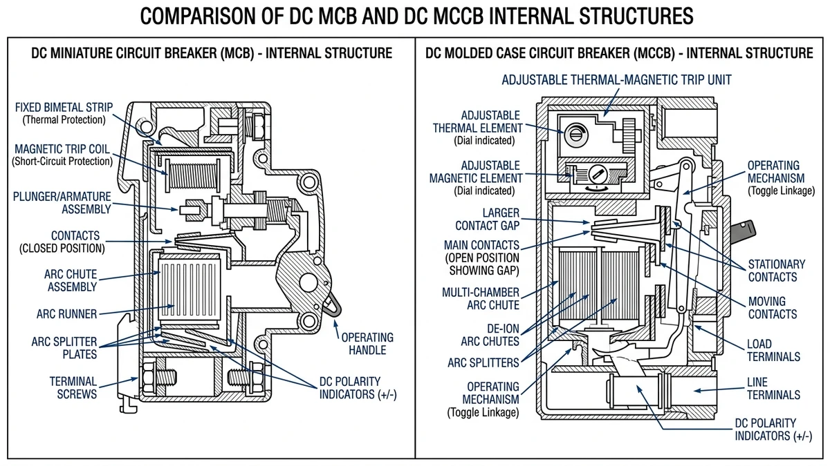
In a 20 MWh lithium-ion ESS project in Guangdong (2024), standard MCBs rated at 6 kA failed pre-qualification testing against an 18 kA prospective fault current on an 800 VDC busbar. The project shifted to MCCBs with adjustable thermal-magnetic trip units and a minimum Icu of 25 kA at 800 VDC.
| 매개변수 | DC MCB | DC MCCB |
|---|---|---|
| Typical current range | 1–125 A | 16–1600 A |
| 차단 용량(Icu) | 6-10 kA | 16–100 kA |
| Trip adjustment | 수정됨 | Adjustable (thermal + magnetic) |
| ESS application | String-level, BMS aux circuits | Rack, cluster, busbar protection |
| 정격 전압 | 최대 1000VDC | 최대 1500VDC |
| Selective coordination | 제한적 | Full zone selectivity |
For string-level protection in ESS racks, DC MCB rated at 1000 VDC with B or C trip curves cover many residential and C&I battery applications. C-curve devices, with a 5–10× In magnetic threshold, suit resistive cable loads and moderate inrush. B-curve devices, with a 3–5× In threshold, fit circuits where inrush is low and faster tripping is preferred.
At the rack and cluster level, DC MCCB with adjustable long-time and short-time settings enable selective coordination. That means a fault on one rack trips only that rack breaker while upstream busbar protection stays closed.
그리고 DC circuit breaker ESS protection guide explains breaker selection criteria specific to battery storage systems, including coordination methodology and voltage derating.
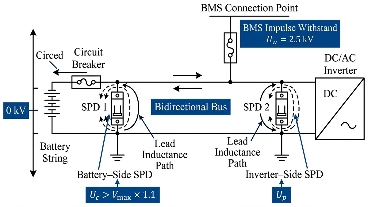
Transient protection becomes critical as soon as the ESS is exposed to switching surges, long cable runs, or grid-coupled inverter events. Surge protective devices in ESS applications face a condition that PV-only systems do not: the DC bus is bidirectional, with current reversing during charge and discharge.
IEC 61643-11 defines SPD performance for low-voltage DC systems and the protection level Up, the maximum voltage that appears at the device terminals during a surge. For ESS busbars operating at 800–1500 VDC, the selected SPD should have a Up at least 20% below the impulse withstand voltage of the connected inverter and BMS. In practice, where inverter withstand is 4 kV, a device with Up not exceeding about 2.5 kV preserves margin for lead inductance, which can add another 0.5–1.0 kV at the equipment terminals.
Placement generally follows a two-point rule: one SPD at the DC busbar entry point between the battery string and the inverter input, and a second at the AC/DC interface if the inverter is grid-tied. Omitting the busbar-side SPD leaves the battery controls exposed to lightning-induced and switching transients traveling along the DC cabling.
In a 12 MWh containerized ESS project in Fujian Province (2023), repeated BMS communication failures were traced to poor SPD selection. The installed devices had Up = 4.0 kV, exceeding the BMS impulse withstand rating of 2.5 kV. Replacing them with Type II SPDs rated Up ≤ 2.0 kV and adding a dedicated busbar-side mounting position eliminated the fault pattern over the following six months.
[Expert Insight]
– Keep SPD leads as short and straight as possible; excess lead length directly increases residual voltage at the protected equipment.
– Match Uc to the system’s real maximum charging voltage, not the nominal bus value printed on the single-line diagram.
– In coastal or thunderstorm-prone sites, inspect SPD status indicators during routine maintenance instead of waiting for an alarm from the inverter or BMS.
IEC 61643-11 also requires the SPD’s maximum continuous operating voltage (Uc) to exceed the system maximum DC voltage by at least 10%, helping prevent thermal overload during normal charging conditions.
After fault-clearing and surge control are defined, the system still needs a way to be made visibly safe for service work. A DC isolator is not a protective device; it is used to create a visible, verifiable open-circuit gap for maintenance and emergency shutdown.
The practical difference is breaking duty. A DC circuit breaker carries a rated short-circuit breaking capacity, often from 10 kA to 50 kA, allowing safe interruption of fault current. A DC switch-disconnector is normally rated for load-break duty under IEC 60947-3, not for fault interruption. If an isolator is opened under fault conditions, sustained arcing and contact damage are likely.
In a 12 MWh lithium-ion ESS project in Zhejiang Province (2023), maintenance crews found that a string-level disconnect had been substituted with an isolator rated AC-23A instead of the correct DC utilization category. During a routine shutdown, the device failed to clear a residual 8 A load at 800 VDC, welded shut, and forced full busbar de-energization.
IEC 60947-3 defines utilization categories that determine switching duty:
| 활용 범주 | 애플리케이션 | Typical Use in ESS |
|---|---|---|
| DC-20A | No-load switching only | Instrument isolation |
| DC-21A | Resistive loads, occasional switching | Battery string disconnect |
| DC-22A | Mixed resistive/inductive loads | Inverter input isolation |
| DC-23A | Highly inductive loads | Motor or transformer circuits |
For battery string isolation, DC-21A or DC-22A rated DC switch-disconnectors at 1000 VDC minimum are typical specifications. Voltage class is critical here: a device rated 500 VDC is not suitable on an 800 VDC bus.
IEC 60364-7-712 and NFPA 70E both require lockout/tagout capability on isolators used for maintenance access. A compliant device should provide a padlockable OFF handle, visible contact separation or a reliable OFF indicator, and finger-safe terminal shrouding. In ESS racks above 60 VDC, hazardous voltage thresholds make LOTO-capable isolation mandatory before any work on modules, busbars, or inverter DC terminals.
With all four devices specified, the real engineering challenge is making them operate in the right order under real site conditions. Effective ESS DC protection depends on how the fuse, breaker, SPD, and isolator behave as one coordinated stack without nuisance trips or cascading failures.
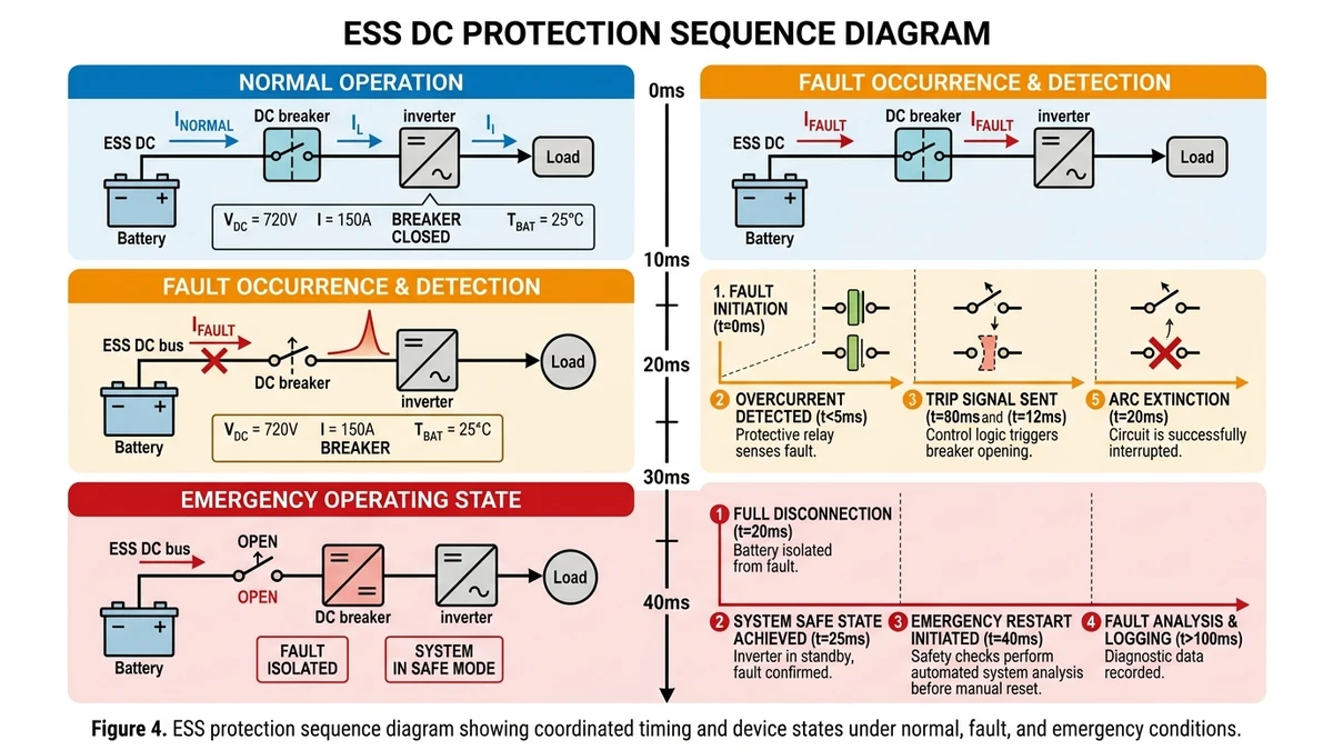
Under normal operation, the isolator remains closed, the SPD stays in standby, the breaker monitors current, and the fuse remains the final backup element. During a fault event, the breaker should trip first at its defined threshold before the fuse reaches its melting I²t. If the breaker fails to clear, the fuse interrupts as backup within its breaking capacity. The SPD should not conduct under sustained overcurrent; if it does, it will overheat and can create a secondary fault path.
In an emergency shutdown or fire suppression event, the isolator opens only after upstream breakers have cleared load current, because a DC switch disconnector is intended for isolation rather than fault interruption.
Ambient temperature, altitude, and installation layout all reduce effective ratings. Apply these derating factors before finalizing the stack:
In a 2 MWh lithium-ion ESS installation in Shandong Province (2023), a coordination mismatch caused string-level fuses to blow before rack breakers tripped during a cell-level short. The root cause was a fuse I²t lower than the breaker clearing profile at 800 VDC. After selecting DC MCBs with a lower instantaneous trip threshold and replacing the fuses with higher pre-arcing I²t ratings, the stack achieved proper selectivity: the breaker cleared first and the fuse remained intact as backup.
Specification quality determines whether the protection stack works in the field or only looks correct on paper. Selecting the right ESS DC protection stack requires matching five site parameters to device ratings: voltage class, fault current, response behavior, environmental exposure, and maintenance requirements.
Confirm system voltage class. ESS bus voltages commonly range from 48 VDC in residential systems to 400–800 VDC in commercial racks and up to 1500 VDC in utility-scale projects. Every device in the stack — fuse, breaker, SPD, and isolator — must be rated for the maximum DC voltage present.
Verify prospective short-circuit current. For a 500 kWh ESS rack at 800 VDC, the busbar PSCC commonly reaches 20–30 kA. Your DC MCCB should meet or exceed that Icu requirement under IEC 60947-2.
Match SPD protection level to equipment impulse withstand. Battery management systems often require clamping below about 2.5 kV, so select a DC surge protection device with a suitable Up value.
Confirm bidirectional fault current capability. ESS systems both charge and discharge, so fault current can flow in either direction. Components specified for one-way PV duty are not automatically suitable.
Verify isolator load-break rating and maintenance features. A DC switch disconnector should be selected by DC utilization category, voltage rating, and LOTO capability rather than by appearance or AC duty class.
For broader standards context, the IEC’s publicly available IEC homepage addresses safety requirements and standards access for grid-integrated ESS electrical systems.
A typical stack includes a fuse, a DC circuit breaker, an SPD, and a DC isolator, with each one covering a different electrical risk.
A breaker is resettable and selective, but it may not limit let-through energy as quickly as a properly coordinated fuse during severe short-circuit events.
Select a fuse with a DC rating above the system’s highest operating voltage, with practical design margin rather than matching nominal bus voltage exactly.
They are usually placed at the DC bus entry and, in grid-connected systems, near the inverter interface so transients are clamped before reaching sensitive electronics.
No. An isolator is intended for switching under no-load or rated load-break conditions depending on category, not for clearing short-circuit faults.
Icu is the maximum fault current a breaker can interrupt, while Ics indicates how much of that duty it can clear and still remain usable afterward.
Higher enclosure temperature reduces current-carrying capacity and can shift protection behavior, so derating must be applied during device selection.


