주소
304 북쪽 추기경
세인트 도체스터 센터, MA 02124
근무 시간
월요일~금요일: 오전 7시~오후 7시
주말: 주말: 오전 10시 - 오후 5시
주소
304 북쪽 추기경
세인트 도체스터 센터, MA 02124
근무 시간
월요일~금요일: 오전 7시~오후 7시
주말: 주말: 오전 10시 - 오후 5시

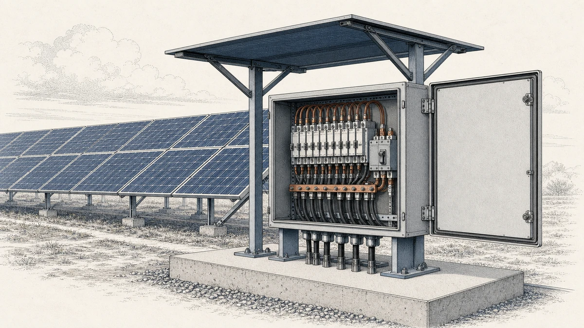
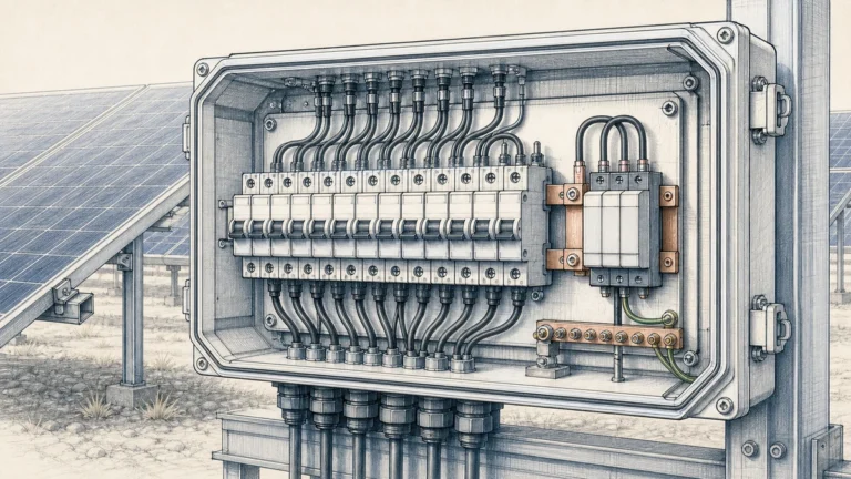
PV combiner box busbar temperature rise is not just a copper-size calculation. In a PV Combiner Box, the busbar operates inside an enclosure exposed to continuous DC current, high outdoor ambient temperature, solar radiation, cable heat, protective-device losses, and limited airflow. For Sinobreaker PV Combiner Box projects, busbar sizing should therefore be verified as part of the complete assembly, not treated as an isolated conductor selection.
IEC 61439-1:2020 is the key reference for low-voltage switchgear and controlgear assemblies. It covers definitions, service conditions, construction requirements, technical characteristics, and verification requirements, and its 2020 edition refocused temperature-rise verification on group rated current while adding DC-related requirements. That matters for PV combiner boxes because multiple string inputs can operate together for long periods, and the output busbar may carry sustained DC current under severe environmental conditions.
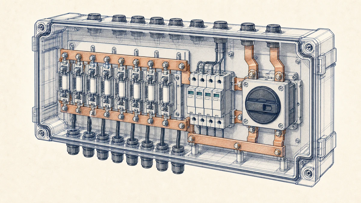
A busbar that appears adequate by cross-section may still run too hot when installed in a sealed or semi-sealed outdoor enclosure. Excess temperature rise can reduce insulation life, accelerate oxidation at bolted joints, increase contact resistance, and transfer heat to fuses, disconnect switches, surge protection devices, terminals, and cable insulation.
The busbar temperature depends on more than copper or aluminum area. Important factors include:
This is why a manufacturer busbar example showing the relationship between current loading, ambient conditions, and conductor temperature is useful: current-carrying conductors must be evaluated under stated installation conditions, not by cross-section alone.
In many AC distribution applications, peak current may be intermittent. A PV Combiner Box is different. During strong irradiance, the busbar may carry high DC current for hours. The heating effect is continuous, and the enclosure may already be hot from direct sun exposure.
For Sinobreaker PV Combiner Box design, this means the busbar should be considered under realistic maximum operating scenarios: high irradiance, elevated ambient temperature, all active strings contributing current, and enclosure heat accumulation.
The busbar is one heat source, but it is also surrounded by other components that contribute to the final internal temperature. Verification should look at the complete thermal environment.
Busbar heating is mainly caused by resistive loss:
“text“
P = I²R
Where:
P is power loss in wattsI is current in amperesR is electrical resistance in ohmsAs current increases, heat rises with the square of current. A modest current increase can create a much larger heat increase, especially at joints where contact resistance is higher than the straight conductor resistance.
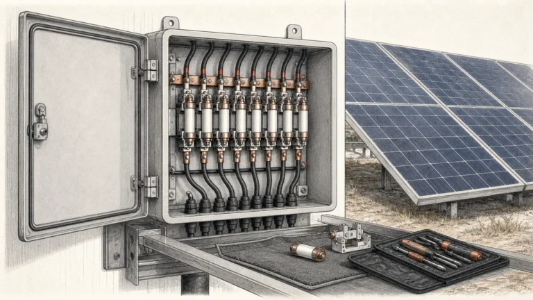
Bolted joints, fuse holder interfaces, cable lugs, and switch terminals can become local hot spots. Even if the busbar body is acceptable, a poorly designed or poorly tightened connection can exceed safe temperature limits.
For PV combiner boxes, joint design should consider:
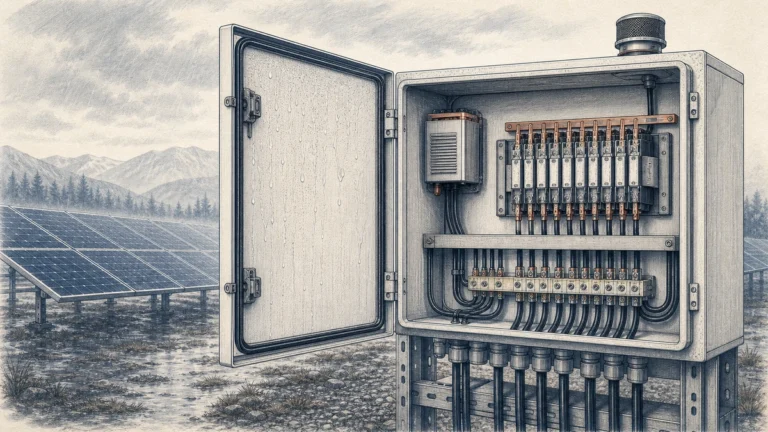
Outdoor PV combiner boxes are often installed where shading is limited. Direct solar radiation raises enclosure surface temperature, and the internal air temperature may exceed the surrounding ambient temperature. For exposed PV installations, direct solar heat and enclosure airflow affect internal temperature; practical measures such as a sun cover and an air gap can help reduce enclosure temperature and maintain circulation.
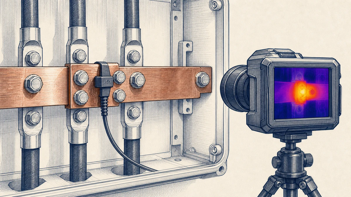
Busbar sizing should start from electrical rating, then be checked against thermal, mechanical, and installation requirements. The goal is not only to select a conductor that carries current, but to confirm that the complete PV Combiner Box remains within acceptable temperature limits.
Start by determining the maximum continuous current expected at the combiner output. For a PV Combiner Box, this normally depends on:
The busbar should be rated for the combined operating current, not only a nominal nameplate value. If all input circuits can operate simultaneously, the thermal design should reflect that condition.
IEC 61439-1:2020 places emphasis on temperature-rise verification linked to group rated current. In practice, this means the assembly should be assessed based on the current that a group of circuits can carry at the same time under defined conditions.
For a PV Combiner Box, group rated current is especially relevant because several string circuits feed the same busbar and output circuit. The verification should consider the combined load path: input terminals, fuses or breakers, positive and negative busbars, disconnecting device, output terminals, and internal conductors.
Copper is commonly used because of its high conductivity and stable performance in compact assemblies. Aluminum may be used in some applications, but it requires careful attention to larger cross-section, surface treatment, connection compatibility, and torque stability.
Key busbar parameters include:
A larger cross-section lowers resistance, but it does not automatically solve every temperature-rise issue. If the enclosure is hot, airflow is poor, or connections are inadequate, the busbar may still exceed the intended limit.
The same busbar can have different operating temperatures in different installations. A busbar mounted in free air, a ventilated cabinet, and a sealed outdoor PV box will not behave the same way.
Design assumptions should state:
For Sinobreaker PV Combiner Box applications, the busbar rating should be matched with the actual enclosure and installation environment.
Temperature-rise verification is the process of confirming that the assembly remains within defined thermal limits under specified loading and service conditions. It may involve testing, calculation, comparison with a verified design, or a combination depending on the applicable standard and project requirements.
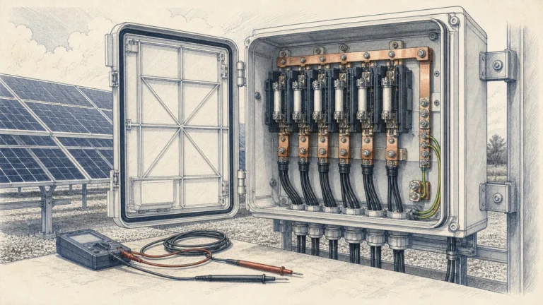
Testing is the most direct method. A representative PV Combiner Box is loaded at the specified current until thermal stability is reached. Temperature is then measured at critical points.
Typical measurement points include:
Thermal stability should be reached before final readings are recorded. The test setup should document current, ambient temperature, enclosure configuration, cable size, cable entry arrangement, ventilation state, and mounting position.
Calculation can be used during design development to estimate busbar losses and likely temperature rise. It is useful for comparing alternatives, such as wider busbars, shorter current paths, improved joint design, or better internal spacing.
However, calculation should be treated carefully because enclosure effects are complex. Solar gain, restricted airflow, nearby heat sources, and contact resistance can significantly change actual temperature. Calculation is strongest when supported by measured data from similar verified Sinobreaker PV Combiner Box designs.
If a new PV Combiner Box design is closely related to an already verified design, comparison may be appropriate. The comparison should confirm that the new design is not thermally more severe.
Check whether the new design has:
If the new design has higher current, smaller enclosure volume, more devices, reduced spacing, or harsher sunlight exposure, additional verification is usually needed.
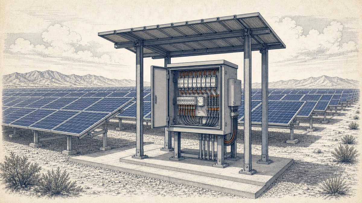
Reducing busbar temperature is not only about increasing metal size. Often, better thermal performance comes from improving the full current path and enclosure environment.
A short, direct current path reduces resistance and heat. Avoid unnecessary bends, narrow transitions, and long busbar runs. Use symmetrical layouts where practical so current distribution is even across parallel paths.
Recommended controls include:
Even sealed outdoor enclosures have internal air movement caused by heat gradients. Layout can either help or restrict this movement. Avoid packing large devices tightly around the busbar if they block heat dissipation.
Design options may include:
For exposed PV installations, the enclosure may absorb significant solar heat. A sun cover with an air gap can reduce direct enclosure heating and help maintain air circulation around the box. This is especially important where the combiner box is mounted in open fields, on rooftops, or near reflective surfaces.
For Sinobreaker PV Combiner Box projects, solar-heating control should be discussed early because it may affect enclosure size, bracket design, mounting clearance, and maintenance access.
A good verification record helps engineers, installers, and inspectors understand what was proven and under which conditions. It also helps avoid misuse of the PV Combiner Box outside its verified rating.
The verification file should identify:
The record should clearly state whether the results apply only to the tested configuration or also to defined variants.
A practical review should ask:
If any answer is uncertain, the design should be revised or reverified before release.
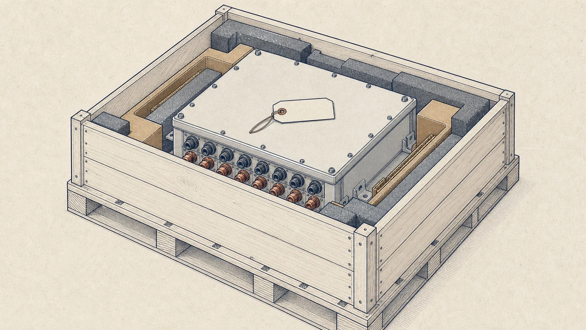
PV combiner box busbar temperature rise problems often come from assumptions that seem reasonable but are incomplete.
A busbar table may give a current value, but that value depends on conditions such as ambient temperature, conductor orientation, enclosure type, and ventilation. A busbar that performs well in open air may run too hot inside a compact outdoor enclosure.
Ambient temperature alone may not represent the internal temperature of an enclosure under direct sunlight. Solar gain can push the internal air temperature much higher than expected, increasing the operating temperature of the busbar and nearby devices.
Many thermal failures begin at joints, not in the middle of a busbar. Loose bolts, insufficient contact area, incompatible metals, or oxidation can create localized hot spots that are not predicted by simple conductor calculations.
A verified design should not be stretched too far. Changing the enclosure size, device arrangement, cable entry, busbar spacing, or current rating can change the thermal behavior. Each significant design change should be reviewed for its effect on temperature rise.
For Sinobreaker PV Combiner Box solutions, busbar temperature-rise control should be built into the design process from the beginning. The most reliable approach combines conservative current-path sizing, good enclosure thermal design, controlled production processes, and verification aligned with IEC 61439-1:2020 principles.
The key point is simple: pv combiner box busbar temperature rise must be verified under the conditions in which the assembly will actually operate. Rated current, group loading, solar exposure, enclosure airflow, and joint quality all influence the final result.
A well-designed PV Combiner Box should provide:
Excessive temperature rise is usually caused by high continuous DC current, insufficient busbar cross-section, poor joint contact, limited enclosure airflow, high ambient temperature, direct solar heating, or nearby heat-generating components. In many cases, several of these factors occur together.
Not always. A larger busbar can reduce conductor losses, but it cannot fully correct poor ventilation, excessive solar heating, bad connections, undersized terminals, or compact layouts with multiple heat sources. The complete PV Combiner Box assembly should be checked.
It should be verified under defined service conditions using testing, calculation, or comparison with a verified design, as appropriate for the project and applicable standards. For the most reliable result, the verification should consider group rated current, actual enclosure configuration, ambient temperature, cable terminations, and solar-exposed installation conditions.