주소
304 북쪽 추기경
세인트 도체스터 센터, MA 02124
근무 시간
월요일~금요일: 오전 7시~오후 7시
주말: 주말: 오전 10시 - 오후 5시
주소
304 북쪽 추기경
세인트 도체스터 센터, MA 02124
근무 시간
월요일~금요일: 오전 7시~오후 7시
주말: 주말: 오전 10시 - 오후 5시

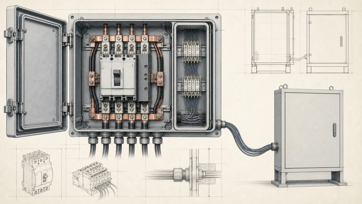
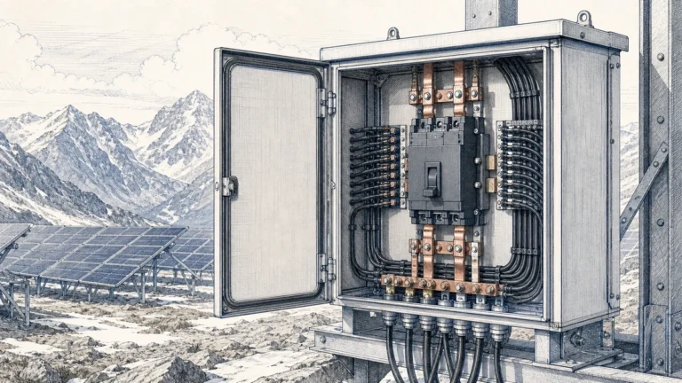
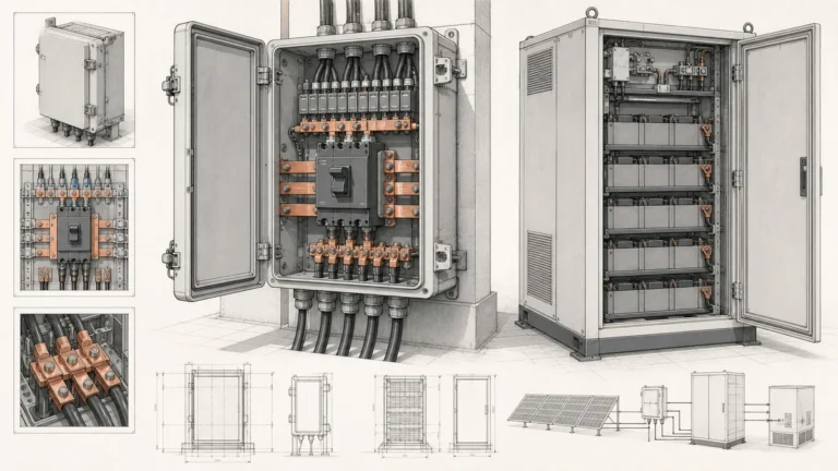
DC circuit breaker auxiliary contacts are small signal contacts used to report the mechanical position of a DC breaker to a remote device, such as a combiner box monitor, PLC, BMS, EMS, or SCADA system. In photovoltaic combiner panels and energy storage system panels, these signals help operators confirm whether a breaker is open, closed, tripped, or unavailable for operation.
For Sinobreaker DC Circuit Breaker applications, auxiliary contacts are especially useful where the breaker is installed inside an enclosure and the operator needs reliable remote status feedback without opening the panel door.
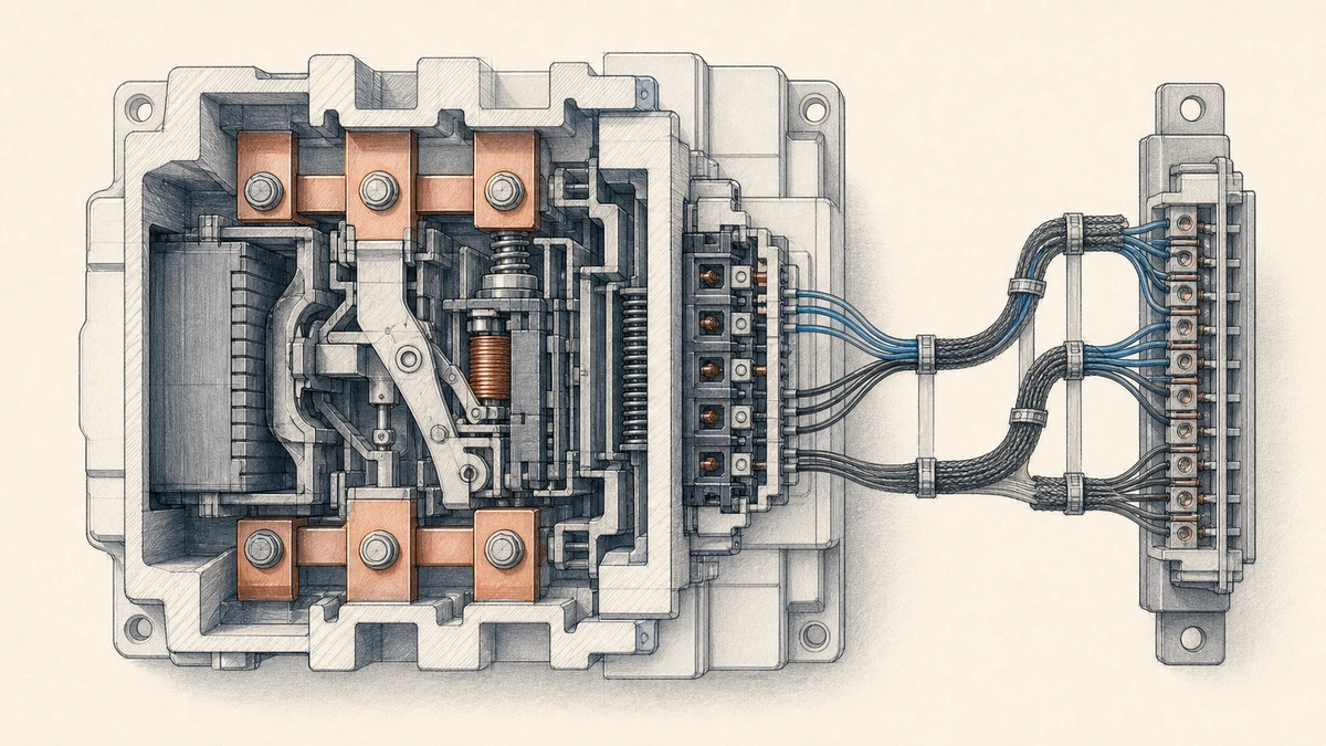
In DC power systems, visual inspection is not always practical. A combiner box may be installed outdoors, an ESS cabinet may be locked, and a DC distribution panel may be monitored from a control room. Auxiliary contacts provide a low-power status signal that helps the operator understand the breaker state from a safe distance.
A properly wired auxiliary contact can support:
The key point is that auxiliary contacts do not interrupt the main DC load current. They only follow the position of the breaker mechanism and send a separate control signal to the monitoring circuit.
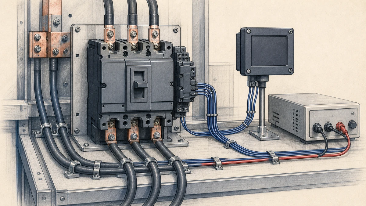
DC circuit breaker auxiliary contacts are mechanically linked to the breaker operating mechanism. When the main breaker contacts change position, the auxiliary contact changes state as well.
A typical configuration may include:
NO contact: normally open, closes when the breaker is ONNC contact: normally closed, opens when the breaker is ONFor example, when a Sinobreaker DC Circuit Breaker is switched ON, the auxiliary contact may close a low-voltage signal loop to indicate “breaker closed” to a PLC input. When the breaker is switched OFF, the signal changes and the control system displays “breaker open.”
The main contacts carry the DC power circuit. The auxiliary contacts carry only the indication circuit.
This distinction matters because the auxiliary contact is a reporting device, not a protection device. It tells the control system what the breaker mechanism is doing, but it does not replace proper voltage testing, isolation procedures, or lockout/tagout practices.
Incorrect indication can create serious operational risk. If a remote system shows a breaker as open when it is actually closed, personnel may make unsafe assumptions. For this reason, auxiliary contact operation should be checked during commissioning and included in periodic functional testing.
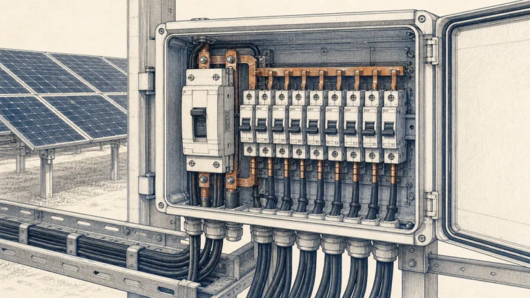
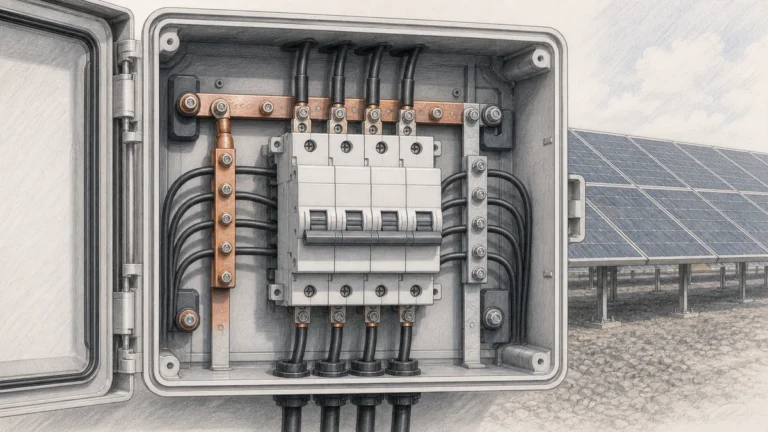
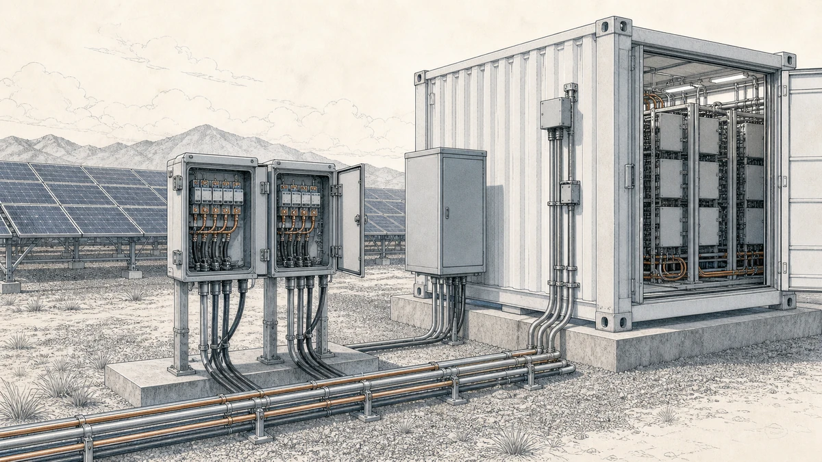
PV combiner boxes often contain multiple DC strings, fuses, surge protection devices, and DC circuit breakers. When a breaker opens, the operator may need to know whether a string group or array section has been disconnected.
In this setting, dc circuit breaker auxiliary contacts can help provide:
A common signal path is:
“text“
Sinobreaker DC Circuit Breaker
↓
Auxiliary Contact
↓
Combiner Monitoring Module / PLC Input
↓
Plant SCADA or Remote Operator Interface
This arrangement allows the operator to see whether the DC breaker has been manually opened, closed after maintenance, or left in an unexpected position.
Even though auxiliary contacts are used for low-power signals, their voltage and current ratings must match the control circuit. The main breaker may be rated for high-voltage DC power, while the auxiliary contact may be rated for a separate AC or DC control voltage.
Before installation, confirm:
Using the auxiliary contact outside its rated signal capacity can cause contact wear, unreliable indication, or failure of the remote status circuit.
Energy storage systems rely heavily on remote monitoring. Battery racks, DC combiner panels, PCS input cabinets, and DC distribution enclosures may all need clear breaker status indication.
In ESS panels, dc circuit breaker auxiliary contacts can provide feedback to:
A BMS or EMS may need to know whether a DC breaker is closed before allowing charge or discharge. Auxiliary contacts can provide this position signal.
For example:
“text“
Breaker closed → BMS receives closed-status input → System permits operation
Breaker open → BMS receives open-status input → System blocks operation or reports alarm
This helps coordinate the DC protection system with software-based energy control logic. However, auxiliary contacts should not be treated as the only safety confirmation. In critical maintenance conditions, technicians must verify the actual electrical state according to site procedures.
Auxiliary contacts and alarm contacts are often confused, but they serve different purposes.
An auxiliary contact usually indicates the open or closed position of the breaker. It follows the main contact position.
An alarm contact, trip contact, or signal contact may indicate that the breaker opened because of a protection event. This can help distinguish a normal manual opening from a fault-related trip.
Open/close indication answers the question:
“text“
Is the breaker currently ON or OFF?
This is the most common role of an auxiliary contact. It is useful for remote status display, interlocks, and basic monitoring.
Trip or fault indication answers a different question:
“text“
Did the breaker open because of a protection trip?
This distinction is important in PV and ESS systems. A breaker that is manually switched OFF may require a different response than a breaker that trips due to overcurrent or another protective condition. Where trip indication is needed, choose the proper breaker accessory combination rather than relying only on a standard auxiliary contact.
Auxiliary contact wiring should be planned as part of the control system, not treated as an afterthought. The signal may be simple, but it can affect operator decisions and automated logic.
Decide whether the monitoring system should use a normally open or normally closed signal.
A normally open circuit may be easy to understand because the input turns ON when the breaker closes. A normally closed circuit may be preferred in some monitoring designs because a broken wire can be detected as a loss of signal.
The best choice depends on the control philosophy, alarm logic, and system safety requirements.
Keep auxiliary contact signal wiring separated from high-current DC conductors as much as practical. This helps reduce electrical noise and improves serviceability inside the panel.
Good practice includes:
Before connecting auxiliary contacts to a PLC, BMS, or monitoring device, confirm the input type.
Check whether the monitoring input expects:
A dry contact is simply an isolated contact that opens or closes a circuit supplied by another device. Many remote indication systems use this method because it keeps the breaker accessory electrically separate from the monitoring power source.
Commissioning should verify that the remote signal matches the actual breaker state. This is especially important because an incorrect indication can lead to wrong operation decisions.
A basic functional test may include:
1. Confirm the breaker is safely installed and wired.
2. Switch the breaker to ON and verify the remote closed indication.
3. Switch the breaker to OFF and verify the remote open indication.
4. If a trip contact is installed, verify the trip signal according to the test procedure.
5. Record the result in the panel commissioning documentation.
Auxiliary contacts are mechanical signal devices, so they should be tested periodically. Dust, vibration, terminal loosening, contact wear, wiring damage, or incorrect maintenance can affect the signal path.
For PV and ESS panels, periodic checks are especially useful after:
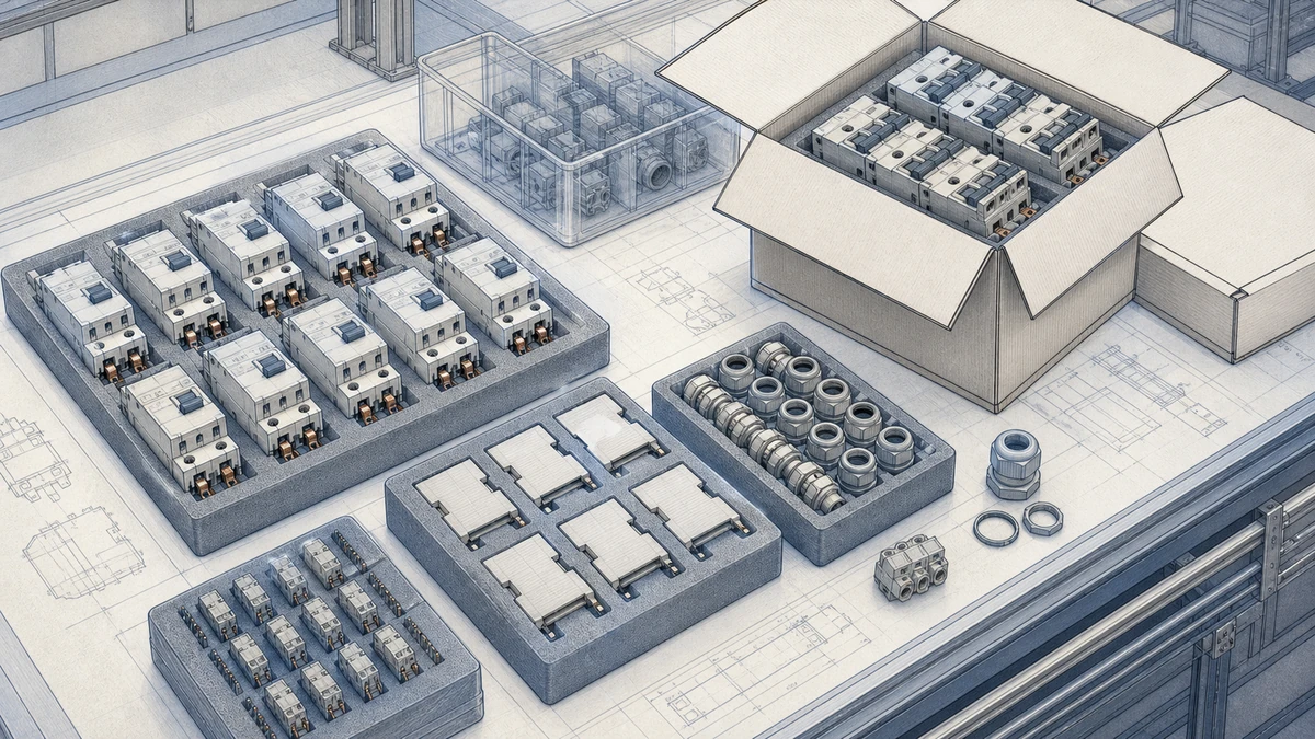
When specifying auxiliary contacts for a Sinobreaker DC Circuit Breaker, consider both the breaker and the monitoring system.
Important selection points include:
A PV combiner panel may only need simple ON/OFF indication for each outgoing DC breaker. An ESS panel may require more detailed status logic, including breaker closed, breaker open, and fault trip signals.
For this reason, the accessory choice should be based on the system control requirement, not only on the breaker rating.
Avoid these common issues when applying dc circuit breaker auxiliary contacts:
The most reliable designs combine correct accessory selection, clear wiring diagrams, proper testing, and routine inspection.
DC circuit breaker auxiliary contacts are used to send remote ON/OFF status signals from a DC breaker to a monitoring or control system. They help operators confirm breaker position in PV combiner boxes, ESS panels, DC distribution cabinets, and other DC power equipment.
Standard auxiliary contacts usually show open or closed position. To identify whether the breaker opened because of a protection trip, a separate alarm contact, trip contact, or signal contact may be required. The correct accessory depends on the breaker model and the monitoring requirement.
Auxiliary contacts should be tested during commissioning and checked periodically as part of panel maintenance. They should also be verified after wiring changes, accessory replacement, abnormal shutdowns, or any event where remote indication accuracy is important.