주소
304 북쪽 추기경
세인트 도체스터 센터, MA 02124
근무 시간
월요일~금요일: 오전 7시~오후 7시
주말: 주말: 오전 10시 - 오후 5시
주소
304 북쪽 추기경
세인트 도체스터 센터, MA 02124
근무 시간
월요일~금요일: 오전 7시~오후 7시
주말: 주말: 오전 10시 - 오후 5시


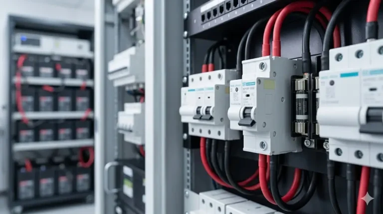
Installing DC miniature circuit breakers correctly is critical for safe, reliable solar PV system operation. Unlike plug-and-play AC installations, DC MCB installation requires attention to voltage ratings, polarity considerations, thermal management, and specialized DC interruption requirements.
This practical guide walks professional installers through every step of DC miniature circuit breaker installation—from initial planning and wire sizing to final testing and commissioning. Whether you’re installing string-level protection in a solar combiner box or main array protection feeding an inverter, these proven techniques ensure code-compliant, safe installations.
We’ll cover the complete installation workflow: tools and materials, DIN rail preparation, mounting procedures, wiring techniques with proper torque specifications, testing protocols, and common installation mistakes that lead to failures. This is the field-tested knowledge installers need for first-time-right DC MCB installations.
🎯 Installer Focus: This guide emphasizes practical field techniques, not theoretical engineering. We assume you have basic electrical knowledge and focus on the specific challenges of DC miniature circuit breaker installations.
Before opening your toolbox, gather and verify critical system parameters:
Solar PV Array Data:
– Number of strings in parallel
– Module Isc (short-circuit current) from datasheet
– Module Voc (open-circuit voltage) at coldest expected temperature
– String configuration (series modules per string)
– Total array Voc and Isc
Example Documentation:
Array: 8 strings × 20 modules per string
Module: 400W, Isc = 11.2A, Voc = 48.5V (STC)
String Voc: 20 × 48.5V = 970V (STC)
String Voc at -10°C: 20 × 54.8V = 1,096V (temp coefficient applied)
String Isc: 11.2A
Combined Isc: 8 × 11.2A = 89.6A
Inverter Requirements:
– Maximum input voltage
– Maximum input current
– Required breaking capacity (from manual or nameplate)
For String-Level MCBs (NEC 690.8):
I_MCB = I_sc × 1.56
V_MCB ≥ String V_oc (at coldest temp) × 1.2 safety margin
예:
– Module Isc: 11.2A
– Required current: 11.2A × 1.56 = 17.5A
– Select: 20A DC MCB (next standard size)
– String Voc: 1,096V (at -10°C)
– Required voltage: 1,096V × 1.2 = 1,315V
– Select: 1500V DC MCB (next standard rating)
For Main Array MCB:
I_MCB = (N_strings × I_sc × 1.25) ÷ 0.8
예:
– 8 strings × 11.2A × 1.25 = 112A
– 112A ÷ 0.8 = 140A
– Select: 160A or 200A DC MCB
⚠️ 중요: Always round UP to the next standard MCB size. Never round down—this violates NEC and creates fire hazards.
The DC miniature circuit breaker protects the WIRE, not the solar panels. Wire ampacity must support the MCB rating after temperature derating.
Temperature Derating Formula:
I_wire_derated = I_ampacity_30C × f_temp
NEC Table 310.15(B)(2)(a) Common Factors:
– 40°C ambient: f = 0.91
– 50°C ambient: f = 0.82
– 60°C ambient: f = 0.58
– 70°C ambient: f = 0.41
예:
– MCB selected: 20A
– Wire: 10 AWG (30A ampacity at 30°C per NEC Table 310.16)
– Installation: Roof-mounted conduit (60°C expected)
– Derated ampacity: 30A × 0.58 = 17.4A
- 문제: 20A MCB exceeds 17.4A wire capacity
- 솔루션: Upsize to 8 AWG (40A × 0.58 = 23.2A) ✓
Plan physical MCB arrangement before installation:
Heat Dissipation Requirements:
– Maintain 10mm (0.4″) minimum spacing between MCBs
– Group high-current MCBs (>63A) with extra spacing
– Ensure 100mm (4″) clearance above and below for air circulation
– Avoid placing MCBs directly above heat-generating components
Accessibility Requirements:
– All MCB toggles must be accessible without tools
– Mounting height: 1.2-1.8m (4-6 feet) from working surface
– Labels must be readable from normal working distance
– Emergency disconnect MCBs at eye level
Labeling Plan:
Create labeling scheme before installation:
String 1 MCB: "PV STRING 1 - 20A - 1500V DC"
String 2 MCB: "PV STRING 2 - 20A - 1500V DC"
Main MCB: "PV MAIN DISCONNECT - 160A - 1500V DC"
Hand Tools:
– Torque screwdriver set (0.5-4.0 Nm range) with audible click
– Wire strippers (10-22 AWG range)
– Multimeter with DC voltage/current capability
– DIN rail cutter or hacksaw
– Side cutters/diagonal pliers
– Ferrule crimper (for stranded wire)
– Label maker or pre-printed labels
– Scratch awl or marking pen
Power Tools:
– Cordless drill with appropriate bits
– Impact driver (for panel mounting)
– Knockout punch set or step bit
Safety Equipment:
– Insulated gloves rated for system voltage
– Safety glasses
– Arc flash PPE (if working on energized equipment)
– Voltage detector/tester
Primary Components:
– DC miniature circuit breakers (proper ratings verified)
– 35mm DIN rail (cut to length)
– DIN rail end stops
– Wire ferrules (matching wire gauge)
– Wire markers or labels
– Cable ties and mounting accessories
Optional but Recommended:
– Busbar system (for multiple MCB connections)
– Terminal blocks for neutral/ground
– Surge protection devices (SPDs)
– Ventilation fans (for enclosed combiner boxes)
🎯 전문가 팁: Invest in a quality torque screwdriver (Wera, Wiha, or similar). Over-tightened terminals cause 40% of MCB failures. Under-tightened terminals cause another 30%. Proper torque eliminates both issues.

Step 1.1: Cut DIN Rail to Length
Measure and cut 35mm DIN rail to fit enclosure:
1. Measure internal panel width
2. Subtract 20mm (10mm each end for clearance)
3. Mark rail with scratch awl
4. Cut with DIN rail cutter or hacksaw
5. Deburr cut edges with file
6. Clean rail with cloth to remove metal shavings
Step 1.2: Mount DIN Rail
Secure rail to panel back plate:
1. Position rail horizontally (verify with level)
2. Mark mounting hole locations (every 150-200mm)
3. Drill holes appropriate for mounting surface
4. Install mounting screws (M5 or #10 typical)
5. Torque screws to manufacturer specification
6. Verify rail doesn’t flex when pressed
Step 1.3: Install End Stops
Prevent MCB lateral movement:
1. Slide end stops onto rail ends
2. Tighten set screws (hand-tight, then 1/4 turn)
3. Verify MCBs cannot slide off rail ends
Step 2.1: MCB Orientation Check
Before mounting, verify:
– MCB toggle faces outward (accessible)
– “ON” position is upward (standard orientation)
– Input terminals at top, output terminals at bottom
– Voltage and current ratings visible after installation
Step 2.2: Snap MCB onto DIN Rail
Proper mounting technique:
1. Tilt MCB backward at 30° angle
2. Hook top rear clip onto top edge of DIN rail
3. Press bottom of MCB forward until you hear/feel click
4. MCB should be firmly seated—no wobble
5. Verify MCB cannot be pulled off without releasing latch
Step 2.3: Position Multiple MCBs
For combiner box with multiple MCBs:
1. Start from one end (left or right, your preference)
2. Install MCBs in order of circuit numbers
3. Maintain 10mm minimum spacing (one module width)
4. Group related circuits together (all strings, then main MCB)
5. Leave space for future expansion if applicable
Step 2.4: Verify Mechanical Installation
Perform these checks before wiring:
– All MCBs firmly seated on rail ✓
– No visible gaps between MCB and rail ✓
– Toggles move freely through full range ✓
– Adequate spacing for heat dissipation ✓
– Terminal screws accessible ✓

Step 3.1: Wire Cutting and Stripping
Precise wire preparation prevents connection issues:
Wire Length Calculation:
– Measure from MCB terminal to cable entry point
– Add 150mm (6″) service loop inside panel
– Add 50mm (2″) for terminal connection
– Cut wire to total calculated length
Stripping Technique:
1. Check MCB terminal marking for strip length (typically 10-12mm)
2. Adjust wire stripper to correct AWG setting
3. Strip insulation cleanly—no nicked conductors
4. Inspect: all copper strands intact, no partial cuts
5. If using stranded wire, proceed to ferrule installation
Step 3.2: Ferrule Installation (Stranded Wire)
Ferrules prevent strand breakage and improve connection:
1. Select ferrule matching wire gauge (color-coded)
2. Slide ferrule onto stripped wire end
3. Insert fully into crimper die (correct size)
4. Crimp firmly—single compression stroke
5. Inspect: ferrule should not slide off wire
6. Measure exposed conductor: should match MCB spec (10-12mm)
Step 3.3: Terminal Connection Sequence
CRITICAL SAFETY: Verify system is de-energized before connecting wires:
– Open all PV disconnect switches
– Cover solar panels with opaque material OR work at night
– Verify 0V with multimeter
Connection Order:
Always connect in this sequence to avoid energizing disconnected circuits:
1. Load side first (bottom terminals—going to inverter/loads)
2. Source side last (top terminals—coming from PV array)
This ensures if a wire accidentally contacts ground during installation, the MCB can trip to protect you.
Wiring Technique:
1. Loosen terminal screw completely (3-4 full turns)
2. Insert wire/ferrule fully into terminal
– Wire should bottom out in terminal chamber
– No copper visible outside terminal
– Insulation should not enter terminal
3. Begin tightening screw by hand
4. Switch to torque screwdriver
Step 3.4: Torque Specifications
Critical Torque Values by MCB Size:
| MCB Rating | Torque Spec | 전선 크기 범위 |
|---|---|---|
| 6-16A | 2.0 Nm (17.7 in-lb) | 14-10 AWG |
| 20-32A | 2.5 Nm (22.1 in-lb) | 12-8 AWG |
| 40-63A | 3.0 Nm (26.6 in-lb) | 10-6 AWG |
| 80-125A | 3.5 Nm (31.0 in-lb) | 8-2 AWG |
Torquing Procedure:
1. Set torque screwdriver to specified value
2. Place bit fully in terminal screw head
3. Apply steady, even pressure
4. Turn until you hear/feel click
5. Stop immediately—do not overtighten
6. Visually verify screw head is flush with MCB housing
⚠️ 경고: Over-torquing cracks terminal housings and damages internal connections. Under-torquing allows terminals to loosen over time from thermal cycling, leading to arcing and fire. ALWAYS use a torque screwdriver—never “feel” or guess.
Step 3.5: Pull Test Verification
After torquing each terminal:
1. Grasp wire 100mm (4″) from terminal
2. Pull firmly with ~50N force (11 lbs)
3. Wire should NOT move or pull out
4. If wire moves, remove and reconnect
For multiple MCBs sharing common input, busbars simplify wiring:
Pin-Type Busbar Installation:
1. Verify busbar voltage and current ratings
2. Insert busbar pins into top terminals of all MCBs
3. Tighten each terminal to specified torque
4. Connect single supply wire to busbar feed terminal
5. Torque busbar feed terminal
Comb-Style Busbar Installation:
1. Remove terminal screws from all MCBs
2. Slide comb busbar into terminals
3. Reinstall and torque all terminal screws
4. Connect supply wires to busbar taps
Advantages of Busbars:
– Reduces wiring complexity by 60%
– Eliminates wire-to-wire connections
– Lowers contact resistance
– Cleaner, more professional appearance
– Easier troubleshooting and future modifications

Test 1: Visual Inspection
Complete walk-through inspection:
– [ ] All MCBs firmly mounted on DIN rail
– [ ] All terminal screws torqued (no loose connections)
– [ ] No copper conductor visible outside terminals
– [ ] Wire insulation in good condition (no damage)
– [ ] Adequate wire support (no mechanical stress on terminals)
– [ ] All labels installed and legible
– [ ] Panel interior clean (no wire scraps, tools, debris)
– [ ] Ventilation openings clear
Test 2: Continuity Check
With system de-energized and PV array covered:
1. Set multimeter to continuity/resistance mode
2. Close MCB (toggle to ON position)
3. Measure resistance across MCB input to output
4. Reading should be <1Ω (typically 0.1-0.5Ω) 5. Open MCB (toggle to OFF position) 6. Measure resistance again 7. Reading should be >10MΩ (open circuit)
8. Repeat for all poles of all MCBs
Test 3: Insulation Resistance (Megger Test)
Verify no insulation breakdown:
1. Set megger to appropriate DC voltage (typically 500V or 1000V)
2. Disconnect all loads and sources from MCB
3. Close MCB
4. Test between line and ground
5. Test between load and ground
6. Test between line and load (MCB open)
7. All readings should exceed 1MΩ minimum (prefer >10MΩ)
⚠️ Failure Indication: If insulation resistance <1MΩ, you have a ground fault. Check for: damaged wire insulation, moisture in enclosure, incorrect wiring, or damaged MCB.
Test 4: Initial Voltage Measurement
Uncover PV array or wait for daylight:
1. Keep all MCBs in OFF position
2. Measure voltage at MCB input terminals (from PV)
3. Verify voltage matches calculated Voc ±10%
4. Measure each string individually if accessible
5. Look for significant voltage imbalances (>5% variation suggests fault)
예:
Expected String Voc: 980V (at current temperature)
Measured Values:
- String 1: 975V ✓
- String 2: 982V ✓
- String 3: 760V ✗ (Problem—likely shading or module fault)
- String 4: 978V ✓
Test 5: Controlled Energization
Bring system online safely:
1. Start with all MCBs OFF
2. Close main array MCB first
3. Measure voltage at inverter input—should match array Voc
4. Close individual string MCBs one at a time
5. Monitor inverter display for normal startup
6. Verify current flow with clamp meter or inverter display
7. Check for abnormal sounds (arcing, buzzing)
Test 6: Manual Trip Function Test
Verify mechanical operation:
1. With system energized under load
2. Manually trip each MCB to OFF position
3. Verify current stops flowing (check inverter display)
4. Reset MCB to ON position
5. Verify current resumes
6. Confirm smooth toggle action (not sticky or difficult)
Test 7: Load Test and Thermal Inspection
Monitor initial operation:
1. Allow system to operate for 30 minutes under load
2. Use infrared thermometer to measure MCB temperatures
3. MCB body temperature should be <60°C above ambient 4. All MCBs at similar temperature ±10°C 5. No hot spots at terminals (indicates loose connection)
Acceptable Thermal Profile:
– Ambient: 30°C
– MCB body: 45-55°C (15-25°C rise) ✓
– Terminal: 50-60°C (20-30°C rise) ✓
Problem Indicators:
– MCB body >70°C: Possible overload or inadequate ventilation
– Terminal >80°C: Loose connection—shut down and re-torque
– One MCB significantly hotter: Possible internal defect
Required Labels:
Each DC miniature circuit breaker must be labeled with:
1. Circuit identification: “PV STRING 1”, “PV MAIN DISCONNECT”
2. 정격 전압: “1500V DC”
3. 현재 등급: “20A”
4. Warning labels: “DC DISCONNECT – PV SYSTEM”
NEC 690.13 Labeling Requirements:
Permanent labels required at all disconnecting means:
WARNING
DC DISCONNECT
DO NOT OPEN UNDER LOAD
PV SYSTEM DC DISCONNECT MAX VOLTAGE: 1500V DC MAX CURRENT: 160A
Documentation Package:
Create and file these documents:
1. As-built panel schedule: List all MCBs with ratings and circuits
2. Installation photos: Panel interior before and after
3. Test results: Record all test measurements
4. Torque checklist: Sign-off that all terminals torqued
5. Wire schedule: Document wire gauges and routing

문제: Wiring MCB input terminals from the bottom and output terminals from the top—opposite of standard convention.
Why this happens: Installer doesn’t pay attention to “line” and “load” terminal markings.
결과:
– Confuses future technicians during troubleshooting
– May affect arc chute operation in some MCB designs
– Violates electrical code in some jurisdictions
예방:
– Always wire: SOURCE → top terminals, LOAD → bottom terminals
– Verify MCB markings before wiring (“1” or “L” = line/top, “2” or “T” = load/bottom)
– Follow consistent convention throughout entire installation
문제: Selecting correct MCB rating per NEC 690.8 (Isc × 1.56), but forgetting temperature derating for wire ampacity.
예:
– Module Isc: 11.2A
– MCB correctly sized: 11.2A × 1.56 = 17.5A → 20A MCB ✓
– Wire selected: 10 AWG (30A at 30°C) ✓
- Missed: Roof conduit at 60°C → 30A × 0.58 = 17.4A
- 결과: 20A MCB can pass current that overheats 17.4A wire
예방:
1. Calculate MCB rating from NEC 690.8
2. Verify wire ampacity at expected ambient temperature
3. Ensure wire ampacity ≥ MCB rating after derating
4. If wire insufficient, upsize wire (not downsize MCB)
문제: Using impact driver or over-applying torque, cracking MCB housing.
Why this happens: Installer accustomed to torquing large lugs or doesn’t own torque screwdriver.
결과:
– Cracked terminal housing (may not be immediately visible)
– Internal connection damage
– MCB failure after weeks/months when crack propagates
– Moisture ingress through cracks
예방:
– Invest in quality torque screwdriver ($50-150)
– Never use impact drivers on MCB terminals
– Follow manufacturer torque specifications exactly
– If you break a terminal housing, replace the MCB—don’t risk it
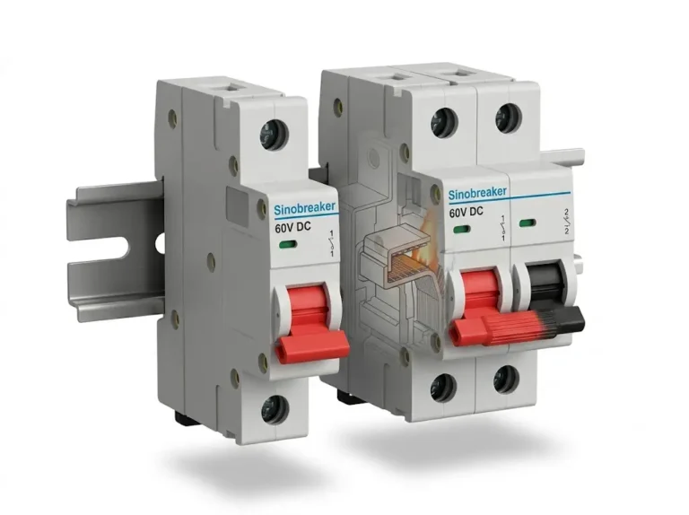
문제: Using standard AC miniature circuit breakers for DC circuits because “breaker is a breaker.”
Why this happens: Lack of understanding of DC arc extinction challenges.
결과:
– AC MCB cannot extinguish DC arc (no zero-crossing)
– Contacts weld closed during fault
– MCB fails to protect circuit—fire hazard
예방:
– Verify “DC” marking on every MCB before installation
– Check voltage rating includes “DC” (not just “VAC”)
– If MCB only shows AC voltage, it’s NOT DC-rated
– When in doubt, consult manufacturer datasheet
문제: Mounting MCBs side-by-side with no spacing to save panel space.
Why this happens: Combiner box is small, installer wants to fit more circuits.
결과:
– MCBs overheat due to insufficient air circulation
– Thermal trip occurs at lower current than rated
– Nuisance tripping during hot weather
– Shortened MCB lifespan
예방:
– Maintain 10mm minimum spacing between MCBs
– For high-current MCBs (>63A), increase spacing to 20mm
– Ensure 100mm clearance above/below MCB rows
– Consider forced ventilation (fans) if panel will be in direct sun
– Use larger enclosure if necessary—don’t compromise thermal management
문제: Installing single-pole MCBs to save money in floating (ungrounded) DC systems.
Why this happens: Installer familiar with grounded AC systems where single-pole breakers are common.
결과:
– Only one conductor disconnected during trip
– Other conductor remains at full system voltage
– Shock hazard during maintenance
– Violates NEC 690.13 for ungrounded systems
예방:
– Modern PV systems are ungrounded—always use 2-pole MCBs
– Exception: Older grounded systems (rare) can use 1-pole on ungrounded conductor only
– When unsure, use 2-pole MCBs—they work for both grounded and ungrounded systems
문제: Installing MCBs without proper circuit identification labels.
Why this happens: Installer plans to label later but forgets, or uses temporary labels that fade.
결과:
– Troubleshooting takes 3-5× longer
– Wrong circuit may be disconnected during maintenance (safety hazard)
– Fails NEC 110.22 and 690.13 requirements
– Inspection failures
예방:
– Label MCBs immediately during installation (not later)
– Use label maker with UV-resistant labels or engraved labels
– Include: circuit name, voltage, current rating
– Place labels where visible with panel door open and closed
For PV systems >1000V DC (e.g., 1200V or 1500V strings), some installations use series-connected MCBs:
When to Consider:
– System voltage exceeds available single-MCB rating
– Temporary solution until high-voltage MCBs arrive
– Existing panel upgrade to higher voltage
Installation Requirements:
1. Matched MCBs: Use identical models from same production batch
2. Voltage balancing: Install RC snubbers (10kΩ + 100nF) across each MCB
3. Mechanical linking: Use auxiliary trip bars to ensure simultaneous operation
4. Doubled spacing: Maintain 20mm between series-connected MCBs
5. Individual testing: Test each MCB independently before series connection
계산:
– Series MCBs voltage: V_total = n × V_rated × 0.85 (derating factor)
– Example: 2× 800V MCBs = 2 × 800V × 0.85 = 1,360V capacity
🎯 모범 사례: Modern 1500V-rated DC MCBs are available—specify these for new installations instead of series connections. Series MCBs add complexity and failure points.
DC surge protection devices (SPDs) should coordinate with MCBs:
Installation Sequence (top to bottom):
1. PV array input
2. DC SPD Type 2 (lightning/surge protection)
3. DC miniature circuit breaker (overcurrent protection)
4. Load/inverter output
Why this order:
– SPD diverts surge energy to ground before reaching MCB
– MCB protects SPD from follow-on current after surge
– If SPD fails short-circuit, MCB trips to isolate it
Wiring:
– SPD connects line-to-ground and line-to-line
– MCB connects in series with line conductor
– Keep SPD ground wire <300mm (12″) length for effectiveness
For extreme environments (combiner boxes in direct sun, cold climates):
Select temperature-compensated MCBs that maintain trip accuracy from -40°C to +70°C.
Additional installation measures:
– Mount MCBs on interior panel walls (not door)
– Use reflective paint or insulation on enclosure exterior
– Install ventilation fans with thermostatic control
– Monitor internal temperature with datalogger
– Consider air conditioning for critical systems

If manufacturer specifications are unavailable, use these conservative values: 10-16A MCBs use 2.0 Nm, 20-40A use 2.5 Nm, 50-80A use 3.0 Nm, 100A+ use 3.5 Nm. However, always try to obtain manufacturer specifications first—check the datasheet PDF on their website or contact technical support. Using incorrect torque risks either cracked housings (over-torque) or arcing connections (under-torque). If you regularly install a particular brand, contact your distributor for a torque specification sheet covering their entire product line.
While most DC miniature circuit breakers are designed for vertical mounting with toggle upward, many manufacturers allow mounting at any orientation. Check the MCB datasheet for “mounting position” specifications. If horizontal mounting is permitted, ensure: (1) adequate heat dissipation (hot air rises—side mounting may trap heat), (2) toggle accessibility, (3) increased derating of 5-10% may apply. For commercial installations subject to inspection, verify with AHJ that non-vertical mounting is acceptable. When in doubt, mount vertically with ON position upward—this is universally accepted.
Calculate expected internal temperature: T_internal = T_ambient + (Power_loss / Ventilation_effectiveness). Rule of thumb: if combiner box will see >50°C ambient (direct sun, desert climates), or if total MCB current exceeds 200A, install ventilation fans. Use thermostatic fans that activate at 45°C. Alternatively, perform a test: install temporary temperature loggers inside panel, operate for one week during summer, check peak temperatures. If interior exceeds 70°C, add ventilation. Proper ventilation extends MCB life by 50% and reduces nuisance tripping.
Stop immediately—do not try to force it. Options: (1) For minor damage, use a screw extractor or slightly larger bit to remove screw. Contact manufacturer for replacement screws (often available). (2) For major damage where threads are stripped, the MCB terminal is compromised—replace the entire MCB. Never use oversized screws, thread repair compounds, or “workarounds.” A compromised terminal connection will arc, overheat, and fail eventually. Document the stripped MCB for warranty claim—manufacturer defect or installer over-torquing will determine coverage.
Yes, for critical installations (commercial systems, high-value residential). Perform bench testing: (1) Continuity check—closed MCB should read <0.5Ω. (2) Manual operation—toggle should move smoothly with definite click at ON/OFF. (3) Visual inspection—no cracks, damage, or defects. (4) If you have load bank, apply rated current for 10 minutes—MCB should not trip. This catches the 1-2% of MCBs with manufacturing defects before they’re installed in hard-to-access locations. For residential installs where time is limited, at minimum perform continuity and operation checks.
Always round UP to the next standard rating, never down. Example: Calculation gives 17.5A, standard sizes are 16A and 20A—select 20A. Then verify wire ampacity supports 20A after temperature derating. If wire is marginal, you have two options: (1) upsize wire to handle 20A, or (2) use 16A MCB IF it meets NEC minimum (Isc × 1.56). Never install undersized MCB—this violates NEC and creates fire hazard. If you’re between two sizes and wire supports both, choose the larger for reliability and future capacity.
Use a dual-channel multimeter or two separate meters. Connect one to each pole. Close the MCB and measure continuity on both channels—should read <1Ω on each. Manually trip the MCB. Both channels should simultaneously go to open circuit (>10MΩ). Alternatively, energize from a safe DC source (battery bank), connect loads to both poles, and trip MCB—both loads should shut off simultaneously. If poles don’t trip together, the MCB has an internal defect and must be replaced. This is critical for ungrounded PV systems where one energized pole creates shock hazard.
Professional installation of DC miniature circuit breakers requires attention to detail, proper tools, and systematic procedures. From initial calculations and wire sizing through mounting, torquing, testing, and documentation, each step contributes to a safe, reliable, code-compliant installation.
Key Takeaways for Installers:
Pre-Installation: Calculate MCB ratings per NEC 690.8 (Isc × 1.56), verify wire ampacity after temperature derating, and plan panel layout for thermal management and accessibility.
마운팅: Ensure DIN rail is level and secure, snap MCBs firmly onto rail, maintain 10mm spacing for heat dissipation, and install end stops.
Wiring: Strip wires precisely (10-12mm), install ferrules on stranded wire, connect load side first for safety, and always use a torque screwdriver at manufacturer specifications.
Testing: Perform continuity checks (<1Ω closed, >10MΩ open), verify insulation resistance (>1MΩ), measure voltages before energization, and conduct thermal inspection after 30 minutes under load.
문서: Label all MCBs with circuit identification and ratings, create as-built drawings, photograph completed installation, and maintain test result records.
The techniques and procedures in this guide represent field-tested best practices from thousands of successful DC MCB installations. Follow these methods, avoid the common mistakes, and your installations will pass inspection, operate reliably, and require minimal service calls.
Related Installation Guides:
- DC Circuit Breaker Systems – Component selection and specifications
- DC SPD Installation – Integrating surge protection with MCBs
- PV 컴바이너 박스 배선 – Complete combiner box assembly guide
Training Resources: SYNODE offers hands-on DC MCB installation training for electrical contractors and solar installers. Contact our technical training department for regional class schedules and certification programs.
마지막 업데이트: 2025년 10월
작성자: SYNODE Field Services Team
기술 검토: Master Electricians, NABCEP-Certified PV Installation Professionals
Compliance: NEC 기사 690:2023, IEC 60364-7-712:2017