주소
304 북쪽 추기경
세인트 도체스터 센터, MA 02124
근무 시간
월요일~금요일: 오전 7시~오후 7시
주말: 주말: 오전 10시 - 오후 5시
주소
304 북쪽 추기경
세인트 도체스터 센터, MA 02124
근무 시간
월요일~금요일: 오전 7시~오후 7시
주말: 주말: 오전 10시 - 오후 5시

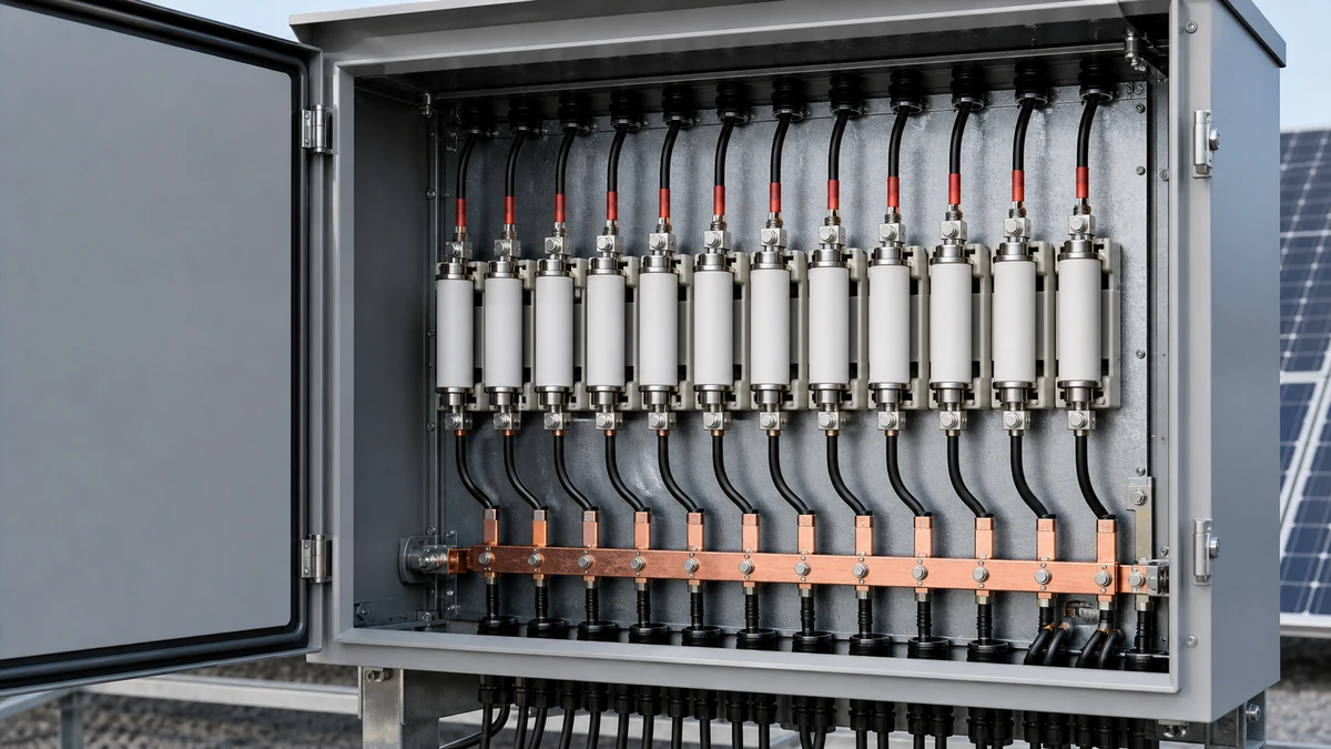
Parallel PV arrays look simple on a single-line diagram, but fault current behavior can be counterintuitive. In normal operation, each string sends current toward the inverter or charge controller. During a fault, however, healthy parallel strings can drive reverse current into the faulted string. That is why **parallel pv string fault current** is one of the key checks when selecting a DC Fuse for PV string protection.
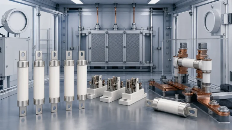
For Sinobreaker DC Fuse selection, the goal is not to choose a fuse from a shortcut table. The goal is to verify that the selected gPV fuse-link, fuse holder, conductor, module rating, and installation standard all work together under the actual PV circuit conditions.
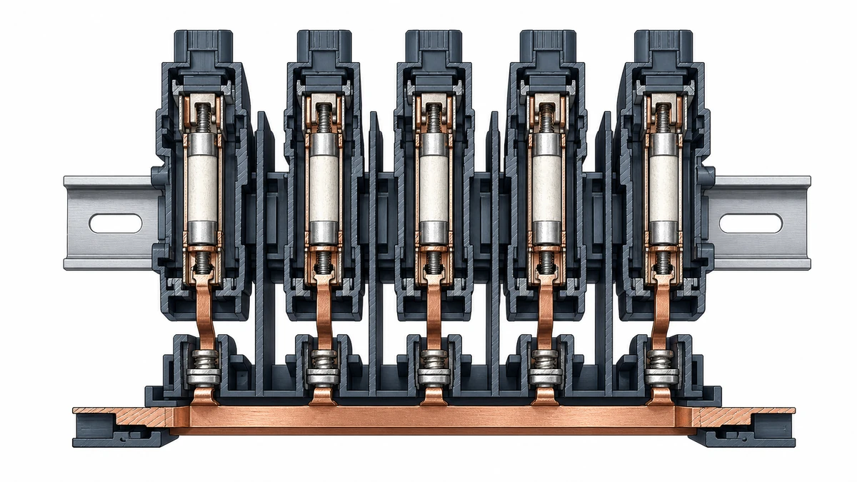
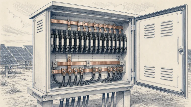
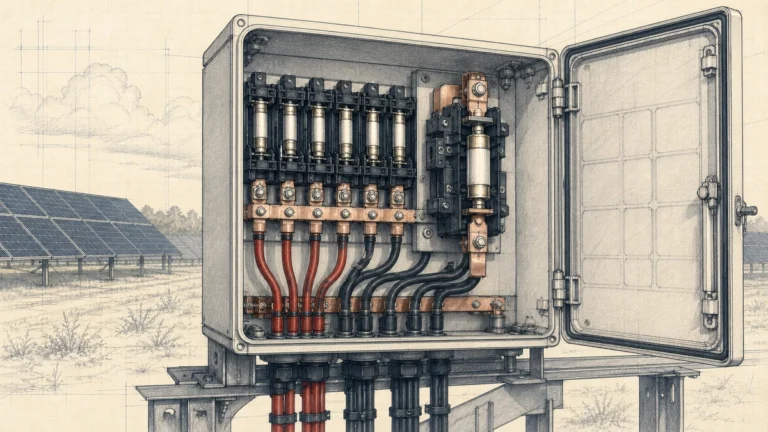
In a PV combiner, each string is a current source. If one string develops a short circuit or reverse-current path, the other strings connected in parallel can feed that fault. Littelfuse describes reverse overcurrent as current flowing back toward its source and identifies maximum circuit current and system voltage as core fuse-sizing inputs. It also notes that PV-specific fuses are required for PV conditions.
IEC 62548-1 sets design requirements for PV arrays, including DC array wiring and electrical protection devices. This means PV fuse calculations should be checked against the applicable installation standard and local jurisdiction, not treated as a universal fuse-table shortcut.
IEC 60269-6 gives supplementary requirements for fuse-links used to protect PV strings and arrays in circuits up to 1,500 V DC. Therefore, the fuse-link’s **gPV category**, rated DC voltage, current rating, breaking capacity, and coordination with the actual circuit must all be verified.
A PV string’s normal current is based primarily on the module short-circuit current, usually shown as Isc on the module data sheet. Design current may need to be adjusted for irradiance, bifacial gain, temperature assumptions, code multipliers, or local engineering rules.
A simplified design current expression is:
“text“
I_string_design = Isc_module x applicable correction factors
The applicable correction factors are not universal. They depend on the installation code, project location, module technology, and authority having jurisdiction.
When one string is faulted, the other parallel strings can contribute current into it. A practical first-pass estimate is:
“text“
I_fault_parallel = (N_parallel_strings - 1) x I_string_design
Where:
“text“
N_parallel_strings = total number of strings connected in parallel
I_string_design = corrected design current of one healthy string
This is the core **parallel pv string fault current** calculation. It estimates how much current may flow into the faulted string from the remaining healthy strings.
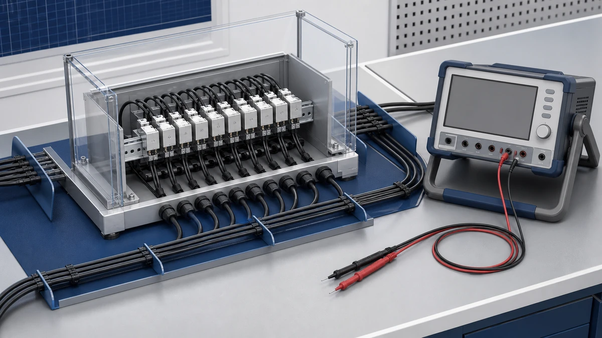
In a single-string circuit, there are no other parallel strings to backfeed the faulted string. In a two-string circuit, only one other string can contribute reverse current. In larger combiner boxes, many healthy strings can feed the fault, so the reverse current can quickly exceed the module’s maximum series fuse rating.
Even if the calculated value appears low, the final decision must still follow the applicable electrical code, module data sheet, inverter or combiner requirements, and fuse manufacturer data.
Calculate the maximum open-circuit string voltage at the lowest expected cell temperature:
“text“
V_string_max = modules_in_series x Voc_module_corrected_for_low_temperature
Then select a DC Fuse and fuse holder with a rated DC voltage equal to or greater than the maximum PV circuit voltage. For PV arrays, the fuse-link should be suitable for PV service, commonly identified as **gPV** under IEC 60269-6 for PV string and array protection.
Do not use an AC fuse or a general-purpose DC fuse unless the manufacturer explicitly rates it for the PV application, voltage, current, and fault conditions.
Determine the maximum current the string can carry during normal operation:
“text“
I_normal_max = Isc_module x required design multiplier or correction factors
The fuse current rating must be high enough to avoid nuisance operation during expected PV output, including high irradiance events and any required code multipliers.
PV modules list a maximum series fuse rating on the data sheet. The selected fuse rating must not exceed this value unless the module manufacturer provides written approval for a different arrangement.
The practical check is:
“text“
Fuse rated current <= module maximum series fuse rating
If the calculated operating-current requirement is higher than the module’s maximum series fuse rating, the design cannot be solved by simply increasing the fuse size. The array design, number of parallel strings, module choice, or protection scheme must be reviewed.
Estimate the reverse current contribution from the healthy strings:
“text“
I_fault_parallel = (N_parallel_strings - 1) x I_string_design
Then compare this value with the module maximum series fuse rating, conductor ampacity, fuse operating characteristics, and the selected fuse-link’s data sheet.
If the calculated reverse current can exceed the module’s safe limit, string fusing is normally required. The fuse must be able to interrupt the prospective DC fault current under PV conditions.
The selected gPV fuse must have adequate DC breaking capacity for the maximum prospective fault current. This is especially important in larger arrays, energy storage coupled systems, and DC architectures where additional sources may contribute fault current.
Also verify:
“text“
Fuse-link category: gPV for PV protection
Rated DC voltage: equal to or above maximum circuit voltage
Rated current: suitable for normal string current
Breaking capacity: suitable for prospective DC fault current
Fuse holder rating: compatible with fuse-link and DC voltage
Conductor rating: coordinated with overcurrent protection
Module limit: fuse rating does not exceed maximum series fuse rating
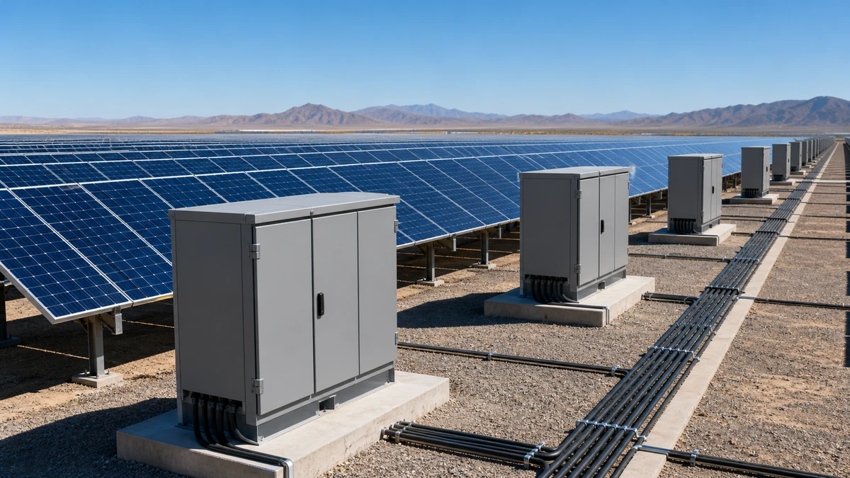
Assume the following PV string data:
“text“
Module Isc: 13.8 A
Module maximum series fuse rating: 25 A
Strings in parallel: 10
Modules per string: 18
Module Voc: 49.5 V
Lowest-temperature voltage correction factor: 1.098
Design current multiplier: 1.25
“text“
V_string_max = 18 x 49.5 V x 1.098
V_string_max = 978.3 V DC
A 1,000 V DC rated gPV fuse may appear sufficient by voltage in this simplified example, but the real design should include all required tolerances and code assumptions. If the project is designed on a 1,500 V DC platform, then a 1,500 V DC rated fuse system would be required.
“text“
I_string_design = 13.8 A x 1.25
I_string_design = 17.25 A
The fuse must carry the expected continuous PV current without nuisance operation, subject to the applicable standard and manufacturer derating instructions.
“text“
I_fault_parallel = (10 - 1) x 17.25 A
I_fault_parallel = 155.25 A
The faulted string may be exposed to approximately 155 A from the other nine strings. This is much higher than the module’s 25 A maximum series fuse rating, so string-level overcurrent protection is required.
If the applicable design method and fuse data sheet allow it, a 25 A gPV fuse may be a candidate because:
“text“
25 A <= 25 A module maximum series fuse rating
25 A > 17.25 A design string current
However, this is only a candidate. The final selection must be checked against the Sinobreaker DC Fuse data sheet, fuse holder rating, rated DC voltage, breaking capacity, ambient temperature, enclosure conditions, cable ampacity, combiner configuration, and local installation code.
DC arcs do not naturally pass through zero current like AC arcs do. A fuse used in a PV array must be rated for the actual DC voltage and PV fault behavior. IEC 60269-6 exists because PV fuse-links have specific requirements for string and array protection.
The module maximum series fuse rating is a hard coordination point. Selecting a larger fuse to avoid nuisance blowing can leave the module unprotected during reverse-current faults.
The faulted string is usually not the only current path. The healthy parallel strings can feed the fault. That is why the calculation uses:
“text“
N_parallel_strings - 1
not the total number of strings and not just one string unless only one healthy parallel string exists.
A numeric example is useful for understanding the method, but it is not a substitute for the applicable design code, installation standard, or manufacturer coordination study. PV fuse selection must reconcile module limits, string current, possible contribution from parallel strings, and the selected device’s data sheet.
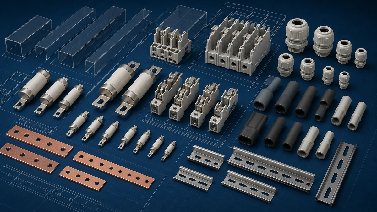
Before approving a Sinobreaker DC Fuse for a PV combiner or string circuit, confirm:
“text“
PV fuse type: gPV
Rated DC voltage: suitable for maximum PV circuit voltage
Rated current: suitable for corrected string current
Breaking capacity: suitable for prospective DC fault current
Module coordination: not above maximum series fuse rating
Fuse holder compatibility: matched to fuse size and rating
Installation conditions: checked for temperature and enclosure derating
The project file should include:
“text“
PV module data sheet
String voltage calculation
String current calculation
Parallel pv string fault current calculation
Selected fuse-link data sheet
Fuse holder or combiner data sheet
Applicable code or standard reference
Coordination or protection notes
This documentation helps installers, inspectors, EPC teams, and maintenance personnel understand why the selected DC Fuse is suitable for the actual PV array.
Parallel PV string fault current is the reverse current that healthy parallel strings can feed into a faulted string. A practical estimate is the number of healthy parallel strings multiplied by the corrected design current of one string.
A PV string generally needs a gPV fuse when reverse current from parallel strings can exceed the module’s maximum series fuse rating or when required by the applicable installation code, combiner design, or equipment manufacturer. The fuse must be PV-rated, correctly sized, and coordinated with the module and conductor ratings.
Not automatically. Even similar arrays can have different module Isc values, maximum series fuse ratings, string counts, voltage ratings, ambient conditions, and jurisdictional requirements. Each project should verify the parallel pv string fault current calculation and the selected DC Fuse data sheet before reuse.