Endereço
304 North Cardinal
St. Dorchester Center, MA 02124
Horas de trabalho
De segunda a sexta-feira: das 7h às 19h
Fim de semana: 10:00 - 17:00
Endereço
304 North Cardinal
St. Dorchester Center, MA 02124
Horas de trabalho
De segunda a sexta-feira: das 7h às 19h
Fim de semana: 10:00 - 17:00

Um fusível de painel solar fornece proteção crítica contra sobrecorrente que evita danos ao equipamento e riscos de incêndio em sistemas fotovoltaicos. Compreender a seleção, o dimensionamento e a instalação adequados do fusível do painel solar garante que o seu painel fotovoltaico opere com segurança, atendendo aos requisitos do Código Elétrico Nacional e protegendo seu investimento em energia solar.
Este guia abrangente cobre tudo o que os instaladores e projetistas de sistemas precisam saber sobre fusíveis de painéis solares, desde classificações de gPV e cálculos de dimensionamento até erros comuns de instalação que anulam garantias e criam riscos à segurança.
Os fusíveis de painéis solares devem lidar com características elétricas exclusivas de CC que os fusíveis de CA padrão não podem interromper com segurança. Ao proteger equipamentos fotovoltaicos, fusíveis especializados Fusíveis CC projetados para aplicações solares garantem proteção confiável em condições operacionais desafiadoras.
Principais diferenças em relação aos fusíveis CA:
Os desafios de extinção de arco CC tornam-se significativamente mais difíceis do que a proteção CA. Nos circuitos CA, a corrente cruza naturalmente o zero 120 vezes por segundo, ajudando a extinguir os arcos. A corrente CC mantém a polaridade constante, criando arcos contínuos que exigem projetos de fusíveis especializados para interromper com segurança.
As classificações gPV específicas para energia fotovoltaica abordam as características dos painéis solares, incluindo condições de corrente reversa, altas correntes de surto durante os efeitos de borda de nuvem e o comportamento exclusivo da curva IV dos módulos fotovoltaicos. Os fusíveis padrão não possuem os testes e a construção necessários para esses cenários.
Os coeficientes de temperatura afetam o desempenho do fusível de forma diferente em instalações em telhados, onde a temperatura ambiente pode exceder 70°C (158°F). Os fusíveis com classificação solar são submetidos a testes em temperaturas extremas para garantir uma operação confiável em espaços quentes no sótão e em caixas combinadoras montadas no telhado.
Principais percepções: De acordo com Normas IEC 60269-6Os fusíveis classificados como gPV devem passar por 22 testes específicos, incluindo interrupção de corrente reversa e cenários de rastreamento de ponto de potência máxima que não se aplicam a fusíveis CC de uso geral.
A designação "gPV" indica um fusível projetado e testado especificamente para aplicações fotovoltaicas. Essa classificação, definida em IEC 60269-6 e reconhecido por UL 2579O fusível de alta qualidade, que garante que o fusível proteja com segurança os painéis solares em todas as condições de operação.
O que a certificação gPV garante:
O fusível pode interromper as correntes reversas que fluem de uma string saudável para uma string com defeito. Em matrizes de vários strings, um string em curto pode extrair corrente de strings paralelos, criando condições de corrente reversa que excedem a corrente operacional direta.
Capacidade de interrupção de alta tensão CC em tensões de sistema de 600 V CC a 1500 V CC. Como as instalações em escala de serviços públicos adotam arquiteturas de 1500 V, as classificações dos fusíveis devem corresponder ou exceder a tensão máxima do sistema.
A coordenação com as classificações do módulo e do condutor garante que o fusível proteja o equipamento a jusante sem operação incômoda. A energia de passagem do fusível (classificação I²t) deve ser menor do que as classificações de resistência do cabo e do módulo.
⚠️ Importante: O uso de fusíveis não classificados como gPV em aplicações solares viola Artigo 690.9 do NEC e cria sérios riscos à segurança. Os fusíveis CC padrão automotivos ou de uso geral não podem interromper com segurança as correntes de falha PV e podem explodir em condições de corrente reversa.
Os fusíveis de string individuais protegem cada string do painel solar em configurações paralelas. NEC 690.9(A) requer proteção contra sobrecorrente quando três ou mais strings são conectadas em paralelo.
A fusão de cordas protege contra:
Cada string normalmente usa fusíveis de 10A a 20A, dependendo das classificações de corrente de curto-circuito (Isc) do módulo. O dimensionamento do fusível deve levar em conta o multiplicador de 1,56x exigido pela NEC 690.8(A)(1).
Os fusíveis ou disjuntores da matriz principal fornecem proteção de backup entre a saída da caixa combinadora e a entrada do controlador de carga ou do inversor. Essa proteção protege contra:
Falhas no equipamento downstream:
Os fusíveis principais normalmente variam de 30 A a 300 A para sistemas residenciais e comerciais. A coordenação adequada exige que o fusível principal seja classificado como mais alto do que os fusíveis de string individuais para garantir a operação seletiva.
Pode ser necessário um fusível adicional em locais específicos do equipamento:
Conexões da bateria: Os fusíveis entre a saída do controlador de carga e o banco de baterias evitam que as correntes de curto-circuito da bateria danifiquem o equipamento. Os fusíveis de bateria normalmente variam de 100A a 400A, dependendo do tamanho do banco.
Sistemas otimizadores de CC: Algumas arquiteturas de microinversores e otimizadores exigem fusíveis em nível de módulo, embora muitos fabricantes usem proteção interna.
Equipamento de monitoramento: Os sensores de corrente e os circuitos de monitoramento podem precisar de fusíveis de baixa corrente (normalmente de 1A a 5A) para proteção.
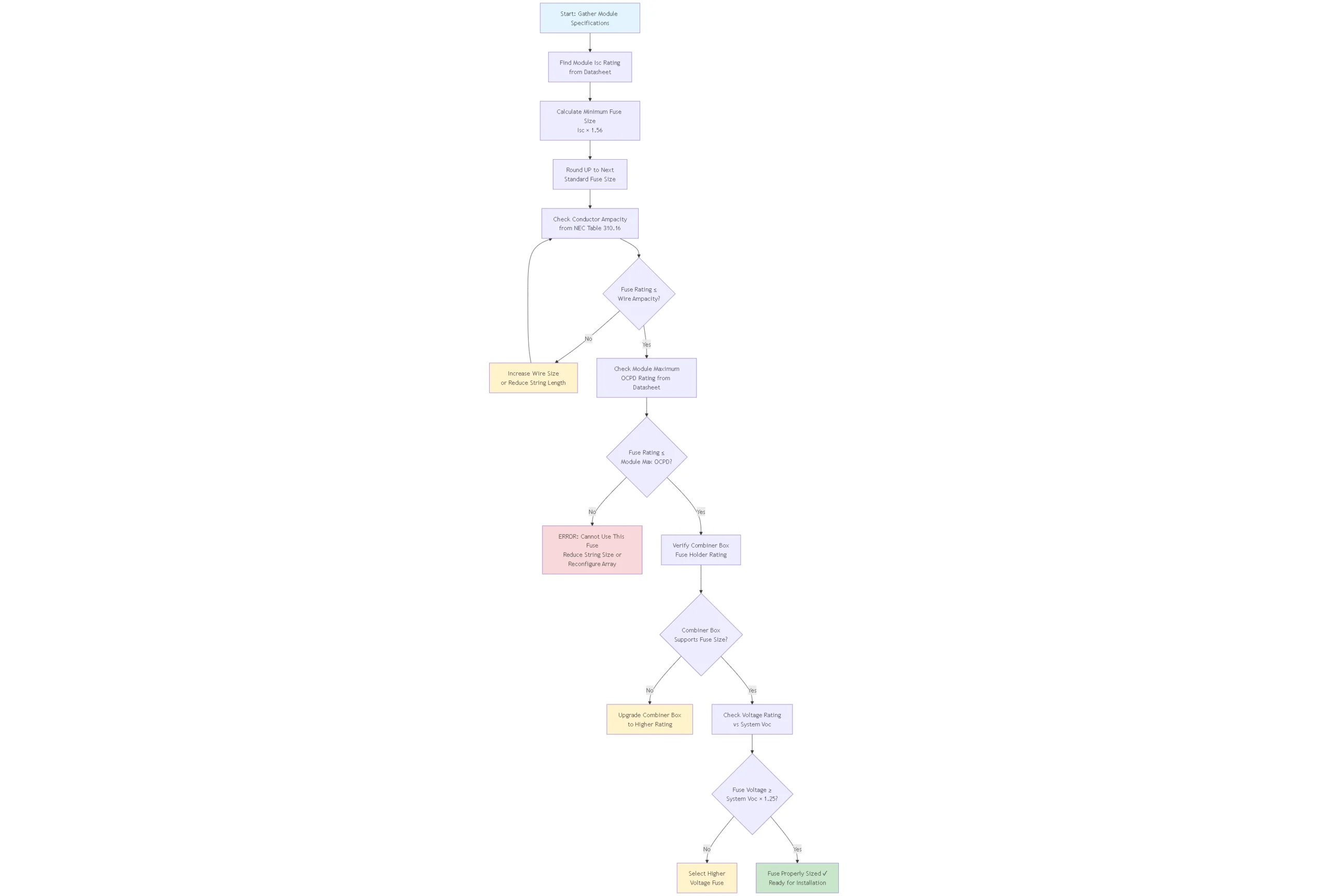
NEC 690.8(A)(1) requer o dimensionamento de condutores e dispositivos de sobrecorrente a 156% de corrente de curto-circuito sob condições de teste padrão. Isso leva em conta:
Variação da irradiância: A irradiância solar pode exceder 1000 W/m² durante os efeitos de borda de nuvem, onde a luz solar direta e refletida se combinam, aumentando temporariamente a saída do módulo 15-25% acima do Isc nominal.
Efeitos da temperatura: Os dias frios e ensolarados de inverno podem aumentar o Voc e, ao mesmo tempo, manter a saída de corrente alta, sobrecarregando os dispositivos de proteção.
Fatores de envelhecimento: O desempenho do módulo varia com o tempo, e o multiplicador fornece uma margem de segurança para os padrões de degradação.
Fórmula de cálculo: Classificação mínima do fusível = Isc do módulo × 1,56
Exemplo de cálculo:
Nunca arredonde para baixo ao selecionar as classificações dos fusíveis. O uso de um fusível de 15A neste exemplo violaria o código e criaria uma operação incômoda do fusível durante condições de alta irradiância.
Embora o dimensionamento mínimo siga a regra de 1,56x, o tamanho máximo do fusível é limitado pela ampacidade do condutor e pelas classificações do equipamento:
Proteção do condutor: A classificação do fusível não pode exceder a ampacidade do condutor por NEC 690.9(B). Para o fio 10 AWG USE-2 classificado como 40A, o fusível máximo seria de 40A.
Classificação do módulo OCPD: As folhas de dados dos módulos especificam as classificações máximas dos dispositivos de proteção contra sobrecorrente, normalmente de 15A a 25A para módulos residenciais. Nunca exceda essa classificação, mesmo que o tamanho do fio permita isso.
Classificação da caixa combinadora: Os porta-fusíveis e os barramentos nas caixas combinadoras têm classificações máximas de corrente que não podem ser excedidas. As caixas combinadoras padrão suportam fusíveis de 15A a 30A por posição de string.
Em configurações somente em série (um ou dois strings), o fusível pode não ser necessário por NEC 690.9(A). No entanto, muitos instaladores incluem a fusão para:
Segurança na manutenção: A desconexão com fusível permite o isolamento seguro do string durante a manutenção sem desligar todo o array.
Expansibilidade futura: A fusão pré-instalada simplifica a adição posterior de strings paralelas sem a necessidade de reprojetar o sistema.
Proteção adicional: Oferece proteção contra sobrecorrente para a fiação a jusante, mesmo em configurações somente em série.
Os fusíveis solares estão disponíveis em classificações de corrente padrão que correspondem às configurações comuns de módulos:
| Classificação do fusível | Isc máximo do módulo | Aplicação típica | Tamanho do sistema |
|---|---|---|---|
| 10A gPV | 6.4A | Módulos mais antigos/menores | Residencial |
| 15A gPV | 9.6A | Módulos padrão de 300-350 W | Residencial/comercial de pequeno porte |
| 20A gPV | 12.8A | Módulos modernos de 370-450 W | Residencial/Comercial |
| 25A gPV | 16.0A | Módulos de 500W+ de alta potência | Comercial |
| 30A gPV | 19.2A | Proteção da matriz principal | Residencial 2-3 strings |
| 40A gPV | 25.6A | Proteção da matriz principal | Comercial 3-4 cordas |
| 50A gPV | 32.0A | Proteção da matriz principal | Comercial 4-5 cordas |
| 63A+ gPV | 40.4A+ | Rede elétrica de grande porte | Escala de utilidade |
Os fusíveis do painel solar devem ser classificados para a tensão máxima do sistema com margem de segurança:
Fusíveis de 600V CC: Sistemas residenciais (máximo típico de 300-450 V)
Fusíveis de 1000 V CC: Sistemas comerciais (máximo típico de 600-850 V)
Fusíveis de 1500V CC: Sistemas em escala de utilidade pública (máximo típico de 1200-1400 V)
Sempre selecione a tensão nominal do fusível pelo menos 25% maior do que a tensão máxima de circuito aberto do sistema (Voc) na temperatura mais baixa esperada. Manhãs frias e ensolaradas podem elevar a Voc 15-20% acima dos valores nominais.
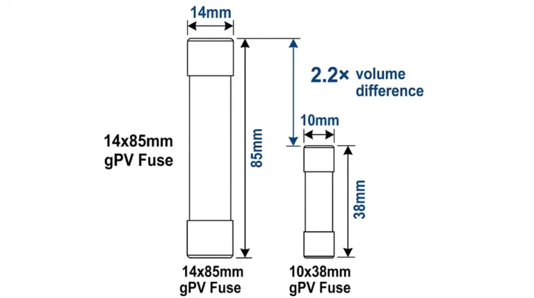
O tipo mais comum para instalações solares residenciais e comerciais, os fusíveis cilíndricos gPV usam tamanhos padrão de 10×38 mm ou 14×51 mm, dependendo da classificação de corrente.
Especificações físicas:
Características da construção:
Algumas caixas combinadoras residenciais usam fusíveis de lâmina no estilo automotivo com classificações gPV. Eles oferecem:
Vantagens:
Limitações:
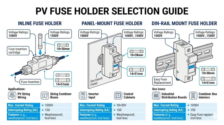
Adequado proteção solar por fusível requer porta-fusíveis com classificação UL e IEC projetados para serviços de CC:
Suportes para montagem em trilho DIN: Projetos modulares com economia de espaço para a instalação de caixas combinadoras. Cada suporte acomoda um fusível cilíndrico com fácil acesso para substituição.
Blocos de fusíveis para montagem em painel: Blocos de terminais de parafuso tradicionais para instalação permanente. Geralmente incluem indicação de fusível queimado por meio de LED ou sinalizador mecânico.
Porta-fusíveis em linha: Usado para conexões de bateria e proteção de equipamentos. Normalmente classificado como 30A a 200A com gabinetes à prova de intempéries.
Projetos seguros ao toque: Necessário em locais acessíveis por NEC 690.15. As tampas evitam o contato acidental com os terminais energizados durante a substituição do fusível.
A instalação adequada garante uma operação confiável e uma manutenção segura:
Requisitos de espaçamento:
Orientação: A maioria dos porta-fusíveis funciona em qualquer posição, mas a montagem vertical com as conexões para baixo evita o acúmulo de umidade em instalações externas.
Acessibilidade: NEC 690.15 requer meios de desconexão prontamente acessíveis. Instale os fusíveis onde eles possam ser substituídos com segurança sem subir em telhados ou entrar em áreas de equipamentos energizados.
Especificações de torque do terminal:
O aperto insuficiente cria conexões de alta resistência que aquecem sob carga. O aperto excessivo danifica os terminais e os condutores. Use uma chave de fenda com torque calibrado para conexões críticas.
Preparação do condutor: Descarne o isolamento do fio de 10 a 12 mm para terminais de parafuso. Use ponteiras em fios trançados para evitar a quebra dos fios e garantir um contato sólido. Aplique um composto antioxidante nos condutores de alumínio.
Redução de temperatura: Os fusíveis instalados em ambientes quentes (telhados, sótãos) têm sua capacidade de condução de corrente reduzida. As classificações padrão se aplicam a um ambiente de 25°C (77°F). Para instalações que excedam 40°C:
Na prática, selecione o próximo tamanho de fusível padrão maior quando o ambiente exceder 50 °C para manter a proteção adequada.
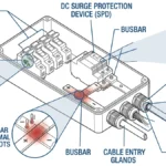
Proteção contra umidade: Use caixas combinadoras com classificação IP65 ou superior para instalações externas de fusíveis. As tampas individuais do porta-fusível oferecem proteção adicional em ambientes de alta umidade ou costeiros.
Exposição aos raios UV: Os gabinetes das caixas combinadoras devem usar materiais estabilizados contra raios UV. A luz solar direta degrada os plásticos desprotegidos em um período de 2 a 3 anos, criando rachaduras e caminhos para a entrada de água.
❌ Uso de fusíveis automotivos ou de CC padrão em vez de fusíveis com classificação gPV: Os fusíveis automotivos não podem interromper com segurança as correntes PV reversas e podem explodir em condições de falha. Isso viola a norma NEC 690.9 e anula as garantias do equipamento.
❌ Superdimensionamento de fusíveis além das classificações OCPD do módulo: A instalação de um fusível de 30A em módulos classificados para OCPD máximo de 15A cria um sério risco de incêndio. O fusível não protegerá os módulos contra falhas internas ou pontos quentes.
❌ Subdimensionamento para "economizar" módulos: Alguns instaladores usam fusíveis menores que os cálculos NEC 1.56x na esperança de evitar danos ao módulo. Isso cria uma operação incômoda e constante do fusível durante os períodos de alta irradiância e reduz a produção do sistema.
❌ Mistura de marcas/tipos de fusíveis em cadeias paralelas: Características diferentes dos fusíveis causam compartilhamento desigual de corrente e falha prematura dos fusíveis mais rápidos. Use fusíveis idênticos (mesmo fabricante, classificação e número de peça) para todas as cadeias paralelas.
❌ Instalação de fusíveis sem suportes em caixas de junção: Os clipes de fusíveis nus sem suportes adequados violam os requisitos de segurança ao toque da NEC e criam sérios riscos de choque durante a substituição.
❌ Negligenciar a verificação da classificação de tensão: Um fusível de 600 V CC em um sistema de 1.000 V fará um arco externo durante a interrupção da falha, podendo causar incêndio ou destruição do equipamento. Sempre verifique se a classificação de tensão corresponde ou excede o máximo do sistema.
A coordenação adequada da proteção garante que apenas o fusível mais próximo de uma falha funcione, deixando o restante do sistema on-line:
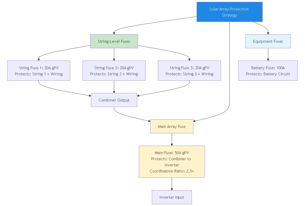
Objetivo: O fusível da string deve abrir antes do fusível da matriz principal durante falhas na string.
Taxa de coordenação: O fusível principal deve ser classificado pelo menos duas vezes a classificação do maior fusível de string para uma seletividade confiável.
Exemplo:
Os fabricantes de fusíveis publicam curvas de tempo-corrente que mostram o tempo de operação versus o nível de corrente. Para uma coordenação adequada:
Revisar curvas para:
O tempo máximo de liberação do fusível de cadeia deve ser menor do que o tempo mínimo de fusão do fusível principal em todos os níveis de corrente. Isso garante que o fusível de cadeia seja totalmente eliminado antes que o fusível principal comece a operar.
Dica profissional: Solicite as curvas de tempo e corrente de seu Fusíveis com classificação PV fornecedor durante a especificação. Sobreponha as curvas da string e do fusível principal para verificar a separação adequada (relação de tempo mínima de 2-3×) em toda a faixa de corrente.
Inspeção visual anual:
Testes elétricos semestrais:
Protocolos de segurança:
Nunca substitua fusíveis queimados sem identificar e corrigir a causa principal. A operação repetida do fusível indica falhas na fiação, problemas no módulo ou dimensionamento incorreto que exigem investigação.
Substitua imediatamente:
Investigue antes de substituir:
As instalações em escala de serviços públicos adotam cada vez mais arquiteturas de 1500 V CC para obter ganhos de eficiência. A fusão desses sistemas requer atenção especial:
Requisitos de capacidade de ruptura mais altos: As correntes de falha em grandes matrizes podem exceder 50kA. Os fusíveis devem ter capacidade de interrupção (corrente nominal de curto-circuito) de pelo menos 30kA, preferencialmente 50kA+ para instalações grandes.
Medidas de segurança aprimoradas: A 1500 V, os riscos de arco elétrico aumentam drasticamente. Os sistemas de comutação de fusíveis operados remotamente eliminam a exposição do pessoal durante as operações.
Alternativas de fusão de cordas: Alguns projetos de 1500 V usam disjuntores em vez de fusíveis no nível do string para permitir a operação remota e a eliminação de peças de reposição consumíveis.
A eletrônica de potência em nível de módulo altera os requisitos tradicionais de fusíveis:
Sistemas otimizadores: Muitos fabricantes recomendam a fusibilidade somente no nível do combinador, confiando na proteção interna do otimizador para falhas no nível do módulo. Verifique os requisitos do fabricante antes de adicionar fusíveis de string.
Sistemas de microinversores: Essas arquiteturas acopladas à CA eliminam totalmente os fusíveis de CC. Cada microinversor inclui proteção integral contra sobrecorrente e funcionalidade GFCI.
Projetos híbridos: Os sistemas que misturam inversores de string com cobertura parcial do otimizador exigem uma coordenação cuidadosa da proteção em vários níveis.
Preciso de fusíveis se tiver apenas duas cadeias de painéis solares em paralelo?
De acordo com NEC 690.9(A)Quando apenas dois strings são conectados em paralelo, os fusíveis não são necessários, pois a corrente reversa máxima não pode exceder a ampacidade do condutor. No entanto, muitos instaladores adicionam fusíveis de qualquer forma para segurança, capacidade de expansão futura e solução de problemas mais fácil. O pequeno custo adicional proporciona benefícios significativos.
Posso usar fusíveis CC comuns em vez dos caros fusíveis com classificação gPV?
Não. Os fusíveis CC padrão não podem interromper com segurança as correntes fotovoltaicas reversas e podem explodir durante condições de falha. Somente fusíveis testados e certificados para IEC 60269-6 e UL 2579 devem ser usados em aplicações solares. A diferença de custo é mínima em comparação com o risco potencial de incêndio e a responsabilidade.
Com que frequência os fusíveis do painel solar devem ser substituídos?
Os fusíveis gPV não requerem substituição de rotina, a menos que operem durante uma condição de falha. A substituição preventiva entre 10 e 15 anos leva em conta a possível corrosão do contato e a degradação interna em ambientes adversos. Inspecione anualmente e substitua se houver descoloração, abaulamento ou dano físico.
Qual é a diferença entre a capacidade de interrupção do fusível e a corrente nominal?
A corrente nominal é a corrente contínua máxima que o fusível carrega com segurança indefinidamente. A capacidade de interrupção (também chamada de capacidade de interrupção ou classificação de curto-circuito) é a corrente de falha máxima que o fusível pode interromper com segurança sem explodir. Um fusível de 20A pode ter capacidade de interrupção de 600V/10kA, o que significa que ele transporta 20A continuamente, mas pode interromper correntes de falha de até 10.000A.
Por que meus fusíveis solares queimaram durante uma tempestade?
Os surtos induzidos por raios podem gerar sobrecorrentes transitórias que excedem as classificações dos fusíveis. Embora os fusíveis ofereçam alguma proteção contra surtos, os dispositivos dedicados de proteção contra surtos fornecem proteção primária contra raios. Os fusíveis agiram corretamente ao se abrirem durante o evento de surto, evitando danos ao equipamento. Instale SPDs CC de acordo com NEC 690.35 para evitar a operação futura do fusível durante tempestades.
Posso misturar diferentes marcas de fusíveis em meu painel solar?
Embora não seja explicitamente proibido pelo código, a mistura de marcas de fusíveis cria uma coordenação imprevisível devido às diferentes características de tempo e corrente. A prática recomendada usa fusíveis idênticos (mesmo fabricante, número de peça e lote de produção, quando possível) para todas as posições de string para garantir o compartilhamento igual de corrente e proteção consistente.
O que devo fazer se o fusível de uma corda continuar queimando?
A operação repetida do fusível indica uma falha que requer investigação, não apenas substituição. As causas comuns incluem isolamento danificado do cabo, conexões soltas que criam alta resistência, falhas internas do módulo ou polaridade invertida. Isole a cadeia afetada, inspecione todas as conexões e cabos e meça a resistência do isolamento antes de reenergizar. Nunca substitua os fusíveis sem identificar a causa principal.
A seleção e a instalação adequadas do fusível do painel solar protegem seu investimento fotovoltaico e, ao mesmo tempo, garantem a conformidade com os códigos e a segurança do sistema. Compreender as diferenças críticas entre os fusíveis com classificação gPV e os dispositivos de sobrecorrente padrão evita erros dispendiosos e possíveis riscos à segurança.
As principais considerações incluem o cálculo das classificações dos fusíveis usando o multiplicador NEC 1,56x, a seleção de fusíveis com classificação gPV apropriada para a tensão do sistema, a garantia da coordenação adequada entre a proteção da string e da matriz principal e o cumprimento das práticas recomendadas de instalação para montagem, torque e proteção ambiental.
Seja no projeto de um sistema de telhado residencial ou de um parque solar em escala de serviços públicos, investir em uma proteção de sobrecorrente fotovoltaica de qualidade da SYNODE garante uma operação confiável e um desempenho de longo prazo do sistema.