Endereço
304 North Cardinal
St. Dorchester Center, MA 02124
Horas de trabalho
De segunda a sexta-feira: das 7h às 19h
Fim de semana: 10:00 - 17:00
Endereço
304 North Cardinal
St. Dorchester Center, MA 02124
Horas de trabalho
De segunda a sexta-feira: das 7h às 19h
Fim de semana: 10:00 - 17:00

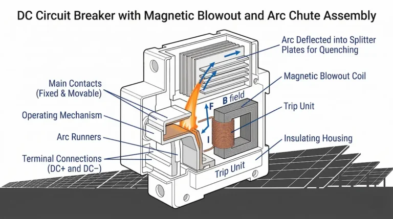
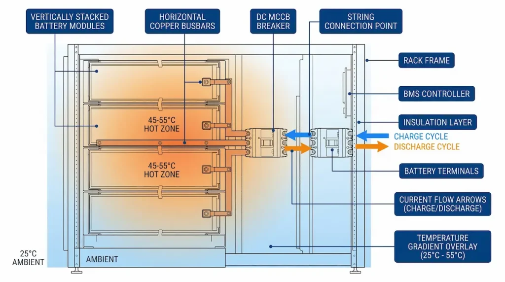
A DC circuit breaker for ESS serves as the primary fault isolation device between battery modules and power conversion systems. Unlike AC protection, ESS-rated DC breakers must extinguish arcs without zero-crossing assistance—requiring magnetic blowout coils, extended arc chutes, and contact materials rated for 1000–1500 VDC continuous operation. In a 20 MWh lithium-ion ESS project in Jiangsu Province (2023), proper DC breaker coordination reduced fault isolation time from 45 minutes of manual disconnect procedures to under 8 seconds per affected rack, directly limiting thermal runaway propagation risk.
This guide covers voltage and current selection, breaking capacity requirements, installation best practices, and environmental considerations for battery storage protection.
Battery storage protection operates under conditions fundamentally different from conventional AC or even solar PV applications. ESS DC circuit breakers handle bidirectional current flow during charge and discharge cycles—typically 100 A to 630 A continuous per string—with polarity reversals reaching 10,000 cycles annually in frequency regulation installations.
Lithium-ion battery packs deliver prospective fault currents far exceeding nominal discharge rates. A typical 1500 VDC battery string generates 15–25 kA peak fault current within the first 2 milliseconds of a short circuit. The absence of natural current zero-crossing means arc interruption relies entirely on magnetic blowout mechanisms generating field strengths of 80–150 mT to elongate and cool the arc within ceramic chute assemblies.
Standard AC breakers fail in these conditions. They wait for zero-crossing that never arrives, allowing sustained arcing that damages contacts and risks enclosure failure.
Field measurements across grid-scale ESS facilities show ambient temperatures inside battery containers reaching 45°C during peak summer operation. Breakers must maintain rated performance from −25°C to +60°C per IEC 60947-2 Annex M requirements for DC applications. Selecting breakers without understanding these operational demands leads to nuisance tripping, protection gaps, or catastrophic failure during actual faults.
For comprehensive DC circuit breaker specifications suited to energy storage applications, see the DC Circuit Breaker product range at Sinobreaker.
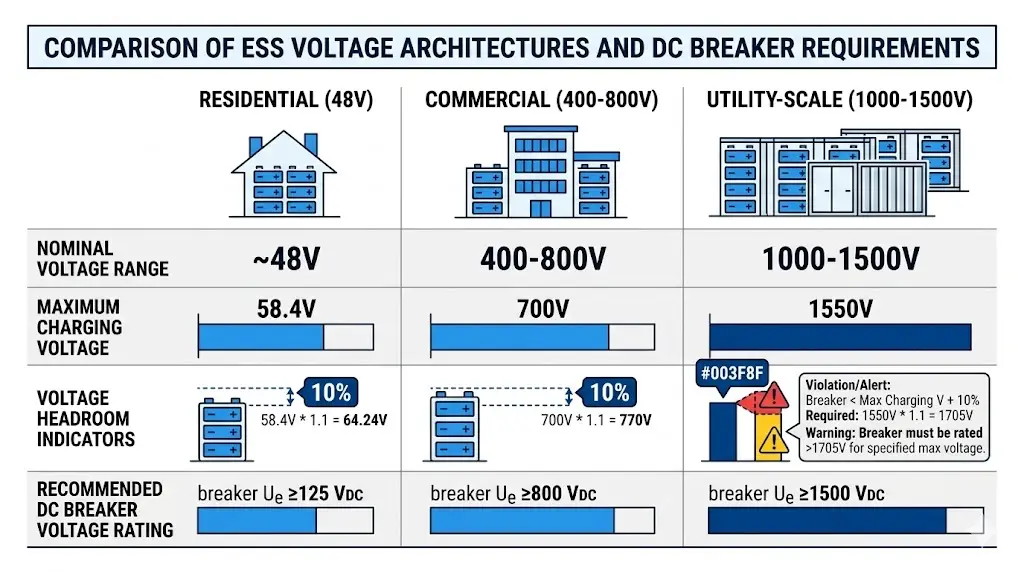
Matching DC circuit breaker ratings to battery architecture requires understanding both nominal system voltage and worst-case operating conditions. ESS voltage classes vary significantly across application scales.
| ESS Application | Nominal Voltage | Max Charging Voltage | Minimum Breaker Ue |
|---|---|---|---|
| Residential (LFP) | 48–51.2 VDC | 58.4 VDC | 125 VDC |
| Commercial rack | 400–600 VDC | 700 VDC | 800 VDC |
| Utility container | 1000–1500 VDC | 1550 VDC | 1500 VDC |
The breaker’s rated operational voltage (Ue) must exceed maximum possible battery voltage under all conditions—including equalization charging, cell imbalance, and regenerative events from grid disturbances.
Size breaker current ratings based on continuous discharge at maximum C-rate, plus allowances for inverter inrush (typically 1.5× for 10 seconds) and ambient temperature derating.
A 280 Ah LFP cell string at 1C discharge delivers 280 A continuous. With 45°C ambient derating (0.9 factor) and 10% safety margin, specify minimum 350 A breaker rating. For high-current ESS applications, DC MCCB series breakers provide ratings from 125 A to 1600 A at voltages up to 1500 VDC.
[Expert Insight: Voltage Headroom in ESS Design]
- Always specify breaker Ue at least 10% above maximum battery charging voltage
- Cell imbalance during aging can push string voltage 3–5% above nominal maximum
- Regenerative events from grid faults may cause transient overvoltage spikes
- When in doubt, select the next higher voltage class—cost difference is minimal compared to failure risk
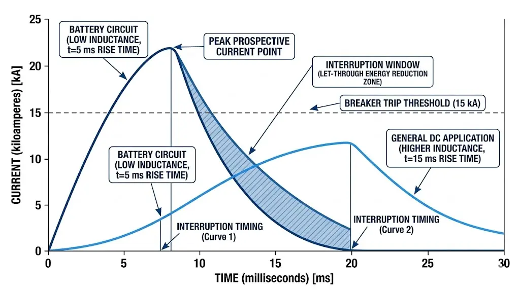
Breaking capacity—the maximum fault current a breaker can safely interrupt—becomes critical in ESS applications where low-impedance lithium cells deliver extreme short-circuit currents.
A typical 280 Ah LFP cell has internal resistance around 0.3–0.5 mΩ. For a 16-cell string (51.2 V nominal):
This current develops within 2–5 milliseconds. The breaker must interrupt before thermal damage occurs.
DC circuits have an L/R time constant determining fault current rise rate. IEC 60947-2 Annex M specifies standard test conditions at 15 ms time constant for general DC applications. Battery circuits with minimal inductance may exhibit 5 ms or faster time constants.
Breakers tested only at 15 ms may underperform in battery applications. Always verify the manufacturer’s declared L/R time constant matches your installation characteristics.
| ESS Scale | Typical Fault Current | Minimum Icu Required |
|---|---|---|
| Residential (5–10 kWh) | 3–8 kA | 10 kA |
| Commercial (100–500 kWh) | 15–30 kA | 36 kA |
| Utility (1+ MWh) | 30–50 kA | 50 kA+ |
Two primary DC breaker formats serve ESS applications. Selection depends on current rating, breaking capacity requirements, and installation constraints.
DC miniature circuit breakers suit applications where space efficiency matters and fault currents remain moderate:
A 48 V residential battery system with 100 A maximum discharge pairs well with a 2-pole DC MCB rated 125 VDC/63 A. Explore DC MCB series options for residential and light commercial applications.
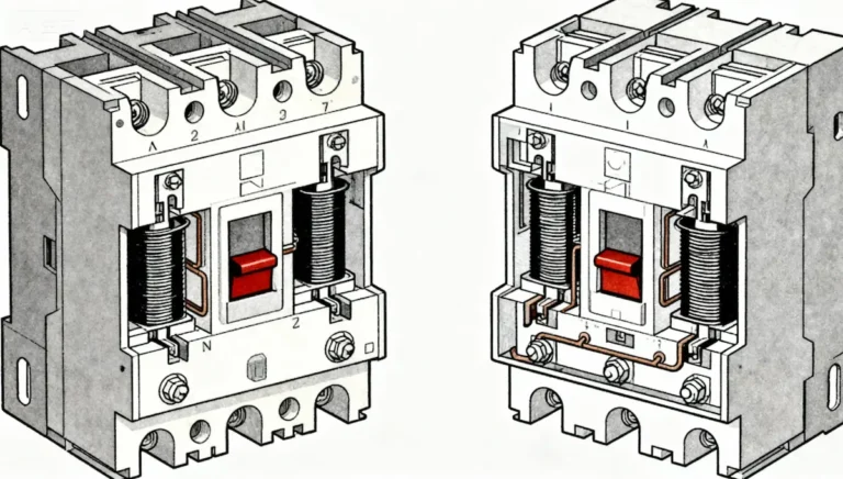
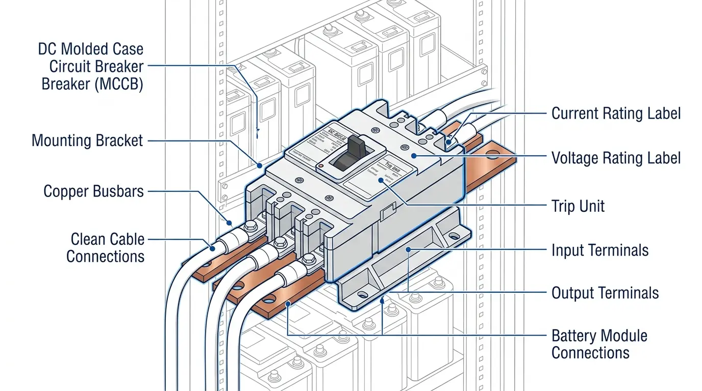
DC molded case circuit breakers become necessary when current exceeds MCB ranges or higher breaking capacity is required:
| Selection Factor | Choose DC MCB | Choose DC MCCB |
|---|---|---|
| Current ≤63 A | ✓ | |
| Current >125 A | ✓ | |
| Breaking capacity >15 kA | ✓ | |
| DIN rail preferred | ✓ | |
| Adjustable trip needed | ✓ |
Proper installation directly impacts breaker performance and longevity. ESS environments present unique challenges that differ from controlled laboratory conditions.
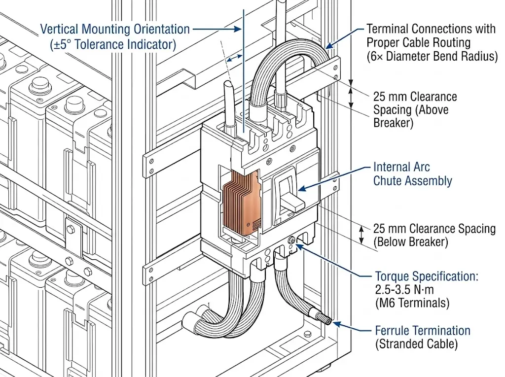
Most DC breakers with magnetic arc blowout systems require vertical mounting (±5° tolerance) to ensure proper arc deflection into chute assemblies. Horizontal mounting may reduce breaking capacity by 10–20% due to altered arc gas flow. Always verify manufacturer specifications for non-vertical installations.
Maintain minimum clearances around breakers for heat dissipation—typically 25 mm above and below, 10 mm between adjacent devices.
Terminal connections require precise torque application to prevent both loose connections (causing resistive heating) and over-tightening (damaging terminal blocks). For typical 100 A DC breakers, terminal torque specifications range from 2.5–3.5 N·m for M6 screws, verified with calibrated torque wrenches. Cable sizing must account for voltage drop limits—generally ≤3% for DC strings—and ampacity derating factors based on installation conditions.
| Wire Size | Terminal Torque |
|---|---|
| 10–16 mm² | 2.5–3.0 N·m |
| 25–35 mm² | 4.0–5.0 N·m |
| 50–70 mm² | 8.0–10.0 N·m |
Use ferrules or properly rated lugs for stranded conductors. Direct insertion of bare stranded wire creates reliability risks under thermal cycling.
Field data from a 10 MWh installation in Guangdong showed container internal temperatures reaching 52°C during peak discharge despite active cooling. Breakers rated at 40°C ambient required derating to 85% of nominal current capacity.
At 50°C ambient, apply approximately 0.9× current derating. At 55°C, apply 0.85×. Consult manufacturer derating curves for precise values specific to your selected breaker model.
[Expert Insight: Field Installation Lessons]
- Verify breaker polarity markings align with system positive/negative before energizing
- Perform insulation resistance testing at 1000 VDC minimum—expect readings above 100 MΩ for new installations
- Document all breaker settings in commissioning records for maintenance reference
- Separate DC power cables from BMS communication wiring by minimum 100 mm
ESS installations expose DC circuit breakers to environmental stresses that directly impact protection reliability.
Container-based ESS systems in desert climates experience internal ambient temperatures reaching 55°C during peak charge cycles. Cold-climate installations may see startup temperatures as low as −40°C. Standard DC circuit breakers are rated for −5°C to +40°C ambient per IEC 60947-2. Enhanced versions for ESS applications extend this to −25°C to +60°C continuous operation.
Humidity tolerance should extend to 95% non-condensing. Field data from a 15 MW solar-plus-storage facility in Guangdong showed that unprotected breakers in 85% RH environments developed surface tracking within 18 months, while properly sealed IP65-rated units maintained insulation resistance above 100 MΩ throughout a 5-year monitoring period.
At elevations above 2000 m, reduced air density diminishes both convective cooling and dielectric strength. Per IEC 60947-1, breaking capacity decreases approximately 1% per 100 m above 2000 m elevation.
In a 20 MWh containerized BESS project in Qinghai Province (2023) at 2800 m altitude, standard DC MCBs experienced 15% reduction in effective breaking capacity. A breaker rated 50 kA Icu at sea level achieves only 42–45 kA at 3000 m. Specify breakers tested for actual installation altitude or apply appropriate derating factors during design.
ESS protection schemes typically combine DC breakers with fuses for comprehensive fault coverage.
Effective battery storage protection uses layered devices:
DC fuses offer extremely fast response to high-magnitude faults—often clearing in under 5 ms. DC breakers provide overload protection with time-delay characteristics, manual isolation capability, and reusability after trip. For fuse selection in battery module protection, the DC Fuse product line includes gPV types rated for 1000–1500 VDC.
Modern ESS installations connect breaker auxiliary contacts to the Battery Management System. Specify breakers with auxiliary contact blocks (minimum 1NO+1NC) and shunt trip coils matching BMS output voltage (commonly 24 VDC or 48 VDC).
BMS-initiated disconnection triggers include cell voltage exceeding safe limits, temperature sensor anomalies, state-of-charge imbalance beyond threshold, and ground fault detection.
DC breakers for ESS must comply with both general low-voltage switchgear standards and energy storage-specific codes.
| Padrão | Scope |
|---|---|
| IEC 60947-2 Annex M | DC-specific performance requirements |
| IEC 62933-5-2 | ESS safety requirements |
| UL 489B | DC circuit breakers (North America) |
| GB/T 14048.2 | Chinese national standard |
Verify certification marks appropriate for your target market: CE (European), CCC (China), UL/cUL (North America), or TÜV (third-party validation). Request type test reports showing DC voltage rating, breaking capacity at specified L/R time constant, and temperature rise data.
For detailed IEC 60947-2 requirements, refer to the official IEC publication.
Battery energy storage represents significant capital investment. The DC circuit breaker serves as the critical safety gateway between stored energy and connected systems.
Selection checklist:
Sinobreaker manufactures DC circuit breakers engineered specifically for energy storage applications, with voltage ratings to 1500 VDC, breaking capacities to 50 kA, and full IEC 60947-2 Annex M compliance. Our technical team provides breaker-fuse coordination analysis and application support for ESS projects from residential to utility scale.
Explore the complete DC Circuit Breaker range for energy storage, solar, and EV charging applications.
Choose a DC circuit breaker rated at minimum 1100–1250 VDC to provide adequate margin above the battery’s maximum charging voltage, which typically reaches 1050–1100 VDC in nominal 1000V systems during equalization charging.
No. AC breakers rely on current zero-crossing for arc extinction, which never occurs in DC circuits. Using AC breakers in battery storage applications risks sustained arcing, contact damage, and failure to clear faults safely.
Above 2000 m elevation, reduced air density decreases both dielectric strength and convective cooling. Breaking capacity typically drops 1% per 100 m above 2000 m, requiring either altitude-rated breakers or appropriate derating during system design.
Commercial ESS systems (100–500 kWh) generally require DC circuit breakers with 25–50 kA breaking capacity to safely interrupt prospective fault currents from low-impedance lithium battery strings operating at 400–800 VDC.
Inspect annually for terminal tightness, contact condition, and proper mechanical operation. High-cycle applications with multiple daily charge-discharge cycles may warrant inspection every 6 months, particularly for breakers approaching rated electrical endurance limits.
Specify minimum 1NO+1NC auxiliary contact block for status monitoring, plus a shunt trip coil (typically 24 VDC or 48 VDC) enabling BMS-initiated emergency disconnection when cell voltage, temperature, or balance thresholds are exceeded.
Plot time-current curves for all series-connected protective devices and verify minimum 0.1 second separation between upstream and downstream device curves across all expected fault current levels. Most manufacturers provide coordination tables or software tools for this analysis.