Endereço
304 North Cardinal
St. Dorchester Center, MA 02124
Horas de trabalho
De segunda a sexta-feira: das 7h às 19h
Fim de semana: 10:00 - 17:00
Endereço
304 North Cardinal
St. Dorchester Center, MA 02124
Horas de trabalho
De segunda a sexta-feira: das 7h às 19h
Fim de semana: 10:00 - 17:00


DC fuse blocks serve as critical connection points in solar photovoltaic systems, providing both overcurrent protection and organized circuit management. Selecting the right fuse block requires understanding terminal ratings, bus configurations, and environmental factors that affect performance. This comprehensive guide covers everything electrical contractors and system designers need to know about specifying DC fuse blocks for reliable solar installations.
Modern solar arrays demand robust protection components that can handle high DC voltages while maintaining safety standards. DC fuse blocks must accommodate string currents, withstand outdoor conditions, and comply with NEC Article 690 requirements for photovoltaic systems.
DC fuse block differ significantly from AC versions due to the unique challenges of direct current interruption. Unlike alternating current which naturally crosses zero twice per cycle, DC current maintains constant flow requiring specialized arc extinction mechanisms. The continuous current flow creates sustained arcing during fault conditions, demanding fuse blocks with enhanced arc interruption capabilities and appropriate voltage ratings.
DC fuse block incorporate specific design features to manage these challenges. Larger contact spacing prevents arc restrikes, ceramic or high-temperature insulation withstands thermal stress, and properly rated terminals handle both normal operating currents and short-circuit conditions safely.
The distinction becomes critical in solar applications where system voltages commonly reach 600V, 1000V, or 1500V DC. Standard AC-rated fuse blocks fail catastrophically at these DC voltage levels due to inadequate arc interruption and insufficient insulation coordination.
A complete DC fuse block assembly consists of several integrated components working together. The base block provides mechanical support and houses the fusing mechanism, while terminal connections offer secure wire attachment points rated for specific conductor sizes. Bus bars distribute current between multiple fuse positions, and covers protect against accidental contact with live parts.
Terminal design significantly impacts installation reliability. Quality fuse blocks feature compression-type terminals that maintain consistent contact pressure, accept multiple conductor sizes without adapters, and provide clear torque specifications for proper installation. Poor terminal design leads to hot spots, voltage drops, and eventual connection failure.
Principais percepções: Terminal temperature rise under load reveals fuse block quality—premium blocks maintain less than 30°C rise at rated current, while inferior products can exceed 50°C, accelerating component degradation.
Selecting appropriate terminal current ratings requires understanding both nominal load current and derating factors that reduce capacity. Solar fuse blocks must handle string currents continuously while accounting for ambient temperature, conductor fill, and enclosure effects that increase operating temperatures.
NEC Section 690.8(A) requires overcurrent devices to be sized at 156% of maximum circuit current. However, the fuse block terminals themselves must accommodate the actual conductor ampacity selected for this increased protection level. A 10A string current requires fuses rated at 15A or 16A, but terminals must handle the conductor sized for this protective device—typically 20A capacity minimum.
| String Current | NEC Required Fuse | Tamanho do condutor | Terminal Rating |
|---|---|---|---|
| 8A | 15A | 14 AWG | 20A minimum |
| 10A | 16A | 12 AWG | 25A minimum |
| 12A | 20A | 12 AWG | 30A minimum |
| 15A | 25A | 10 AWG | 40A minimum |
Temperature derating becomes critical in enclosed combiner boxes where ambient temperatures routinely exceed 40°C. NEC Table 690.31(C) provides correction factors—at 50°C ambient, conductors operate at approximately 82% of their rated capacity. Terminal blocks must account for these reduced ratings to prevent overheating at the connection points.
DC voltage ratings on DC fuse block represent the maximum system voltage the block can safely isolate during fault conditions. This rating must equal or exceed the maximum open-circuit voltage of the PV array under all conditions, including cold temperature voltage rise.
For 1000V DC systems, DC fuse block must carry minimum 1000V DC ratings verified by UL or IEC testing. Some manufacturers list 600V AC ratings but lack appropriate DC certification—these blocks fail catastrophically in high-voltage DC applications due to inadequate creepage and clearance distances between live parts.
The relationship between AC and DC voltage ratings is not linear. A 600V AC rated component may only handle 300-400V DC safely due to the sustained arcing challenges in DC circuits. Always verify explicit DC voltage ratings rather than assuming AC ratings apply.
DC Fuse block bus configuration determines how current flows through the assembly and affects both system protection and installation flexibility. Series bus configurations connect multiple fuse positions in sequence along a common conductor, while parallel bus designs feed each fuse position independently from a main distribution point.
Series bus arrangements work well for string combiner applications where multiple PV strings of similar current ratings converge. Current from each string passes through its protection fuse, then combines on a common positive and negative bus bar running the length of the DC fuse block. This design minimizes wiring complexity and provides clean installation appearance.
Parallel bus configurations offer superior flexibility for mixed current applications or staged system expansions. Each fuse position connects independently to main distribution buses, allowing different fuse ratings and conductor sizes at each position without affecting other circuits. This design suits applications where string currents vary or future capacity additions are planned.

Modular bus systems allow field configuration of fuse block layouts, letting installers add or remove fuse positions as system requirements change. These systems typically use individual fuse holders that snap onto a DIN rail or mounting track, with separate bus bars connecting the assemblies. Modular designs excel in custom applications or retrofit situations where flexibility outweighs the cost premium.
Integrated bus systems combine fuse holders, bus bars, and terminals in a single pre-assembled unit. These blocks offer superior mechanical stability, reduced installation time, and better quality control since critical connections are factory-made rather than field-assembled. Most solar combiner boxes use integrated bus DC fuse block for reliability and code compliance simplicity.
⚠️ Importante: Modular DC fuse block systems require careful attention to bus bar sizing—the bus must handle the sum of all connected fuse ratings, not just the expected load current. Undersized buses create voltage drop and fire hazards.
Terminal block materials directly impact long-term reliability under thermal cycling and environmental exposure. Copper terminals provide excellent conductivity and mechanical strength, making them standard for quality fuse blocks. Some manufacturers use copper-plated aluminum terminals to reduce cost, but these connections require higher torque and more frequent inspection due to aluminum’s tendency to creep under compression.
Brass terminals offer corrosion resistance superior to bare copper in marine or coastal installations, though conductivity drops slightly compared to pure copper. The trade-off often proves worthwhile in harsh environments where corrosion could compromise connections. Terminal plating—typically tin or silver—prevents oxidation and maintains low contact resistance over decades of service.
Insulation materials must withstand both temperature extremes and UV exposure in outdoor installations. High-temperature plastics like polycarbonate or phenolic resin provide excellent insulation properties while maintaining structural integrity across temperature ranges from -40°C to +85°C. Cheap fuse blocks using standard ABS or PVC plastics become brittle in cold weather and may crack during normal handling.
Bus bar material selection balances conductivity, mechanical strength, and cost considerations. Copper bus bars dominate solar applications due to excellent current-carrying capacity and reliable connection characteristics. Bus bar thickness must handle the combined current of all connected circuits with minimal voltage drop and temperature rise.
A general rule sizes bus bars at 1.5-2.0 times the maximum expected current capacity to account for harmonic currents, transients, and thermal derating in enclosed spaces. For a 10-position DC fuse block with 15A fuses, bus bars should handle 150A minimum theoretical load, so practical sizing would be 225-300A capacity to maintain safety margins.
Bus bar surface treatment affects connection reliability over time. Tin-plated copper bus bars resist oxidation while maintaining good conductivity. Bare copper bars eventually develop oxide layers that increase contact resistance, though proper terminal torque usually penetrates this layer. Silver-plated bus bars offer premium performance but add significant cost rarely justified except in critical applications.
NEC Article 690 establishes specific requirements for overcurrent protection and fuse block installations in photovoltaic systems. Section 690.9(B) requires overcurrent devices to be listed for DC operation at the system voltage and current ratings. This means both the fuses and the fuse blocks holding them must carry appropriate UL or third-party certification for DC service.
Section 690.15 addresses disconnecting means and effectively requires fuse blocks to be installed where accessible for inspection and fuse replacement. Fuse blocks mounted inside combiner boxes must allow servicemen to replace fuses safely with the box open, with appropriate warning labels about live parts remaining energized during fuse replacement.
Current path requirements under 690.31 mandate that all current-carrying conductors be supported and protected appropriately. Fuse block terminals must secure conductors to prevent loosening from thermal cycling or mechanical vibration. Terminal screws require specified torque—typically 7-9 lb-in for 12-10 AWG conductors—to ensure reliable long-term connections.
Dica profissional: Document terminal torque values during installation and verify connections after 6-12 months. Thermal cycling can loosen terminals even when initially tightened correctly, and early re-torquing prevents future failures.
UL 2579 covers DC fuse block specifically designed for photovoltaic applications, establishing performance and safety criteria including DC interrupting ratings, temperature limits, and environmental protection levels. Fuse blocks carrying UL 2579 listing have undergone rigorous testing for solar-specific conditions and provide the highest confidence for code compliance.
Some fuse blocks carry UL 1741 listing as part of complete combiner box assemblies. While the fuse block itself may not have individual listing, the tested assembly meets requirements when used as specified by the manufacturer. This approach works well for standardized combiner boxes but limits field modification options.
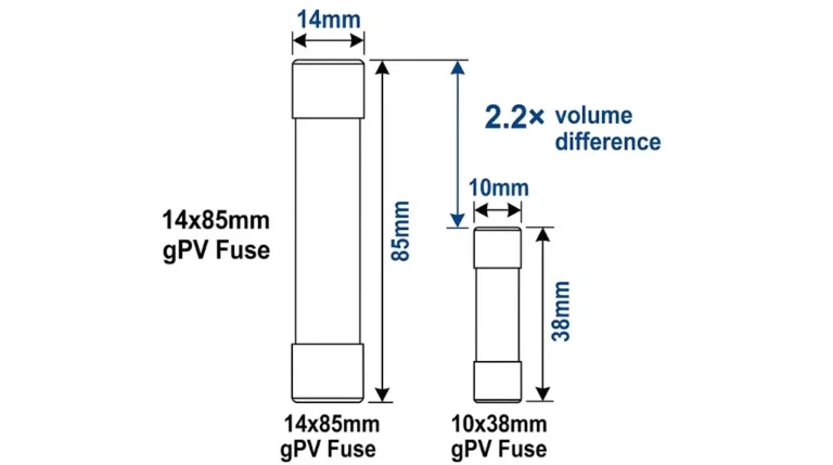
IEC 60269-6 provides international standards for gPV fuse-links and fuse-holders, covering similar ground from a European perspective. Fuse blocks certified to IEC standards often prove more readily available in global markets, though North American installations should verify NEC acceptance in their jurisdiction before specifying IEC-only equipment.

Correct terminal connections ensure reliable fuse block performance throughout system life. Strip conductors to expose only enough bare wire to fill the terminal barrel completely—typically 10-12mm for most terminal blocks. Excessive exposed conductor creates shock hazards, while insufficient insertion reduces contact area and increases resistance.
Insert conductors fully into terminals before tightening, ensuring strands sit flat rather than bunching or twisting. Multi-strand conductors benefit from ferrule end terminations that prevent strand separation and improve contact reliability. Ferrules are mandatory in some jurisdictions and represent best practice even where not required.
Torque terminal screws to manufacturer specifications using a calibrated torque driver or torque wrench. Under-torquing leaves connections loose and prone to heating, while over-torquing damages terminals or strips screws. Most fuse block manufacturers specify 7-9 lb-in for 12-10 AWG conductors, though verify specific requirements for each product.
Apply terminal connections in logical sequence to minimize conductor crossing and maintain clear circuit identification. Typically, all positive conductors terminate on one side of the fuse block with negative returns on the opposite side, creating clear visual separation for troubleshooting and inspection. Label each connection point with circuit identifiers matching system documentation.
Bus bars require secure mechanical support to prevent vibration-induced failures and maintain proper alignment with terminals. Most fuse blocks incorporate integral bus bar mounting, but field-assembled modular systems need careful attention to support spacing and fixation methods. Support bus bars at intervals not exceeding 300mm to prevent flexing under normal handling and conductor weight.
Clean bus bar surfaces before making terminal connections—remove any oxidation, dirt, or protective coatings at connection points. Apply joint compound to bare copper bus bars if specified by the manufacturer, though tin-plated bars typically need no treatment. Ensure connection hardware makes firm contact with bus bar surfaces rather than balancing on edges or corners.
Bus bar joints and splices represent potential failure points requiring special attention. Overlap joints should provide at least 40mm of contact surface with multiple fasteners distributing mechanical and electrical loads. Avoid single-bolt splices that concentrate stress and current flow in small areas prone to overheating.
⚠️ Importante: Thermal expansion causes bus bars to shift with temperature changes. Allow slight clearance at fixed mounting points to accommodate expansion without stressing connections or cracking insulation.
IP (Ingress Protection) ratings define fuse block resistance to dust and water ingress, critical for outdoor solar installations. Indoor fuse blocks may require only IP20 protection (finger-safe, no water protection), while outdoor combiner boxes typically need IP65 (dust-tight, water jet resistant) or IP66 (dust-tight, powerful water jet resistant) ratings.
The IP rating applies to the complete assembly including fuse block, enclosure, and all cover connections. A high IP-rated fuse block installed in a poorly sealed enclosure provides no better protection than the weakest element. Verify that fuse block designs allow proper gasket seating and cover engagement to maintain enclosure ratings.
Coastal installations face additional challenges from salt spray and fog. IP ratings alone don’t address corrosion resistance—specify fuse blocks with enhanced plating and coatings in marine environments. Stainless steel hardware and tin-plated copper components significantly improve longevity compared to standard materials in corrosive atmospheres.
Fuse blocks must function across temperature ranges encountered in outdoor installations, typically -40°C to +85°C for solar applications. Cold temperature affects plastic mechanical properties, while high temperatures accelerate material aging and increase conductor resistance. Quality fuse blocks specify performance across their entire temperature range rather than at arbitrary test conditions.
Enclosed combiner boxes amplify solar heating, creating internal temperatures 20-30°C above ambient in direct sunlight. Dark-colored enclosures in desert climates can reach 80°C internally even when air temperature is only 45°C. Fuse block selection must account for these extreme conditions to prevent softening plastics, melting insulation, or exceeding terminal temperature ratings.
Ventilation strategies improve thermal conditions inside combiner boxes. Ventilated designs with screened openings allow convective cooling while maintaining moisture protection. However, ventilation admits dust and insects, requiring careful balance between thermal and environmental protection needs. Sealed boxes run hotter but exclude contaminants more effectively.
Problema: Installing fuse blocks with terminal ratings lower than the conductor ampacity they must accommodate.
Cenários comuns:
– Using 20A terminals for circuits requiring 12 AWG conductors rated at 25A
– Failing to account for NEC 156% fuse sizing requirement in terminal selection
– Ignoring temperature derating effects that reduce effective terminal capacity
Correção: Select terminal ratings at least 125% of the maximum expected conductor ampacity after all derating factors. For a string requiring 15A protection, minimum terminal rating should be 25-30A to accommodate the conductor sized for 15A overcurrent protection plus safety margin.
Problema: Using AC-rated fuse blocks in DC applications without verifying DC suitability.
Cenários comuns:
– Assuming 600V AC rating equals 600V DC capability
– Installing standard industrial fuse blocks in solar combiners
– Failing to recognize that most electrical components default to AC ratings
Correção: Verify explicit DC voltage ratings on all fuse block components. Look for UL 2579 or IEC 60269-6 certification specifically covering photovoltaic applications. When in doubt, contact manufacturers for DC rating confirmation rather than assuming AC specifications apply.
Problema: Installing bus bars with insufficient current capacity for the total connected load.
Cenários comuns:
– Sizing bus bars for expected load without accounting for maximum possible current from all fuses
– Failing to derate bus bars for elevated enclosure temperatures
– Using single-position fuse holder bus bars when combining multiple strings
Correção: Size bus bars at 150-200% of the sum of all connected fuse ratings, accounting for elevated temperatures inside enclosed spaces. A fuse block with six 15A positions requires bus bars rated for 135-180A minimum, even if expected load is lower.
Problema: Under-tightening or over-tightening terminal connections during installation.
Cenários comuns:
– Tightening terminals by feel without calibrated tools
– Using impact drivers that exceed torque specifications
– Failing to verify connections after thermal cycling
Correção: Use calibrated torque drivers set to manufacturer specifications—typically 7-9 lb-in for 12-10 AWG conductors. Document torque values during installation and plan re-inspection after 6-12 months of operation to catch any loosening from thermal cycling.

Regular fuse block inspection prevents failures and maintains system reliability. Visual inspections every 6 months identify obvious issues like cracked insulation, discolored terminals suggesting overheating, or loose mounting hardware. Annual detailed inspections include thermal imaging to detect hot spots invisible during visual examination.
Check terminal connections for tightness using the torque wrench set to original installation specifications. Connections naturally loosen over time from thermal cycling—temperature changes cause conductors and terminals to expand and contract at different rates, gradually reducing contact pressure. Re-torquing during the first year after installation prevents this loosening from developing into failures.
Inspect fuse contacts for signs of arcing or burning, indicating either fuse deterioration or overcurrent events. Darkened fuse ends or discolored fuse holders suggest problems requiring investigation. Replace any fuses showing damage even if not blown—degraded fuses may fail to protect properly or introduce unwanted resistance in the circuit.
Clean fuse block assemblies to remove dust and debris accumulation that can create tracking paths for current or attract moisture. Use dry compressed air or soft brushes to avoid damaging insulation or disturbing connections. Never use solvents on fuse blocks unless specifically approved by the manufacturer—many chemicals attack plastic materials.
Infrared thermal imaging reveals connection problems before they cause failures. Hot spots at terminals indicate high resistance from loose connections, corroded conductors, or undersized components. Temperature differences exceeding 10°C between similar connection points warrant immediate investigation.
Conduct thermal imaging under load conditions—unloaded connections appear normal even when degraded. Schedule imaging during peak production hours when maximum current flows through fuse blocks. For string combiner applications, this typically occurs during midday clear sky conditions when array output peaks.
Establish baseline thermal images during commissioning for future comparison. Connection temperatures naturally vary based on load current and ambient conditions, making absolute temperature values less meaningful than relative changes over time. A terminal running 35°C when new but 50°C a year later indicates developing problems even though neither temperature represents immediate danger.
Document thermal images with clear labeling of circuit identifiers and measurement points. Include ambient temperature and load current data with each image set. Trending this data over years reveals patterns indicating when preventive maintenance or component replacement becomes necessary before failures occur.
Large solar arrays require coordination between string fuses in combiner boxes and upstream breakers protecting main DC circuits. Proper coordination ensures faults clear at the appropriate level without causing unnecessary downtime or damage to healthy circuits. Fuse blocks must accommodate the selected fuse ratings while allowing coordination with system protection scheme.
Review time-current curves for all protective devices in the current path from PV strings to inverter. String fuses should clear before upstream breakers operate, isolating faults to the affected string only. This requires selecting fuses with faster clearing times than upstream devices at expected fault current levels.
Coordination becomes more complex in systems using multiple combiner tiers—string combiners feeding array combiners feeding main DC combiners. Each tier needs progressively slower protective devices allowing downstream protection to operate first. Fuse block terminal ratings must accommodate the larger conductors required at each successive tier.
Systems operating at 1000V DC or higher impose additional requirements on fuse block selection and installation. Creepage and clearance distances increase substantially—IEC 60664-1 specifies minimum spacing based on pollution degree and overvoltage category. Standard fuse blocks designed for 600V or 1000V applications may not provide adequate spacing for 1500V systems.
High-voltage fuse blocks typically feature extended terminal spacing, enhanced insulation coordination, and specialized covers preventing accidental contact with live parts. Some designs incorporate barriers between adjacent terminals creating dedicated compartments for each circuit, preventing arc-over between positions during fault conditions.
Installation requirements for high-voltage fuse blocks include enhanced warning labels, restricted access provisions, and documentation of qualified worker requirements. NEC 690.35 requires readily accessible disconnecting means, but high-voltage equipment may need additional access controls preventing unqualified persons from opening enclosures containing energized parts.
Residential solar installations typically use 6-12 string systems at 400-600V DC. Fuse blocks for these applications prioritize compact size, simple installation, and reliable protection without excessive cost. Standard fuse blocks rated 600V DC with 20-30A terminals accommodate most residential string configurations efficiently.
Look for integrated assemblies that simplify combiner box assembly and reduce field wiring. Residential installers benefit from fuse blocks with clear terminal labeling, obvious fuse orientation indicators, and foolproof mounting that prevents improper installation. DIN rail mounted blocks work well for residential applications where panel space efficiency matters.
Consider future expansion when selecting residential fuse blocks. Systems installed with 8 strings but fuse blocks accommodating 12 positions allow later additions without replacing the entire combiner assembly. The modest cost difference between 8 and 12 position blocks often proves worthwhile compared to complete combiner replacement during expansions.
Commercial installations commonly operate at 1000V DC to maximize string length and reduce current levels. Fuse blocks for commercial applications must meet more stringent voltage ratings while handling higher string counts—16-24 string combiners are typical. Modular designs allowing field configuration suit varied commercial system layouts.
Commercial fuse blocks benefit from enhanced monitoring capabilities. Some designs incorporate fuse status indicators showing which fuses have operated without requiring enclosure access. Others integrate with building management systems providing remote monitoring and alert generation when fuses operate or connections overheat.
Maintenance accessibility becomes more critical in commercial installations where multiple contractors may service the system over its lifetime. Select fuse blocks with clear labeling, standard fuse types widely available, and detailed documentation including torque specifications, replacement procedures, and troubleshooting guidance. These features reduce service costs and minimize downtime during maintenance events.
Utility-scale solar farms operating at 1500V DC require premium fuse blocks meeting the highest voltage and reliability standards. These massive installations combine hundreds or thousands of strings, making fuse block reliability critical to overall system availability. Component failures affecting even small percentages of strings significantly impact revenue.
Specify fuse blocks with proven track records in harsh environments and extensive third-party testing verification. UL 2579 listing proves essential, with additional qualification testing under extreme temperature, humidity, and vibration conditions. Review manufacturer field failure data and warranty terms—utility-scale components should offer 10+ year performance warranties covering both materials and labor.
Utility-scale fuse blocks increasingly incorporate smart features including individual string monitoring, arc fault detection, and predictive maintenance algorithms identifying degrading components before failures occur. While these advanced blocks cost more initially, the improved availability and reduced maintenance costs justify the investment in multi-megawatt installations.
DC fuse blocks differ from AC versions in voltage ratings, arc interruption capabilities, and contact spacing. DC current creates sustained arcing during interruption since it doesn’t naturally cross zero like AC current. DC-rated fuse blocks incorporate larger contact gaps, enhanced arc chutes, and specialized materials to safely interrupt DC faults. A 600V AC fuse block may only handle 300-400V DC safely. Always verify explicit DC voltage ratings rather than assuming AC-rated components work for DC applications.
Terminal ratings should be at least 125% of the maximum conductor ampacity required for your circuit after applying all NEC requirements and derating factors. For solar applications, calculate string current, multiply by 156% per NEC 690.8(A) to determine fuse rating, then size conductors for that fuse. Select terminal ratings exceeding the conductor ampacity—if 12 AWG conductors (25A capacity) are required, specify terminals rated 30A minimum. This provides margin for thermal derating in enclosed spaces and accounts for installation conditions.
Yes, when using parallel bus configurations where each position connects independently to distribution buses. Different circuits may require different protection levels based on conductor size and equipment ratings. Series bus configurations work best with uniform fuse ratings since all positions carry combined current from upstream positions. Check manufacturer specifications—some fuse blocks list maximum mixed ratings, and the bus bars must handle the sum of all fuse ratings regardless of expected load current.
Outdoor solar installations typically require IP65 (dust-tight, water jet resistant) or IP66 (dust-tight, powerful water jet resistant) ratings for fuse blocks inside combiner boxes. The IP rating applies to the complete assembly including enclosure, covers, and cable entries—not just the fuse block alone. Coastal or marine environments benefit from IP66 or IP67 ratings providing additional protection against salt spray and moisture ingress. Indoor installations may require only IP20 (finger-safe) protection, though enclosed panels benefit from higher ratings preventing dust accumulation.
Re-torque fuse block terminals after 6-12 months of initial operation, then annually or per manufacturer recommendations. Thermal cycling causes gradual loosening even when terminals are initially torqued correctly—temperature changes make conductors and terminals expand and contract at different rates, reducing contact pressure over time. Document torque values during initial installation and all subsequent maintenance. Thermal imaging provides early warning of developing connection problems between scheduled re-torquing—hot spots indicate immediate attention is needed regardless of maintenance schedule.
Terminal discoloration indicates excessive heat from high resistance connections. Common causes include insufficient tightening torque, corroded conductors, undersized terminals for the conductor ampacity, or loose bus bar connections. Brown or black discoloration represents oxidation from moderate overheating, while melted or deformed plastic indicates severe overheating requiring immediate replacement. Investigate and correct the root cause before putting the fuse block back in service—simply replacing the block without addressing why it overheated leads to repeated failures.
Yes, proper installation requires a calibrated torque driver or torque wrench set to manufacturer specifications—typically 7-9 lb-in for 12-10 AWG conductors. Standard screwdrivers cannot reliably achieve correct torque, leading to either loose connections that overheat or over-tightened terminals that damage components. Wire strippers, ferrule crimping tools for stranded conductors, and appropriate labeling equipment are also necessary. Budget for proper installation tools as part of system costs—the tools pay for themselves by preventing connection failures requiring troubleshooting and rework.
Proper DC fuse block selection represents just one element of comprehensive photovoltaic system protection. Understanding how fuse blocks integrate with other protective components ensures reliable solar installations meeting all code requirements.
Learn more about related protective devices in our comprehensive guides:
- DC Fuses for Solar Systems – Complete guide to gPV fuse selection, ratings, and coordination
- Disjuntores solares CC – Alternative protection methods using resettable circuit breakers
- Projeto da caixa combinadora fotovoltaica – Complete combiner box specification including fuse block integration
- DC SPD Protection – Surge protection devices working with fuse blocks for lightning protection
Ready to specify compliant DC fuse blocks for your solar installation? Our technical team at SYNODE provides project-specific recommendations based on your system voltage, string configuration, and environmental conditions. We help ensure proper terminal ratings, bus sizing, and NEC compliance for reliable photovoltaic protection systems.
Contact our application engineers for fuse block selection assistance and integration guidance for projects from residential to utility-scale.
Última atualização: Outubro de 2025
Autor: Equipe técnica do SYNODE
Avaliado por: Departamento de Engenharia Elétrica