Adresse
304 Nord Kardinal
St. Dorchester Center, MA 02124
Arbeitszeiten
Montag bis Freitag: 7AM - 7PM
Am Wochenende: 10AM - 5PM
Adresse
304 Nord Kardinal
St. Dorchester Center, MA 02124
Arbeitszeiten
Montag bis Freitag: 7AM - 7PM
Am Wochenende: 10AM - 5PM

Ein 48-V-Gleichstrom-Leistungsschalter dient als primäre Überstromschutzvorrichtung in Telekommunikationssystemen und Verteilungsnetzen von Rechenzentren und unterbricht Fehlerströme ohne den natürlichen Vorteil des Nulldurchgangs, den Wechselstromsysteme bieten. Im Gegensatz zu Wechselstromkreisen, in denen der Strom 100-120 Mal pro Sekunde den Nullpunkt durchbricht, fließen Gleichstromfehlerströme kontinuierlich und erzeugen anhaltende Lichtbögen, die von Standard-AC-Schaltern nicht zuverlässig gelöscht werden können.
Im Rahmen eines Nachrüstungsprojekts für 12 Telekommunikations-Basisstationen in der Provinz Guangdong im Jahr 2023 wurde die Umstellung von 32-A-Sicherungen auf ordnungsgemäße 48V DC-MCBs reduzierte die durchschnittliche Zeit bis zur Wiederherstellung des Betriebs von 3,2 Stunden auf 18 Minuten pro Fehlerereignis. Dieser Leistungsunterschied verdeutlicht, warum die Auswahl von Leistungsschaltern in unternehmenskritischen Umgebungen wichtig ist.
Gemäß IEC 60947-2 Anhang H muss ein gleichstromtauglicher Schalter ein Ausschaltvermögen bei seiner Nenngleichspannung aufweisen, wobei die Lichtbogenenergie vollständig im Gehäuse enthalten sein muss. Für Systeme mit 48 V Nennspannung - die in Telekom-Gleichrichterkonfigurationen 57,6 V Erhaltungsspannung erreichen können - müssen Schalter diese erhöhte Spannung bewältigen und gleichzeitig das Nennausschaltvermögen beibehalten, typischerweise 6 kA bis 10 kA für Geräte auf Verteilungsebene.
Die Physik ist ganz einfach. Wenn sich Kontakte unter Fehlerbedingungen trennen, bildet sich ein Lichtbogen über der Lücke. Bei 48 V Nennspannung (typischerweise 42-60 V Betriebsbereich) muss die Lichtbogenspannung die Systemspannung übersteigen, um eine Stromunterbrechung zu erzwingen. Der Lichtbogen erzeugt an der Kontaktoberfläche Temperaturen von 3000-5000°C. Eine niedrigere Spannung bedeutet, dass der Lichtbogen leichter bestehen bleibt, was aggressive Unterbrechungsmechanismen erfordert, die bei AC-Schaltern einfach fehlen.
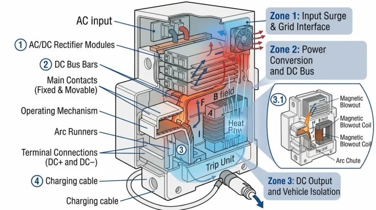
Moderne 48-V-Gleichstromunterbrecher verwenden magnetische Blasspulen, die eine Feldstärke von 30-80 mT erzeugen, um den Lichtbogen in segmentierte Lichtbogenschächte abzulenken. Jede Stahl- oder Keramikplatte in der Lichtbogenkammer zwingt den Lichtbogen dazu, über mehrere Lücken hinweg erneut zu zünden, wodurch sich die Lichtbogenspannungsabfälle vervielfachen. Ein typisches Design verwendet 8-12 Lichtbogenschachtplatten, die zusammen die Lichtbogenspannung auf 80-120 V erhöhen - weit über die 48-V-Systemspannung - und so eine zuverlässige Löschung innerhalb von 5-15 Millisekunden bei Fehlern bis zu 10 kA gewährleisten.
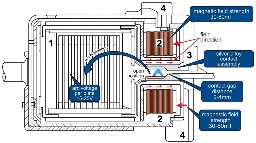
[Experteneinblick: DC-Bogenunterbrechung]
- Kontakttrenngeschwindigkeit bei Qualitätshämmern: 1,5-3,0 m/s
- Jede Verteilerplatte erhöht die Lichtbogenspannung um etwa 15-25 V
- Keramisch gefüllte Lichtbogenschächte reduzieren die Lichtbogendauer von 15-20 ms auf 8-12 ms im Vergleich zu polymeren Alternativen
- Silber-Wolfram (AgW)-Kontakte halten mehr als 4000 Betätigungen bei Nennstrom aus, bevor sie ausgetauscht werden müssen
Die Auswahl des richtigen 48-V-DC-Leistungsschalters erfordert die Abstimmung dreier voneinander abhängiger Parameter: Nennspannung (Ue), Nennstrom (In) und Nenn-Kurzschlussausschaltvermögen (Icu).
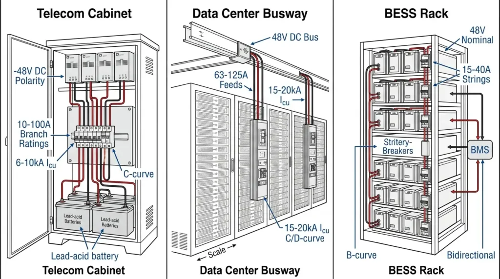
Telekommunikationsanwendungen, die der Norm ETSI EN 300 132-2 entsprechen, arbeiten mit -48V DC (positive Erdung) und erfordern Schalter mit polaritätssensitiven Lichtbogenschachtdesigns. 48-V-Bus-Architekturen in Rechenzentren erfordern Leistungsschalter, die für einen bidirektionalen Stromfluss ausgelegt sind, um Batterielade-/Entladezyklen von bis zu 200 A kontinuierlich pro Strang zu ermöglichen.
Telekommunikationszweigstromkreise reichen in der Regel von 10 A bis 100 A pro Stromkreis. Die Einspeisung in Rechenzentren erfordert häufig Nennströme von 63A bis 125A. Berücksichtigen Sie immer den Dauerbetrieb - Leistungsschalter sollten nicht mehr als 80% des Nennstroms für anhaltende Lasten in geschlossenen Schalttafeln mit begrenzter Wärmeabgabe liefern.
Das Ausschaltvermögen muss den prospektiven Fehlerstrom am Installationspunkt übersteigen. Eine typische Telekom-Stromverteilungsanlage, die von 100-Ah-Batteriebänken gespeist wird, kann innerhalb der ersten 5 Millisekunden einen prospektiven Fehlerstrom von 8-12 kA liefern. Sammelschienenverteilersysteme in Rechenzentren können 15 kA überschreiten. Wählen Sie Schalter mit einem Icu-Wert von mindestens 10 kA bei 60 V DC für Telekommunikationsanwendungen; 20 kA oder höher für Sammelschieneninstallationen in Rechenzentren gemäß der Industrienorm IEC 60947-2.
Die Auslösecharakteristiken bestimmen die Reaktion auf verschiedene Fehlertypen:
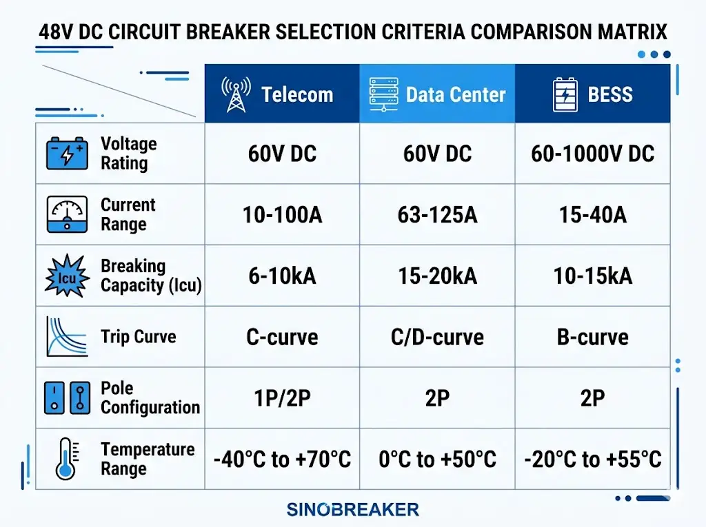
Telekommunikationsschränke für den Außenbereich erfordern Leistungsschalter, die für Umgebungsbedingungen von -40°C bis +70°C ausgelegt sind. Der entscheidende Auswahlparameter ist das DC-Ausschaltvermögen - typischerweise 6 kA bis 10 kA gemäß IEC 60898-2-Anforderungen für den Geräteschutz. Negative Erdungspolarität (-48V DC) ist Standard; stellen Sie sicher, dass die Ausrichtung des Lichtbogenschachts des Schalters mit der Polarität der Installation übereinstimmt.
Hyperscale-Einrichtungen, die Open Compute Project-Architekturen einsetzen, verwenden zunehmend eine 48-V-Gleichstromverteilung, um AC-DC-Wandlungsverluste zu vermeiden. Die Auswahlpriorität verlagert sich auf die Strombegrenzungsfähigkeit: Schalter, die die Durchlassenergie (I²t) begrenzen, schützen die nachgeschalteten Sammelschienen und Batterieanschlüsse vor thermischen Schäden bei verschraubten Fehlern.
Bei einer Nachrüstung eines Tier-III-Rechenzentrums in Frankfurt (480 Serverschränke) im Jahr 2023 wird von 32 A auf 63 A aufgerüstet. DC-MCBs mit 10 kA Ausschaltvermögen reduzierte die störenden Auslösungen bei Spitzenlasttransienten um 78%, wobei der Fehlerabstand unter 8 ms blieb.
Bei 48-V-BESS-Installationen muss der DC-Schutzschalter einen bidirektionalen Stromfluss während der Lade-/Entladezyklen bewältigen. Für den Schutz auf Stringebene sind in der Regel Nennwerte von 15A bis 40A mit B-Kurvencharakteristik erforderlich. Der entscheidende Unterschied zur Telekommunikation: BESS-Schutzschalter müssen Fehlerströme von netz- und batterieseitigen Quellen gleichzeitig unterbrechen.
[Expert Insight: Kurzreferenz zur Anwendungsauswahl]
- Telekommunikation: C-Kurve, 6-10 kA Icu, Nenntemperatur -40°C bis +70°C, polaritätsempfindlich
- Rechenzentrum: C-Kurve oder D-Kurve, 15-20 kA Icu, strombegrenzend bevorzugt
- BESS: B-Kurve, bidirektional ausgelegt, Koordination mit Batteriemanagementsystem
- Alle Anwendungen: Gleichspannungsangaben auf dem Typenschild prüfen - Wechselspannungsangaben gelten nicht
Eine ordnungsgemäße Koordinierung gewährleistet eine selektive Auslösung - der dem Fehler am nächsten liegende Schalter öffnet zuerst und minimiert so die Systemunterbrechung. In 48-V-DC-Systemen mit mehreren Schutzstufen verhindert die Zeit-Strom-Kurvenanalyse sowohl Fehlauslösungen als auch blinde Flecken im Schutz.
Hauptverteilerschalter sollten höhere Nennströme und langsamere Auslösekennlinien als Abzweigschalter haben. Ein 125-A-Hauptschalter mit D-Kurven-Charakteristik koordiniert sich gut mit 32-A-Abzweigschaltern mit C-Kurven-Charakteristik und bietet mindestens 0,1 Sekunden Abstand bei maximalem Fehlerstrom.
Viele Telekommunikationsanlagen verwenden DC-Sicherungen an den Batterieklemmen mit nachgeschalteten Unterbrechern für den Abzweigschutz. Die I²t-Durchlasszeit der Sicherung muss die I²t-Beständigkeit des Unterbrechers übersteigen, um sicherzustellen, dass der Unterbrecher auslöst, bevor die Sicherung bei Abzweigfehlern durchbrennt, während die Sicherung batterieseitige Fehler löscht, die die Kapazität des Unterbrechers überschreiten.
Moderne Lithiumbatteriesysteme verfügen über einen internen Schutz, der mit externen Unterbrechern koordiniert werden muss. Das BMS reagiert in der Regel innerhalb von 10-50 ms auf Fehler auf Zellebene. Externe Unterbrecher bieten Backup-Schutz und Wartungsisolierung - wählen Sie Auslösezeiten, die eine Reaktion des BMS auf kleinere Fehler ermöglichen, während der Unterbrecher bei anhaltenden Überströmen eingreift.
DIN-Schienenmontage (35 mm) ist Standard für DC-Verteilertafeln sowohl in Telekommunikations- als auch in Rechenzentrumsanwendungen. Ziehen Sie die Klemmenanschlüsse mit dem vom Hersteller angegebenen Drehmoment an - normalerweise 2,0-2,5 Nm für 10-32A-Schalter, 2,5-3,5 Nm für 40-125A-Geräte. Zu schwach angezogene Anschlüsse führen zu Widerstandserwärmung; zu stark angezogene Anschlüsse beschädigen die Klemmen und verringern die Kontaktzuverlässigkeit.
Die Umgebungstemperatur beeinflusst die Leistung des Schalters erheblich. Bei einer Umgebungstemperatur von 50°C (üblich in geschlossenen Telekommunikationsschränken) muss die Strombelastbarkeit um 15-20% reduziert werden. In Höhen über 2000 m muss die Schaltleistung um 1% pro 100 m reduziert werden, da die geringere Luftdichte die Lichtbogenlöschung beeinträchtigt.
Gleichstromsysteme erfordern eine eindeutige Polaritätskennzeichnung. Standardkonvention: rot für Plus, blau oder schwarz für Minus, grün/gelb für Schutzerde. Kennzeichnen Sie jeden Unterbrecher mit der Stromkreisbezeichnung und dem Nennstrom. Bei -48-V-Telekommunikationssystemen ist die positive Erdungskonfiguration deutlich zu kennzeichnen, um Installationsfehler zu vermeiden.
Fünf Fehler sind für die meisten Ausfälle von 48-V-DC-Schaltern in der Praxis verantwortlich:
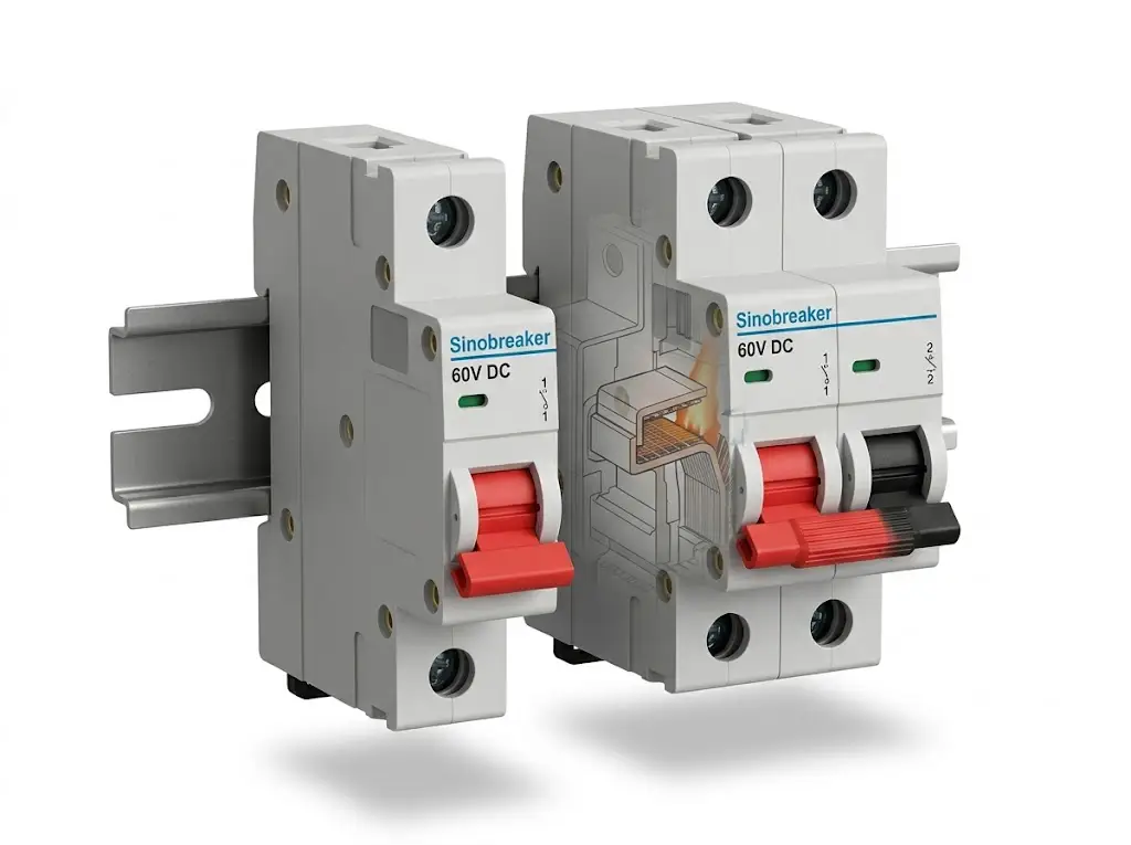
Sinobreaker's DC-Schutzschalter Portfolio deckt die gesamte Bandbreite der Anforderungen von Telekommunikations- und Rechenzentren ab. Die DC-MCB-Reihe bietet Nennwerte von 1 A bis 125 A mit einem Ausschaltvermögen von bis zu 10 kA bei 60 V DC und eignet sich für den Schutz von Zweigstromkreisen in beiden Anwendungen.
Die wichtigsten Spezifikationen für 48-V-Anwendungen:
Für eine projektspezifische Auswahlhilfe wenden Sie sich bitte an das technische Team von Sinobreaker und geben Sie Ihre Systemspannung, den maximalen Fehlerstrom, den Umgebungstemperaturbereich und die Koordinierungsanforderungen an.
Nein. AC-Unterbrecher sind auf den Nulldurchgang des Stroms angewiesen, um Lichtbögen zu löschen, was in DC-Stromkreisen nicht der Fall ist. Der Einsatz eines Wechselstromunterbrechers bei Gleichstrom kann unabhängig von der Nennspannung zu anhaltenden Lichtbögen, Bränden oder Explosionen bei Fehlern führen.
Die meisten Telekom-Installationen erfordern 6-10 kA Schaltleistung bei 60 V DC. Berechnen Sie den voraussichtlichen Fehlerstrom auf der Grundlage der Kapazität der Batteriebank - eine 100-Ah-Bleisäurebank liefert normalerweise 8-12 kA; Lithiumbatterien können 15 kA überschreiten.
Unterbrecher in geschlossenen Schränken bei 50°C Umgebungstemperatur sollten um 15-20% vom Nennstrom des Typenschilds herabgesetzt werden. Ein 63A-Unterbrecher bietet bei erhöhten Temperaturen effektiv 50-54A Dauerleistung.
B-Kurven-Schalter lösen magnetisch beim 3-5-fachen des Nennstroms aus und bieten eine schnellere Reaktion bei ohmschen Lasten und Batteriestromkreisen. C-Kurven-Schalter lösen beim 5-10-fachen des Nennstroms aus und sind besser für Einschaltstromstöße von Gleichrichtern und Netzteilen geeignet.
Einpolige Unterbrecher reichen für Abzweigstromkreise aus, bei denen nur der nicht geerdete Leiter unterbrochen werden muss. Verwenden Sie 2-polige Unterbrecher für Batterietrennschalter, Wartungstrennstellen und alle Stromkreise, die eine gleichzeitige Unterbrechung beider Leiter erfordern.
Der I²t-Durchlasswert der Sicherung muss den I²t-Widerstandswert des nachgeschalteten Unterbrechers übersteigen. Dadurch wird sichergestellt, dass Abzweigfehler den Schalter auslösen, während Fehler, die die Kapazität des Schalters überschreiten, die Sicherung passieren, ohne den Schalter zu beschädigen.