Adresse
304 Nord Kardinal
St. Dorchester Center, MA 02124
Arbeitszeiten
Montag bis Freitag: 7AM - 7PM
Am Wochenende: 10AM - 5PM
Adresse
304 Nord Kardinal
St. Dorchester Center, MA 02124
Arbeitszeiten
Montag bis Freitag: 7AM - 7PM
Am Wochenende: 10AM - 5PM

Die Auswahl des richtigen PV-Sicherungshalters entscheidet darüber, ob Ihr Photovoltaik-Schutzsystem während seiner 25-jährigen Lebensdauer zuverlässig funktioniert oder unter thermischer Belastung vorzeitig ausfällt. Ein PV-Sicherungshalter muss drei kritischen Parametern entsprechen: der Spannungsnennwert entspricht oder übersteigt die System-Voc, der Stromnennwert entspricht oder übersteigt den Sicherungs-In und die physischen Abmessungen entsprechen der Sicherungsgröße - typischerweise 10×38mm oder 14×51mm für Solaranwendungen.
Bei einer 12-MW-Aufdachanlage in der Provinz Jiangsu (2023) verursachte die unsachgemäße Auswahl der Sicherungshalter innerhalb von 18 Monaten 23 Strangausfälle. Jeder Halter war nur für 1000 VDC ausgelegt, während das System mit 1100 VDC nominal betrieben wurde. Die Kosten für den Austausch beliefen sich auf mehr als 180.000 ¥, Produktionsverluste nicht eingerechnet.
Im Gegensatz zu herkömmlichen Wechselstromanwendungen sind die Sicherungshalter bei Photovoltaikanlagen besonderen Belastungen ausgesetzt: kontinuierlicher Gleichstromfluss, Rückstrom von parallelen Strings bei Fehlern und extreme Temperaturschwankungen von -40°C bis +85°C Umgebungstemperatur. Die DC-Spannungsnennwerte der Halter unterscheiden sich grundlegend von den AC-Nennwerten, da DC-Lichtbögen bei Stromnulldurchgängen nicht von selbst verlöschen. Eine Halterung mit einer Nennspannung von 1000 VAC ist möglicherweise nur für 600 VDC geeignet - überprüfen Sie immer die spezifische Gleichspannungsspezifikation.
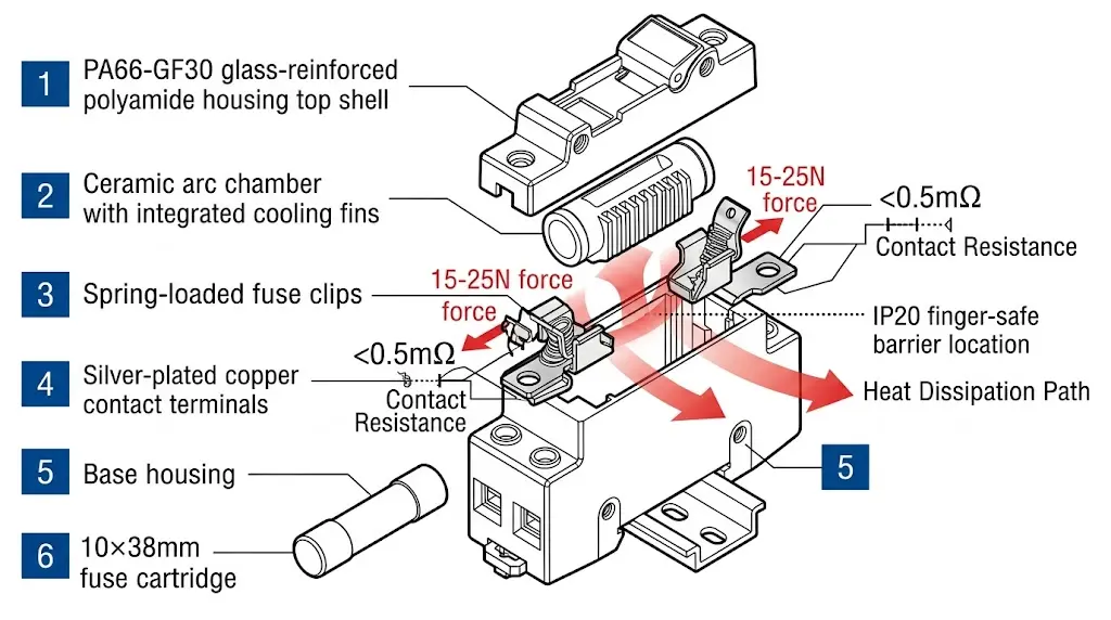
Ein PV-Sicherungshalter besteht aus vier Hauptkomponenten: dem Grundgehäuse, den Kontaktklemmen, den Sicherungsclips und der Lichtbogenlöschkammer. Für das Grundgehäuse wird in der Regel glasfaserverstärktes Polyamid (PA66-GF30) verwendet, das für einen Dauerbetrieb bei 125 °C ausgelegt ist und sowohl mechanische Festigkeit als auch Flammfestigkeit gemäß den Anforderungen der UL 94 V-0 bietet. Die Kontaktanschlüsse werden aus einer versilberten Kupferlegierung hergestellt, um den Kontaktwiderstand auf unter 0,5 mΩ zu minimieren und die Wärmeentwicklung im Normalbetrieb zu verringern.
Die Sicherungsklemmen üben einen Federdruck von 15-25 N aus, um einen gleichmäßigen elektrischen Kontakt über Temperaturschwankungen hinweg zu gewährleisten. Die Wärmebildaufnahmen in der Jiangsu-Installation zeigten, dass Halter mit unzureichender Federspannung bei einem Nennstrom von nur 70% Hot Spots von über 90 °C entwickelten - ein Beweis dafür, warum sich das Design der Klemmen direkt auf die Zuverlässigkeit des Systems auswirkt.
Wenn ein gPV-Sicherungselement unter Fehlerbedingungen schmilzt, muss der Halter den entstehenden Gleichstromlichtbogen eindämmen und erlöschen lassen. Gemäß IEC 60269-6 (Niederspannungssicherungen für photovoltaische Anwendungen) müssen PV-Sicherungshalter eine Lichtbogenspannung aufweisen, die der Systemspannung entspricht oder diese übersteigt, um eine anhaltende Lichtbogenbildung zu verhindern. In der Lichtbogenkammer werden Keramik- oder Melaminbarrieren verwendet, die die Lichtbogenenergie absorbieren und die ionisierten Gase unter die für die Aufrechterhaltung der Leitfähigkeit erforderliche Schwelle von 3000 °C abkühlen.
Die Gleichung für das Ausschaltvermögen bestimmt die Auswahl des Sicherungshalters: Icu ≥ Isc × 1,25, wobei Icu steht für das Nennausschaltvermögen und Isc ist der maximale voraussichtliche Kurzschlussstrom an der Einbaustelle.
Für PV-Installationen im Freien benötigen Sicherungshalter einen Schutzgrad von IP65 oder höher, um das Eindringen von Feuchtigkeit und Staub zu verhindern. Berührungssichere Konstruktionen, die den Anforderungen der IEC 60529 für Fingersicherheit entsprechen (mindestens IP2X), schützen das Wartungspersonal vor versehentlichem Kontakt mit stromführenden Komponenten während der Wartung auf Stringebene.
[Experteneinblick: Kontaktwiderstand und Langlebigkeit von Systemen]
- Ein Durchgangswiderstand von weniger als 0,5 mΩ pro Anschluss ist der Maßstab für hochwertige PV-Sicherungshalter.
- Jede Erhöhung um 1 mΩ bei 30 A Dauerstrom erzeugt etwa 0,9 W zusätzliche Wärme
- Versilberte Kontakte halten die Leistung für mehr als 20 Jahre aufrecht; verzinnte Alternativen können sich in feuchten Umgebungen innerhalb von 5 Jahren abbauen
- Jährliche Wärmebildgebung während der Hauptproduktionszeiten identifiziert sich entwickelnde Kontaktprobleme, bevor es zu Ausfällen kommt
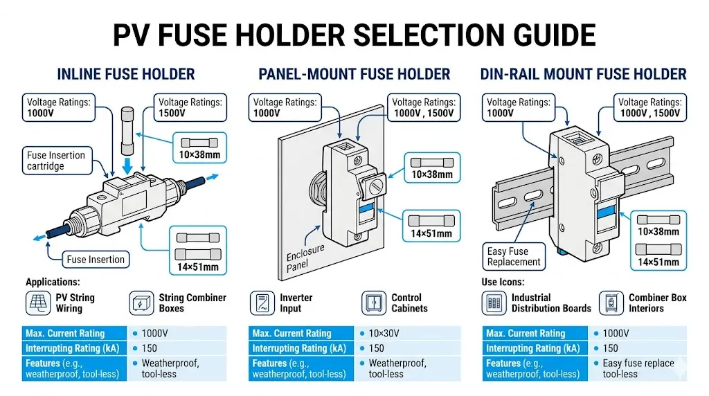
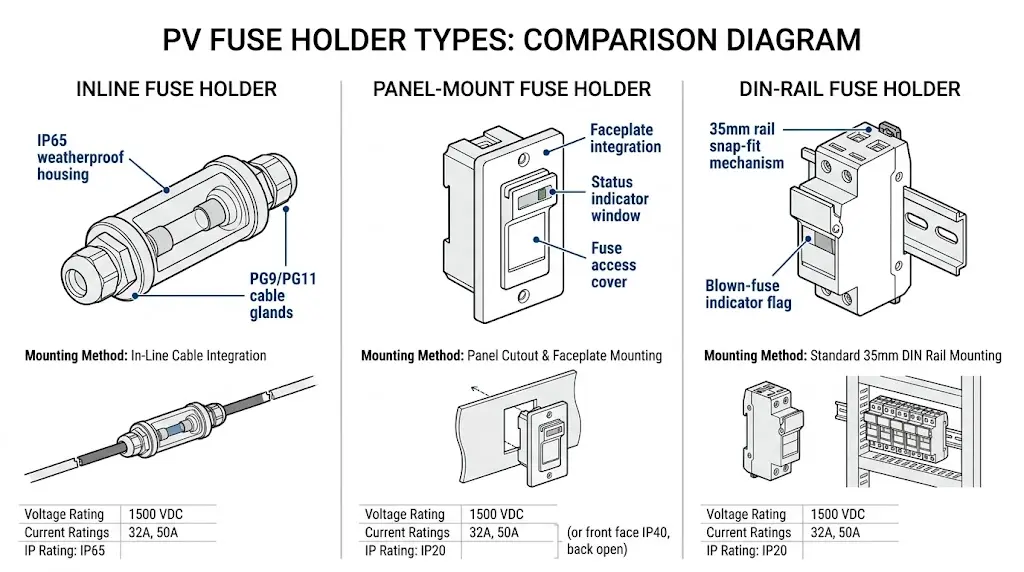
Die Auswahl des richtigen PV-Sicherungshaltertyps erfordert die Anpassung der physischen Konfiguration an die Installationsanforderungen. Bei dem Projekt in Jiangsu konnte durch den Wechsel von Inline-Sicherungshaltern zu DIN-Schienen-Sicherungshaltern die Wartungszeit um 65% reduziert und drei Fälle von unsachgemäßem Sicherungsaustausch, die zu String-Ausfällen geführt hatten, beseitigt werden.
Inline-Sicherungshalter werden direkt in der DC-Strangverdrahtung angeschlossen und typischerweise in kleineren Wohnanlagen bis zu 10 kW verwendet. Diese Halter nehmen zylindrische Sicherungen (in der Regel 10×38 mm oder 14×51 mm) auf und verfügen über die Schutzart IP65 oder höher für die Montage in Verteilerkästen im Freien. Das kompakte Design eignet sich für Anwendungen, bei denen PV-Kombinatorkästen sind unpraktisch, obwohl der Zugang zu den Sicherungen zum Auswechseln das Abklemmen des Kabels erfordert.
Konfigurationen für die Schalttafelmontage lassen sich in die Frontplatten von Verteilerkästen integrieren und bieten eine visuelle Anzeige des Sicherungsstatus sowie einen werkzeuglosen Austausch. Diese Halter nehmen in der Regel 10×38 mm gPV-Sicherungen mit einem Nennwert von bis zu 32 A und 1500 VDC auf. Gemäß IEC 60269-6 müssen die Halter für die Schalttafelmontage den Kontaktdruck über den Betriebstemperaturbereich von -40°C bis +85°C aufrechterhalten, um eine thermische Schädigung an den Anschlusspunkten zu verhindern.
Auf DIN-Schienen montierte Sicherungshalter dominieren aufgrund ihrer Modularität und Wartungsfreundlichkeit bei Versorgungseinrichtungen und gewerblichen Anlagen. Auf Standard-DIN-Schienen mit 35 mm Durchmesser können Halter für Sicherungen der Größen 10×38 mm und 14×51 mm montiert werden, mit Nennströmen bis zu 50 A bei 1500 VDC. Diese Halter sind häufig mit Anzeigen für durchgebrannte Sicherungen ausgestattet - entweder mechanische Fahnen oder LED-Schaltungen -, die eine schnelle Identifizierung bei Routineinspektionen ermöglichen.
Moderne PV-Sicherungshalter verfügen über eine berührungssichere (fingersichere) Konstruktion gemäß IEC 60529 IP20 Mindestanforderungen für stromführende Teile. Dies verhindert den versehentlichen Kontakt mit stromführenden Klemmen während des Sicherungswechsels. Dies ist wichtig, da die PV-Strings tagsüber unter Strom stehen, auch wenn der Wechselrichter isoliert ist.
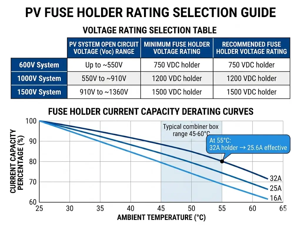
Die richtige Auswahl von Spannung und Stromstärke verhindert thermische Ausfälle, die bei der Jiangsu-Installation auftraten. Die Nennspannung des Sicherungshalters muss die maximale System-Leerlaufspannung unter den kältesten zu erwartenden Bedingungen übersteigen, während die Stromnennwerte die Reduzierung der Umgebungstemperatur berücksichtigen müssen.
| System-Klasse | Typischer Voc-Bereich | Minimalwert des Halters | Empfohlene Bewertung |
|---|---|---|---|
| 600V-Systeme | Bis zu 600 VDC | 700 VDC | 750 VDC |
| 1000V-Systeme | Bis zu 1000 VDC | 1100 VDC | 1200 VDC |
| 1500V-Systeme | Bis zu 1500 VDC | 1500 VDC | 1500 VDC |
Für Installationen in Höhenlagen über 2000 m gilt ein Spannungsderating. IEC 60947-1 legt Korrekturfaktoren für die Isolationskoordination fest, die in der Regel einen zusätzlichen Spannungsspielraum von 10-15% erfordern.
Der Dauerstrom des Halters muss dem Nennstrom der Sicherung entsprechen oder diesen übersteigen. Die Nennwerte auf dem Typenschild gehen jedoch von einer Umgebungstemperatur von 25 °C aus - Bedingungen, die im Sommer in Verteilerkästen selten anzutreffen sind.
Eine Fassung, die für 32 A bei 25°C Umgebungstemperatur ausgelegt ist, kann bei 55°C nur 25 A sicher handhaben. Fordern Sie von den Herstellern Temperatur-Derating-Kurven an und wenden Sie diese praktische Regel an: Wählen Sie für Systeme mit hohen Umgebungstemperaturen eine Fassung In ≥ 1,25 × Sicherung In. Gemäß IEC 60269-6 sollte der Temperaturanstieg an den Klemmenanschlüssen bei Nennstrom 65 K über der Umgebungstemperatur nicht überschreiten.
Der Sicherungshalter selbst hat kein Ausschaltvermögen - er ist auf die DC-Sicherung um den Fehlerstrom zu unterbrechen. Die Halterung muss jedoch den mechanischen und thermischen Belastungen während des Sicherungsbetriebs standhalten. Stellen Sie sicher, dass die Halterung getestet und für die Verwendung mit Sicherungen mit dem vorgesehenen Ausschaltvermögen ausgelegt ist, in der Regel 30-50 kA für PV-Nutzungsanwendungen.
[Experteneinblick: Temperaturderating in der Praxis]
- Die Innentemperaturen der Mähdrescherkästen erreichen während der sommerlichen Spitzenproduktion regelmäßig 55-65°C.
- Ein Derating-Faktor von 0,8 bei 55°C bedeutet, dass eine Halterung mit einem Nennstrom von 32 A sicher nur 25,6 A im Dauerbetrieb verarbeiten kann.
- Installation einer Temperaturüberwachung in repräsentativen Verteilerkästen im ersten Sommer des Betriebs
- Erwägen Sie belüftete Gehäusekonstruktionen für Installationen in heißen Klimazonen (>35°C durchschnittliche Umgebungstemperatur)
PV-Sicherungen haben standardisierte zylindrische Abmessungen, aber “Standard” garantiert keine universelle Kompatibilität. Maßtoleranzen, Kontaktdesigns und Anzeigemechanismen variieren von Hersteller zu Hersteller.
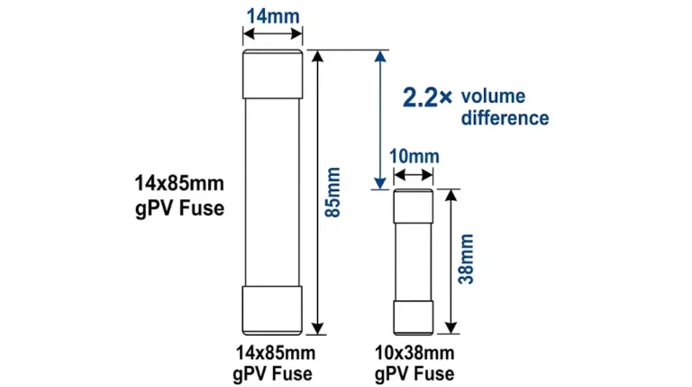
| Sicherung Größe | Durchmesser × Länge | Typischer Strombereich | Gemeinsame Bewerbung |
|---|---|---|---|
| 10×38 mm | 10,3 mm × 38,1 mm | 1 A - 32 A | Wohngebäude, gewerbliche Dachflächen |
| 14×51 mm | 14,3 mm × 51 mm | 25 A - 50 A | Hochstrom-Strings im Versorgungsbereich |
Die physische Passform allein gewährleistet noch keinen ordnungsgemäßen Betrieb. Überprüfen Sie diese Parameter, bevor Sie die Spezifikationen festlegen:
Bei der Angabe von GPV-Sicherungen und Halterungen vom selben Hersteller beziehen, wird die Kompatibilitätsunsicherheit beseitigt. Kombinationen aus verschiedenen Marken erfordern eine ausdrückliche Überprüfung durch den technischen Support des Herstellers oder physische Tests.
PV-Sicherungshalter arbeiten in anspruchsvollen Umgebungen: Temperaturschwankungen, UV-Einwirkung, Feuchtigkeit und Staub. Die Schutzart des Halters und die Materialauswahl entscheiden darüber, ob er 25 Jahre überlebt oder innerhalb von 5 Jahren ausfällt.
| Einbauort | Mindestinhaber IP | Empfohlenes Gehäuse IP |
|---|---|---|
| Elektrischer Innenraum | IP20 | IP20 |
| Belüftete Combiner-Box | IP20 | IP54 |
| Versiegeltes Außengehäuse | IP20 | IP65 |
| Direkte Exposition im Freien | IP65 | IP66 |
Die IP-Schutzart der Halterung gilt für den Einbau in ein Gehäuse. Das Gehäuse bietet primären Schutz vor Umwelteinflüssen; die Halterung bietet einen fingersicheren Schutz bei der Wartung.
Die Wahl des Materials wirkt sich direkt auf die Lebensdauer aus:
Bei einer schwimmenden 30-MW-PV-Anlage in der Provinz Anhui (2024) wiesen die verzinkten Standardbeschläge in den Sicherungshaltern des Verteilerkastens innerhalb von 8 Monaten sichtbare Korrosion auf. Durch den Austausch gegen Edelstahlbeschläge konnte das Problem gelöst werden - ein Spezifikationsdetail, das bei der ursprünglichen Planung oft übersehen wurde.
Erfahrungen aus der Praxis zeigen, dass es immer wieder zu Ausfällen von Sicherungshaltern kommt. Durch die Vermeidung dieser Fehler werden kostspielige Auswechslungen und Systemausfallzeiten vermieden.
1. Verwendung von AC-Haltern für DC-Anwendungen
AC-Sicherungshalter können identische Abmessungen, aber eine unzureichende Kriechstrecke für Gleichspannung aufweisen. Überprüfen Sie immer die explizite Gleichspannungsangabe - gehen Sie niemals davon aus, dass Wechselspannungsangaben übertragen werden.
2. Temperatur-Derating ignorieren
Eine Halterung, die für 32 A bei 25°C Umgebungstemperatur ausgelegt ist, kann bei 55°C nur 25 A verarbeiten. Fordern Sie Temperatur-Derating-Kurven für Ihre Installationsbedingungen an und wenden Sie diese an.
3. Vermischen von Sicherungs- und Haltermarken ohne Überprüfung
“Standard”-Maße haben Toleranzen. Physikalische Tests oder die Bestätigung von Querverweisen durch den Hersteller verhindern Passungsprobleme, die zu hochohmigen Verbindungen führen.
4. Übersehen von berührungssicheren Anforderungen
Die IEC 62548 (Anforderungen an die Konstruktion von Photovoltaikanlagen) schreibt berührungssichere Sicherungshalter an zugänglichen Stellen vor. Nicht konforme Installationen werden nicht geprüft und verursachen ein Haftungsrisiko.
5. Auswahl allein aufgrund des Preises
Die Kontaktqualität variiert dramatisch. Preisgünstige Halter mit schlechter Beschichtung entwickeln mit der Zeit einen hohen Kontaktwiderstand, der zu einer lokalen Erwärmung führt, die sowohl den Halter als auch die Sicherung beeinträchtigt - und letztlich teurer ist als Qualitätskomponenten.
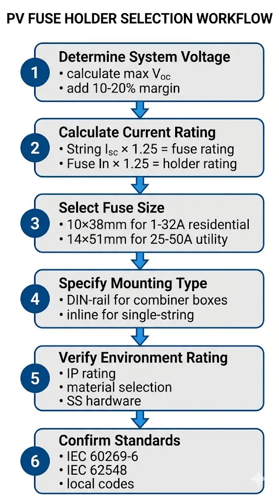
Dieser systematische Ansatz gewährleistet die richtige Auswahl der Sicherungshalter für jede PV-Anwendung:
Schritt 1: Bestimmung der Systemspannungsklasse
Ermitteln Sie die maximale Voc einschließlich Temperaturkorrektur für die kältesten zu erwartenden Bedingungen. Wählen Sie die Nennspannung des Halters mit einer Marge von 10-20% über diesem Wert.
Schritt 2: Berechnung des erforderlichen Nennstroms
String Isc × 1,25 = Mindestnennwert der Sicherung (gemäß NEC 690.9 oder gleichwertigem lokalen Standard). Dann gilt: Sicherung In × 1,25 = Mindestnennwert des Halters für Installationen mit hoher Luftfeuchtigkeit.
Schritt 3: Sicherungsgröße auswählen
Passen Sie die Stromstärke der Sicherungen an die verfügbaren Größen an. Für die meisten privaten und gewerblichen Anlagen werden 10×38 mm verwendet; für Hochstromstränge im Versorgungsbereich können 14×51 mm erforderlich sein.
Schritt 4: Bestimmen Sie die Befestigungsart
DIN-Schiene für Verteilerkästen und Verteilerfelder. Inline für einfache Anwendungen mit einem Strang oder wenn Verteilerkästen unpraktisch sind.
Schritt 5: Überprüfung der Umweltverträglichkeit
Bestätigen Sie die Eignung des Materials für die Installationsumgebung. Für Installationen in Küstennähe, schwimmende Installationen oder Installationen mit hoher Luftfeuchtigkeit sind Beschläge aus rostfreiem Stahl zu wählen.
Schritt 6: Bestätigung der Einhaltung von Normen
Überprüfen Sie die Einhaltung der IEC 60269-6 für die Sicherungseigenschaften, der IEC 62548 für die Anforderungen an PV-Generatoren und der geltenden örtlichen Elektrovorschriften.
Sinobreaker stellt PV-Sicherungshalter für 1000-V- und 1500-V-Solarsysteme her, die sich durch eine berührungssichere Konstruktion und Kompatibilität mit Standard-GPV-Sicherungsgrößen auszeichnen. Unsere Halter verwenden PA66-GF30-Gehäuse und versilberte Kupferkontakte, um die Leistung über den gesamten Betriebstemperaturbereich zu erhalten.
Die DC-Sicherung Produktlinie umfasst aufeinander abgestimmte Halter-Sicherungs-Kombinationen, die auf thermische Leistung und mechanische Zuverlässigkeit getestet wurden. Für komplette String-Schutzlösungen, erkunden Sie unser DC-Verteilerkästen mit werkseitig installierten Sicherungshaltern und DC-Schutzschalter für Haupttrennanwendungen.
Wenden Sie sich an das technische Team von Sinobreaker, wenn Sie Spezifikationen für Sicherungshalter, Kompatibilitätsprüfungen für bestimmte Sicherungsmarken, kundenspezifische Combiner-Box-Konfigurationen und projektspezifische Auswahlunterstützung benötigen.
Die meisten PV-Anlagen für Privathaushalte verwenden 10×38 mm große Sicherungshalter, die für 1000 VDC ausgelegt sind und Sicherungen von 10 A bis 25 A für typische Stringströme unter 10 A aufnehmen können.
Nein. AC-Halterungen verfügen nicht über eine ausreichende Kriechstrecke für Gleichspannung und können aufgrund von Kriechstrom oder anhaltenden Lichtbögen ausfallen - verwenden Sie immer Halterungen mit expliziten Nennwerten für Gleichspannung.
Jährliche Inspektionen im Rahmen der Routinewartung sind gängige Praxis. Nutzen Sie die Wärmebildtechnik bei Produktionsspitzen, um sich entwickelnde Kontaktwiderstandsprobleme zu erkennen, bevor sie zu Ausfällen führen.
Korrosion, thermische Wechselbeanspruchung, Lockerung durch Vibrationen und die Bildung von Oxidschichten auf den Kontaktflächen tragen alle dazu bei. Versilberte Kontakte widerstehen einer Verschlechterung besser als verzinnte Alternativen.
Nicht immer. Während 10×38 mm und 14×51 mm Standardgrößen sind, variieren Maßtoleranzen und Kontaktgeometrien. Überprüfen Sie die Kompatibilität durch Querverweise auf die Hersteller oder durch physische Tests.
Für den Sicherungshalter ist in der Regel die Schutzart IP20 für den Fingerschutz erforderlich; das Gehäuse des Kombinationskastens bietet die Schutzart IP65 oder IP66 für Außeninstallationen.
Die Indikatoren ermöglichen eine schnelle Identifizierung ausgefallener Sicherungen bei Routineinspektionen, ohne dass eine elektrische Prüfung erforderlich ist, was die Wartungszeit bei Systemen mit mehreren parallelen Strängen reduziert.