Adresse
304 Nord Kardinal
St. Dorchester Center, MA 02124
Arbeitszeiten
Montag bis Freitag: 7AM - 7PM
Am Wochenende: 10AM - 5PM
Adresse
304 Nord Kardinal
St. Dorchester Center, MA 02124
Arbeitszeiten
Montag bis Freitag: 7AM - 7PM
Am Wochenende: 10AM - 5PM

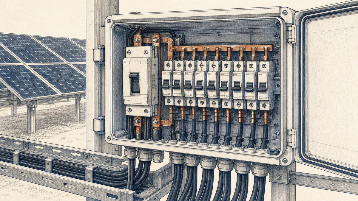
In photovoltaic systems, one fault should not turn into a full-site shutdown. A short circuit in a string circuit, combiner output, or DC feeder should be isolated as close to the fault as possible, while healthy circuits remain energized where the system design allows it. That is the purpose of **dc circuit breaker selective coordination**.
For Sinobreaker DC Circuit Breaker applications, selective coordination means arranging downstream and upstream protective devices so the breaker nearest the fault operates first. The goal is simple: protect conductors and equipment, reduce outage area, improve maintainability, and support safer troubleshooting in PV power systems.
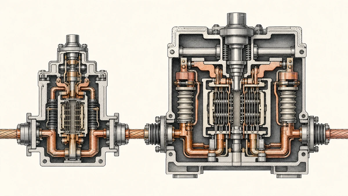
Selectivity is the coordination of protective devices so only the device immediately upstream of a fault opens. If a fault occurs on a downstream PV circuit, the downstream DC circuit breaker should clear it before an upstream feeder or main DC breaker trips.
This matters because upstream tripping can disconnect multiple strings, combiners, inverter inputs, or battery-coupled DC sections. Selective operation keeps the interruption local and preserves the rest of the supply.
PV circuits are not the same as conventional AC distribution circuits. Designers must account for:
A DC circuit breaker must be selected not only for voltage and current rating, but also for its ability to interrupt the prospective fault current at the installation point.
A coordinated design should be reviewed for more than one operating condition. Selective coordination should be checked for:
A breaker arrangement that coordinates under one current level may not coordinate under another. This is why device-specific trip curves and coordination data are essential.
The DC circuit breaker must be rated for the maximum system voltage. In PV applications, voltage can rise under cold conditions, so selection should consider the maximum open-circuit voltage of the array, not only nominal operating voltage.
Important checks include:
The available fault current at each point in the DC system must be estimated. In PV arrays, this may include current from parallel strings and other connected DC sources.
For coordination, the designer compares the prospective short-circuit current with:
Breaker coordination must protect the conductors connected to the circuit. Cable size, insulation rating, installation method, ambient temperature, grouping, and voltage drop can all influence the final breaker choice.
A breaker that coordinates electrically but does not protect the conductor correctly is not acceptable. The protective device must match both the circuit load and the conductor withstand limits.
Selective coordination depends on the relationship between devices. A downstream DC circuit breaker cannot be evaluated alone. Designers must compare it with the upstream breaker, fuse, switch-disconnector with protection, inverter input protection, or other protective device.
Coordination review should include:
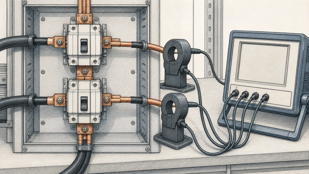
Total selectivity means the downstream breaker clears faults up to its rated breaking capacity without causing the upstream breaker to trip. In other words, for all fault currents the downstream breaker can safely interrupt, the upstream breaker remains closed.
This is the preferred result when continuity of service is critical. However, total selectivity depends on tested or published coordination data for the actual breaker models and settings used.
Partial selectivity means selective operation is achieved only up to a stated fault current. Above that current, both upstream and downstream devices may trip, or the upstream device may operate first.
Partial selectivity can still be useful when the maximum prospective current at the installation point is below the stated selectivity limit. The key is to verify the actual available current, not assume coordination.
PV systems can have different current contributions depending on array size, inverter topology, battery connection, and parallel source paths. A coordination study should confirm whether the selected Sinobreaker DC Circuit Breaker arrangement provides total selectivity or partial selectivity for the real system conditions.
If only partial selectivity is available, the design documentation should state the selectivity limit clearly.
Current-based coordination uses different current ratings or pickup thresholds between downstream and upstream breakers. The downstream breaker is selected or set to operate at a lower current level than the upstream device.
This method is simple, but it may not be enough in high short-circuit ranges where instantaneous elements operate very quickly.
Time-based coordination introduces a delay in the upstream breaker so the downstream breaker has time to clear the fault first. This is common where the upstream device has adjustable trip settings.
For DC PV circuits, time delay must be applied carefully because conductors and equipment must withstand the fault energy during the delay.
Energy-based coordination compares the let-through energy of the downstream device with the withstand capability and trip behavior of the upstream device. This is especially relevant for high fault currents where clearing times are very short.
Because energy behavior is device-specific, designers should use manufacturer coordination data rather than assumptions.
Logic-based coordination uses communication or interlocking between protective devices. In advanced DC systems, a downstream protective device can signal the upstream device to delay or block tripping while it clears the fault.
This method can support high selectivity, but it requires compatible devices, control power, verified wiring, and commissioning tests.
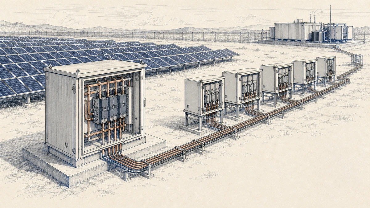
In a PV string circuit, a fault should be isolated without unnecessarily disconnecting other strings. Where string-level DC circuit breakers are used, they should be coordinated with combiner-level or inverter-input protection.
Designers should confirm that the string breaker can interrupt the available reverse current from parallel strings and any connected DC source.
Combiner output circuits often carry higher current and may feed inverter DC inputs or DC distribution equipment. A fault on the combiner output should ideally trip the combiner output breaker before the upstream main DC breaker.
Coordination at this level is important because nuisance tripping of a main DC breaker can remove a large portion of PV generation.
Inverter input circuits may involve multiple MPPT channels, recombiner panels, or long DC feeders. Breaker selection should account for the maximum DC voltage, expected operating current, available short-circuit current, and the coordination relationship with both upstream and downstream protection.
The breaker nearest the fault should open first whenever the confirmed selectivity range allows it.
PV systems with batteries, DC chargers, or hybrid inverters may have additional fault-current contribution. These systems require extra care because batteries can deliver higher and more sustained fault current than PV modules alone.
Each source configuration should be reviewed separately. A system may coordinate under PV-only conditions but require different breaker ratings or settings when battery contribution is included.
Before studying coordination, confirm that each DC circuit breaker is suitable for the basic circuit conditions:
Selective coordination requires comparing the time-current behavior of the downstream and upstream breakers. The downstream breaker should operate faster for the expected overload and short-circuit range, while the upstream breaker should remain closed within the coordinated region.
Where adjustable settings are available, set the upstream breaker above the downstream operating range, while still maintaining conductor and equipment protection.
Do not assume total selectivity. Confirm whether the breaker pair provides:
If the design depends on partial selectivity, verify that the maximum available fault current at that point is below the stated limit.
A complete PV coordination review should record:
This documentation helps installers, inspectors, maintenance teams, and future system designers understand how the protection scheme is intended to operate.
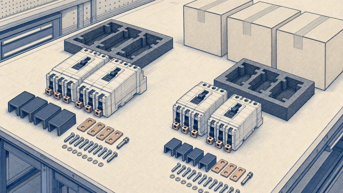
Rated current alone does not prove that a DC circuit breaker is suitable. Voltage rating, breaking capacity, DC interruption capability, trip characteristic, and coordination with adjacent devices all matter.
A downstream breaker may be correctly sized for its own circuit but still fail to coordinate with the upstream device. Selectivity is always a relationship between protective devices.
DC arcs are more difficult to interrupt than AC arcs because current does not naturally pass through zero. Use DC-rated breaker data for DC PV circuits.
PV systems are often expanded. Adding strings, combiners, batteries, or new inverter inputs can increase available fault current and change coordination results. Coordination should be reviewed when the system configuration changes.
It is the arrangement of downstream and upstream DC circuit breakers so the breaker closest to a fault opens first. The purpose is to isolate the faulty PV circuit while keeping unaffected circuits operating where the system design permits.
No. Total selectivity depends on the breaker models, ratings, settings, breaking capacities, and confirmed coordination data. Some designs provide only partial selectivity up to a stated current limit, which must be compared with the actual prospective short-circuit current.
Key inputs include maximum DC system voltage, design current, prospective short-circuit current, conductor size, installation conditions, upstream and downstream protective devices, and the required level of selectivity for overload, short-circuit, and earth-fault conditions.
DC circuit breaker selective coordination is essential for reliable PV protection. By selecting Sinobreaker DC Circuit Breakers with the correct voltage rating, breaking capacity, trip behavior, and coordination relationship, designers can help ensure that faults are cleared close to their source and that healthy downstream or parallel PV circuits remain available.
The best results come from checking each fault condition, each source configuration, and each upstream-downstream breaker pair with device-specific coordination data.