Adresse
304 Nord Kardinal
St. Dorchester Center, MA 02124
Arbeitszeiten
Montag bis Freitag: 7AM - 7PM
Am Wochenende: 10AM - 5PM
Adresse
304 Nord Kardinal
St. Dorchester Center, MA 02124
Arbeitszeiten
Montag bis Freitag: 7AM - 7PM
Am Wochenende: 10AM - 5PM

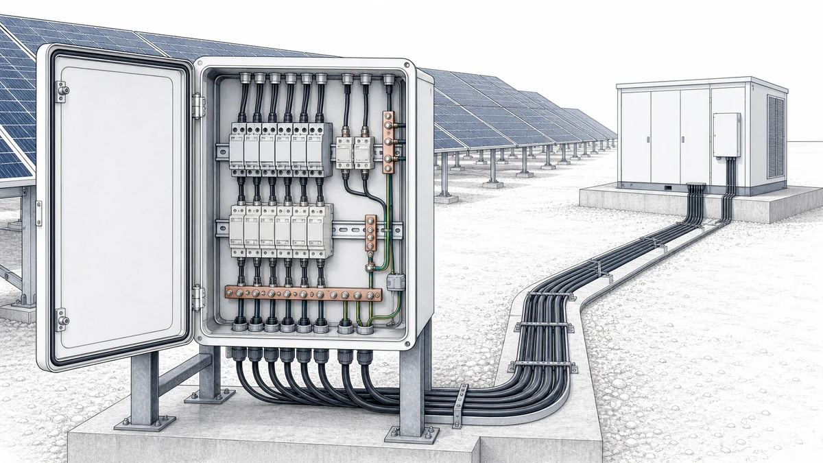
In photovoltaic systems, surge protection is not a matter of placing one device anywhere on the DC side and assuming the inverter is safe. Effective **pv spd coordination** means selecting and positioning DC surge protective devices so that string circuits, array combiner boxes, long DC cable runs, and inverter inputs work together as one protection concept.
For Sinobreaker DC SPD applications, the goal is simple: reduce dangerous transient overvoltages before they damage PV modules, combiner box components, monitoring devices, inverter DC inputs, or insulation systems. The practical design, however, depends on system voltage, topology, cable length, earthing arrangement, lightning exposure, and whether the PV installation has an external lightning protection system.
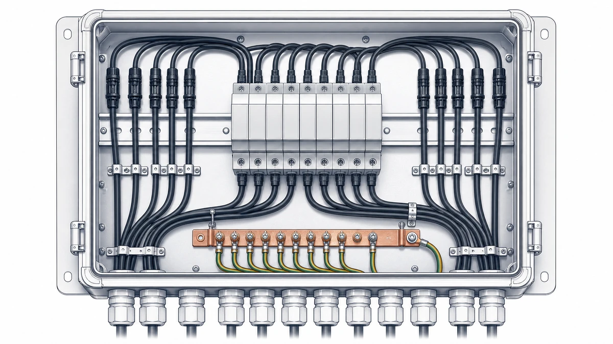
PV arrays are exposed electrical systems. Long module strings, metal mounting structures, outdoor cable routes, and inverter connections can all couple surge energy from lightning activity or switching events.
IEC 61643-32 addresses the selection, installation, and coordination of SPDs for PV systems, covering the path from the PV array through cabling and protective devices to the inverter and connection point. For the DC side, this means protection should be reviewed as a system, not as isolated products.
String level protection focuses on the DC circuits closest to the PV modules. This is especially relevant when strings are distributed over a large rooftop, carport, or ground-mounted field.
A DC SPD at or near the string aggregation point can help limit transient overvoltages before they travel deeper into the array wiring. In smaller systems, this may be located inside a string combiner or close to the module field. In larger systems, string level protection may be part of a layered design that also includes array-level and inverter-level SPDs.
Key design checks include:
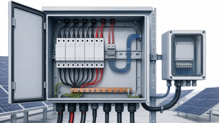
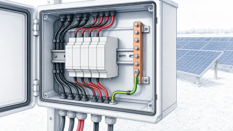
Array level protection is typically installed in a PV combiner box or DC junction box where multiple strings are collected. This is one of the most important locations for Sinobreaker DC SPD selection because the combiner box is often the interface between outdoor array wiring and longer DC feeders to the inverter.
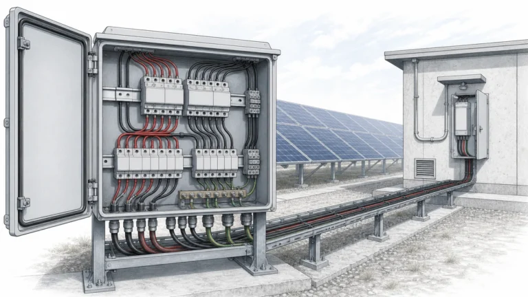
In central inverter solar parks, field generator junction boxes or DC combiner boxes may be located throughout the array field, while the inverter sits near a transformer station or power conversion area. In that topology, the array-level combiner box and the inverter input are separated by cable distance, so SPD coordination must consider both ends of the DC feeder.
The inverter is usually the most valuable and sensitive device on the DC side. Even when an SPD is installed at the array or combiner box, the inverter may still need its own DC SPD if the DC cable route is long or exposed.
A common design principle is to evaluate whether protection is needed at the other end of the cable when the distance between the PV array and inverter exceeds about 10 m. The exact requirement depends on cable routing, lightning risk, building structure, external lightning protection, and separation distance.
For Sinobreaker DC SPD projects, inverter input protection should be reviewed when:
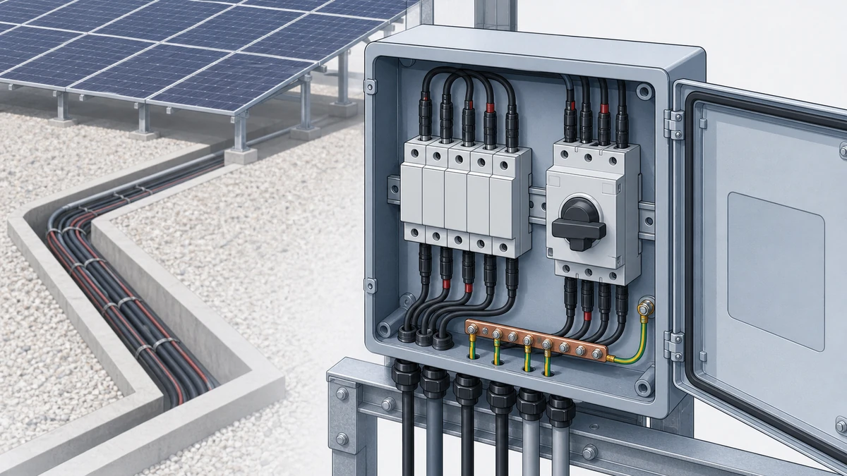
PV surge protection is location-sensitive. A DC SPD near the modules does not provide the same protection as one at the inverter input, and an inverter-side SPD does not fully protect exposed array cabling.
SPDs near the PV module field are used when the array is highly exposed or when the distance from the modules to the next protective device is significant. Rooftop systems with external lightning protection often require careful evaluation of separation distance between the PV array and lightning protection conductors.
If separation distance is not maintained, higher-energy SPD selection may be required because partial lightning current can enter the PV wiring system.
The PV combiner box is a natural coordination point because it may already contain string fuses, DC disconnects, monitoring modules, and outgoing feeder terminals. Installing a Sinobreaker DC SPD here helps protect both the combiner components and downstream inverter feeder.
A coordinated combiner box design should consider:
The inverter-side SPD is selected to protect the DC input stage and insulation system from residual surge voltage arriving through the feeder. This is particularly important in systems where the inverter is located far from the array or inside a technical room while the array is outdoors.
Inverter-level protection should not be treated as a replacement for array-level protection. Instead, it should be coordinated with upstream DC SPDs so that surge energy is limited progressively.
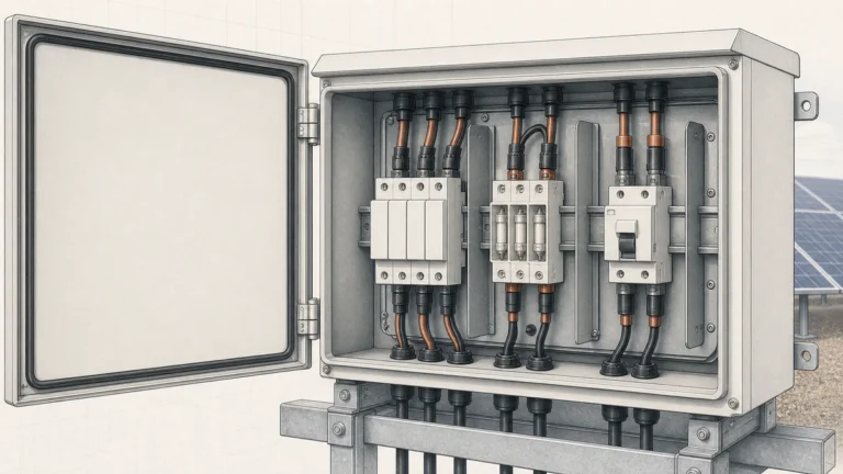
The correct DC SPD type depends on lightning exposure, external lightning protection, and the installation position.
A Type 1 DC SPD is used where the PV system may carry partial lightning current, such as installations with an external lightning protection system where safe separation distance cannot be maintained.
Type 1 SPDs are designed for high-energy impulse currents and are typically considered at array entry points, combiner boxes, or inverter inputs depending on the topology.
A Type 2 DC SPD is commonly used for induced surges and switching overvoltages. In many PV systems without direct lightning current risk, Type 2 protection at the combiner box and/or inverter input is the practical solution.
For Sinobreaker DC SPD selection, Type 2 devices are often suitable for standard rooftop and ground-mounted PV applications when the design assessment confirms there is no partial lightning current requirement.
A Type 1+2 DC SPD combines lightning current discharge capability and voltage-limiting performance in one device. It can simplify coordination where both high-energy exposure and equipment protection are required at the same installation point.
The decision between Type 1, Type 2, and Type 1+2 should be based on project conditions rather than a fixed rule.
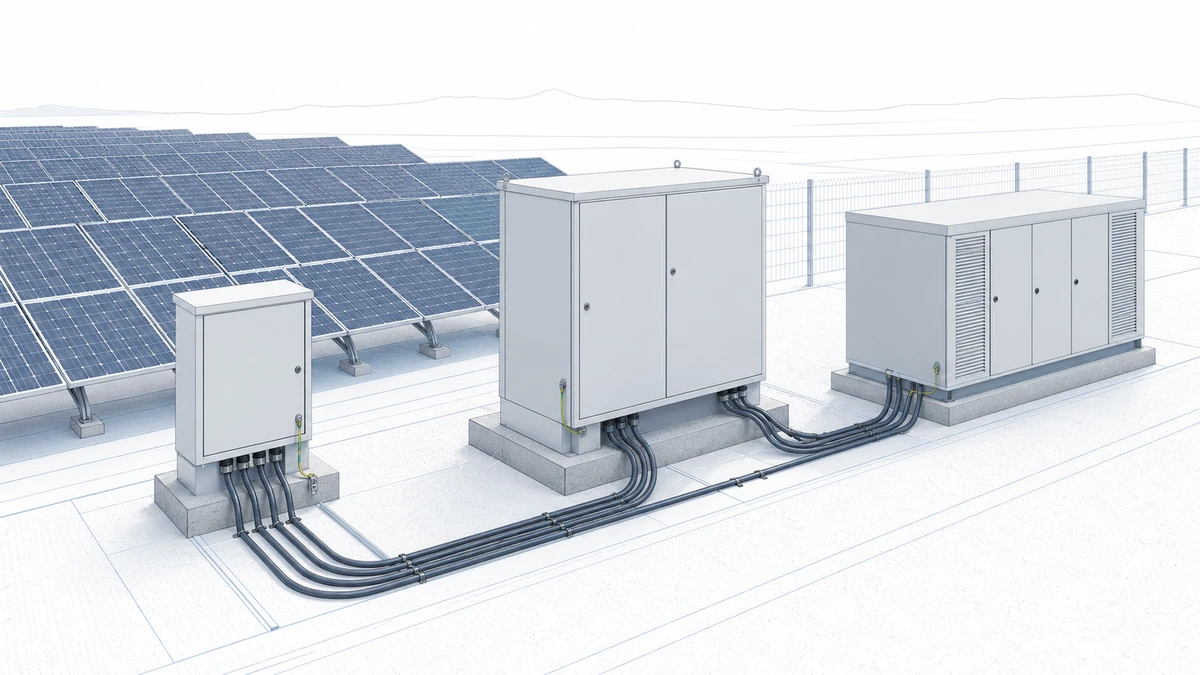
PV SPD coordination is not only about location. The electrical ratings must match the DC system.
The SPD maximum continuous operating voltage must be higher than the maximum PV array open-circuit voltage under cold conditions. This is critical because PV string voltage rises when temperature drops.
If the SPD voltage rating is too low, it may operate incorrectly or fail prematurely. If it is too high, the protection level may be less effective for the inverter and connected equipment.
The voltage protection level indicates the residual voltage that may appear downstream during a surge event. Lower protection levels generally improve equipment protection, but the SPD must still be suitable for the system voltage and energy exposure.
Coordination should ensure that the residual voltage at the inverter input remains within the withstand capability of the protected equipment.
PV arrays behave differently from conventional AC sources. The SPD and any internal or external disconnection system must be suitable for the maximum PV short-circuit current available at the installation point.
This is especially important in combiner boxes where multiple strings are paralleled and fault current capability is higher than at a single string.
DC SPD selection depends on whether the PV system is floating, functionally earthed, or configured with another earthing arrangement. The protection mode between positive, negative, and PE must match the system design.
Incorrect earthing assumptions can result in poor protection, nuisance operation, or unsafe fault behavior.
Cable length is one of the most practical triggers for additional SPD placement. When the cable between the PV array and inverter is long, surge voltage can build up along the route even if one end is protected.
If the panel-to-inverter or combiner-to-inverter cable exceeds approximately 10 m, designers should evaluate whether an additional DC SPD is needed at the opposite end. This does not mean every project has the same answer, but it does mean the cable route becomes part of the protection design.
Longer cables increase:
In a rooftop PV system, a combiner box may be installed near the module field, while the inverter is placed in an electrical room 20 m away. In this case, a Sinobreaker DC SPD in the combiner box helps protect the array-side equipment, but the inverter input may still require a second coordinated DC SPD.
In a compact rooftop system where the inverter is located directly beside the array connection point and cable length is short, a single correctly rated DC SPD may be sufficient if lightning risk and separation distance allow it.
External lightning protection changes the SPD design. If the PV array is installed on a building with air terminals, down conductors, or a lightning protection mesh, the PV wiring must be evaluated for separation distance.
If the required separation distance between the PV system and external lightning protection system is maintained, induced surge protection may be sufficient in many cases. Type 2 DC SPDs are commonly evaluated for these conditions.
If separation distance cannot be maintained, partial lightning current may enter the PV DC circuits. In this case, Type 1 or Type 1+2 DC SPD selection may be necessary at the relevant entry or transition points.
This is why rooftop guidance often shows different DC SPD locations near panels and inverters depending on the project. The correct solution is a coordination exercise, not a fixed one-SPD rule.
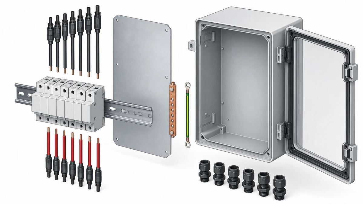
For a coordinated PV combiner box and inverter protection design, review the following before selecting a Sinobreaker DC SPD:
A small residential rooftop system and a central-inverter solar park do not have the same DC topology. The SPD locations must follow the actual route from strings to combiner boxes to inverter inputs.
If the inverter is far from the combiner box, a combiner-side SPD alone may not adequately protect the inverter. Long cable runs should trigger both-end evaluation.
PV DC circuits require SPDs specifically rated for DC operation and PV fault behavior. AC SPD ratings are not interchangeable with DC SPD ratings.
SPDs are protective devices that may need inspection or replacement after surge events. Visual status windows and remote signaling contacts help maintenance teams identify failed or end-of-life devices quickly.
PV SPD coordination is the process of selecting and placing DC surge protective devices so that PV strings, combiner boxes, cable routes, and inverter inputs are protected as one system. It considers SPD type, voltage rating, cable length, lightning exposure, earthing, and installation location.
You may need DC SPDs at both locations when the cable between the PV array or combiner box and inverter is long, commonly when it exceeds about 10 m, or when the route is exposed to lightning-induced surges. The final decision depends on project topology, external lightning protection, separation distance, and inverter requirements.
The correct Sinobreaker DC SPD depends on the PV system voltage, maximum short-circuit current, lightning risk, earthing arrangement, and whether Type 1, Type 2, or Type 1+2 protection is required. For standard induced surge protection, Type 2 is commonly evaluated; where partial lightning current is possible, Type 1 or Type 1+2 may be needed.