Adresse
304 Nord Kardinal
St. Dorchester Center, MA 02124
Arbeitszeiten
Montag bis Freitag: 7AM - 7PM
Am Wochenende: 10AM - 5PM
Adresse
304 Nord Kardinal
St. Dorchester Center, MA 02124
Arbeitszeiten
Montag bis Freitag: 7AM - 7PM
Am Wochenende: 10AM - 5PM


Solar system protection encompasses the integrated suite of devices and strategies preventing electrical damage, fire hazards, and shock risks in photovoltaic installations. Unlike traditional AC electrical systems where protection focuses primarily on fault current interruption, solar DC systems require multi-layered protection addressing overcurrent (excessive current flow), overvoltage (lightning and switching surges), arc faults (electrical arcing from damaged conductors), and ground faults (insulation breakdown allowing current leakage).
Statistics from the National Fire Protection Association reveal that 65% of solar system fires originate from electrical failures—42% from arc faults and 23% from ground faults—highlighting protection system criticality. Meanwhile, surge-related equipment damage costs the solar industry $180-250 million annually in inverter replacements and downtime. Yet field studies show only 55-60% of residential installations implement comprehensive protection beyond minimum code requirements, leaving systems vulnerable to preventable failures.
This educational guide explains solar system protection fundamentals for installers, facility managers, and system owners. You’ll learn the five core protection types required by NEC Article 690, how overcurrent devices prevent conductor overheating and fires, overvoltage protection strategies for lightning and surge events, coordination between protection layers ensuring selective operation, and equipment selection matching system voltage and current ratings. Whether managing a 5kW residential array or 5MW utility installation, understanding protection basics prevents the 85% of electrical failures caused by inadequate or improperly applied protective devices.
💡 Kritische Einsicht: Solar system protection differs fundamentally from AC electrical protection—DC circuits sustain arcs continuously without zero-crossing interruption, voltage accumulates across series-connected modules rather than transforming down, and “always-energized” operation prevents traditional lockout/tagout de-energization, requiring specialized protection approaches.
Solar photovoltaic systems face unique electrical hazards requiring protection strategies beyond conventional AC electrical installations. The National Electrical Code Article 690 defines five mandatory protection categories.
Overcurrent protection: Devices (fuses, circuit breakers) that interrupt excessive current from short circuits, ground faults, or reverse current conditions before conductors overheat causing insulation failure and fire. Required by NEC 690.9 when circuit current can exceed conductor ampacity.
Overvoltage protection: Surge protective devices (SPDs) that limit transient voltage spikes from lightning strikes, utility switching, or inverter operation, preventing damage to sensitive electronics. Required by NEC 690.35(B) for systems with metal-framed modules.
Arc fault protection: Detection systems monitoring for electrical arcing signatures indicating damaged conductors, loose connections, or insulation breakdown. Arc fault circuit interrupters (AFCI) required by NEC 690.11 for DC circuits >80V.
Ground fault protection: Monitoring that detects current leakage from DC conductors to ground, indicating insulation failure. Ground fault protection devices (GFPD) required by NEC 690.41 for grounded PV arrays to prevent shock hazards and fires.
Rapid shutdown: Systems reducing conductor voltage to ≤80V within 10 seconds of emergency activation, protecting firefighters and maintenance personnel from shock. Required by NEC 690.12 for installations after 2017.
Arc sustainability: AC current naturally crosses zero 120 times per second (60Hz), momentarily extinguishing arcs. DC current has no zero-crossing—once an arc initiates, it sustains indefinitely until current is externally interrupted.
Cumulative voltage: Series-connected modules add voltages—20 modules at 40V each produce 800V string voltage. Unlike AC systems with transformers stepping voltage down, DC solar maintains full string voltage from array to inverter.
Backfeed current: In parallel string configurations, healthy strings can feed current backward into faulted strings, exceeding individual string ratings. This unique failure mode requires string-level overcurrent protection absent in many AC systems.
Persistent ground faults: AC ground faults typically cause immediate breaker operation due to high fault current. DC ground faults may persist below breaker trip threshold but at currents sufficient to start fires through resistive heating over days or weeks.
690.8 Circuit Sizing and Current: Establishes that circuit conductors must handle maximum circuit current (125% of PV short-circuit current) with appropriate temperature and conduit fill derating.
690.9 Overcurrent Protection: Requires OCPD when circuits can supply currents exceeding conductor ampacity—typical in paralleled string configurations where backfeed occurs.
690.11 Arc-Fault Circuit Protection: Mandates AFCI for DC PV circuits >80V, detecting and interrupting arcs within 0.5-1.0 seconds preventing fire ignition.
690.35 Ungrounded Systems: Specifies ground fault detection for ungrounded systems, and overvoltage protection for systems with exposed conductive surfaces.
690.41 Ground-Fault Protection: Requires GFPD for grounded arrays, detecting insulation failures and disconnecting faulted equipment.
Overcurrent protection devices (OCPD) prevent conductor damage from excessive current by interrupting the circuit when current exceeds rated values. Solar systems use two primary OCPD types: fuses and circuit breakers.
Design purpose: Fuses designed specifically for photovoltaic DC applications, rated for high voltage (600V, 1000V, 1500V) and optimized for DC arc interruption.
gPV designation meaning:
– “g” = Full-range breaking capacity (protects from overload and short circuit)
– “PV” = Photovoltaic application (meets IEC and UL standards for solar)
Operating principle: Internal element (typically copper or silver strip) heats under current flow. At rated current, element temperature remains below melting point. Above rated current, element melts, creating air gap and arc. Arc energy vaporizes element material, increasing gap width until arc cannot sustain, interrupting current.
Key specifications:
Rated current (In): Continuous current fuse handles indefinitely. For solar strings, select 156% of string short-circuit current (Isc) per NEC 690.8(B).
Breaking capacity: Maximum fault current fuse can safely interrupt. PV fuses typically rated 10-30kA DC, sufficient for solar array available fault currents.
Time-current characteristic: I²t rating determining how quickly fuse operates at various overcurrents. Lower I²t provides faster protection but may nuisance-trip during cold temperature high-current conditions.
Example sizing: 10A Isc string requires:
– 10A × 1.56 = 15.6A minimum fuse rating
– Select next standard size: 15A or 20A gPV fuse
– Verify breaking capacity ≥ available fault current
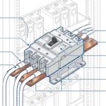
Design difference from AC: DC circuit breakers include arc chutes, magnetic blowouts, or electronic arc detection to extinguish DC arcs lacking natural zero-crossing.
Breaker types:
Thermal-magnetic: Bimetallic strip provides thermal overload protection (slow trip), electromagnetic coil provides instantaneous short-circuit protection (fast trip). Most common for solar applications 50-200A range.
Molded case circuit breaker (MCCB): Higher current capacity (200-1200A), manual operation, available with electronic trip units for precise current monitoring. Used for main array disconnects.
Miniature circuit breaker (MCB): Lower current ratings (1-63A), DIN rail mounting, modular design. Common in combiner boxes for string-level protection.
Critical rating verification: Breaker nameplate must explicitly state DC voltage rating. “AC/DC” marking is inadequate—verify specific DC voltage (e.g., “600V DC” or “1000V DC”). Never use AC-only breakers in DC circuits—arc interruption will fail, causing breaker destruction and fire.
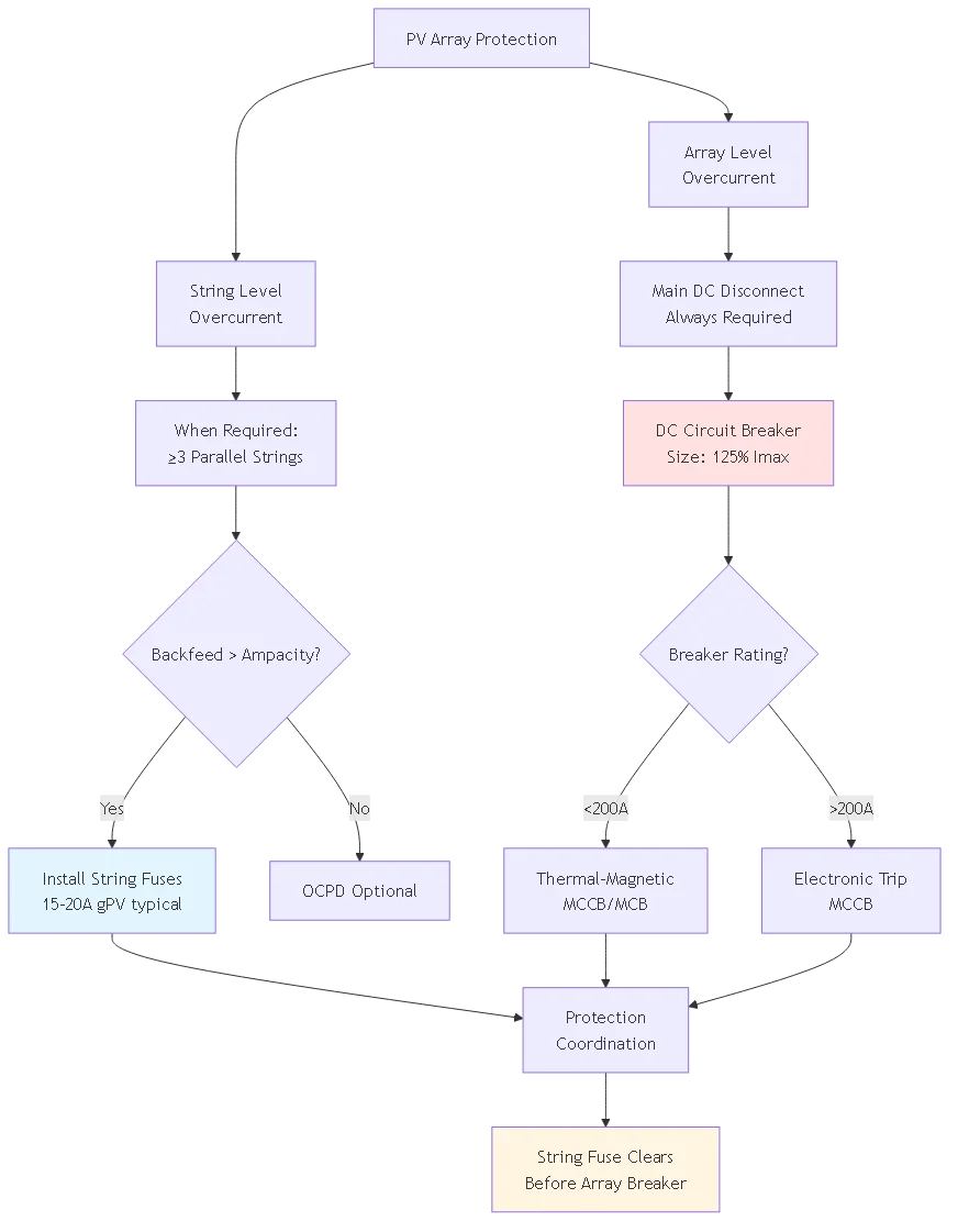
String-level OCPD (required when ≥3 strings parallel):
Each string requires individual fuse or breaker protecting against backfeed current from other parallel strings. Installed in combiner box or string-level disconnect.
Berechnung: Maximum backfeed current = (N-1) × Isc where N = number of parallel strings.
Beispiel: 6 strings, 10A Isc each
– Backfeed = 5 × 10A = 50A
– String conductor ampacity = 30A (10 AWG in conduit)
– 50A > 30A therefore string OCPD required
– Select 15A fuse per previous sizing example
Array-level OCPD:
Main DC circuit breaker between combiner output and inverter input. Sized at 125% of maximum circuit current (sum of all string currents × 1.25 temperature factor).
Beispiel: 6 strings × 10A × 1.25 = 75A
– Select 80A or 100A DC-rated breaker
– Verify interrupt rating exceeds available fault current
– Use as main DC disconnect per NEC 690.15
Overvoltage transients—brief voltage spikes lasting microseconds to milliseconds—originate from lightning strikes, utility switching operations, or inverter faults. Surge protective devices (SPDs) limit these transients to safe levels.
Direct lightning strikes: 20,000-200,000 amperes in <100 microseconds. creates voltage spike exceeding 100,000v on conductors if unprotected. frequency: 0.01-1.0 events per system year depending regional lightning density.Indirect lightning (nearby strikes): Electromagnetic pulse from strike 100-500 meters away induces 2,000-15,000V transients on conductors through magnetic coupling. Frequency: 1-10 events per year in high-lightning regions.
Utility switching: When utility opens/closes high-voltage switches or experiences faults, transients propagate to customer installations. Magnitude: 2,000-6,000V, duration 10-100 microseconds. Frequency: 2-20 events per year depending on grid quality.
Inverter switching: High-frequency switching (16-40 kHz) in inverter power stages creates repetitive low-energy transients. Magnitude: 500-2,000V, frequency: continuous during operation but well-controlled in quality inverters.
Metal oxide varistor (MOV): Semiconductor device with voltage-dependent resistance. Below clamping voltage (Uc), MOV presents megaohm impedance (effectively open circuit). Above Uc, resistance drops to ohms, diverting surge current to ground. After surge, MOV returns to high-impedance state.
Gas discharge tube (GDT): Gas-filled enclosure with electrodes. Below breakdown voltage, gas is insulator. Above breakdown, gas ionizes becoming conductive plasma, shorting transient to ground. Response time: 100-500ns (slower than MOV). Often paired with MOV for two-stage protection.
Silicon avalanche diode (SAD): Solid-state diode operating in avalanche breakdown region, clamping voltage with nanosecond response time. Used for low-voltage signal line protection (<100V). Higher cost than MOV limits solar DC application.
Type 1 SPD (Class I per IEC 61643-11):
Tested to 10/350 μs waveform simulating direct lightning current. Installed at service entrance or where partial lightning current exposure possible—DC homerun entry into building from rooftop array.
Ratings: 25-100 kA impulse current (Iimp), 2.5-4.0 kV voltage protection level (Up) for 1000V DC systems.
Type 2 SPD (Class II):
Tested to 8/20 μs waveform for induced surges and switching transients. Installed at distribution panels downstream of Type 1 protection.
Ratings: 20-40 kA nominal discharge current (In), 2.0-3.0 kV voltage protection level.
Type 3 SPD (Class III):
Equipment-level protection for sensitive circuits. Combination wave testing (1.2/50 μs voltage, 8/20 μs current).
Ratings: 5-10 kA discharge current, 1.0-1.5 kV voltage protection level.
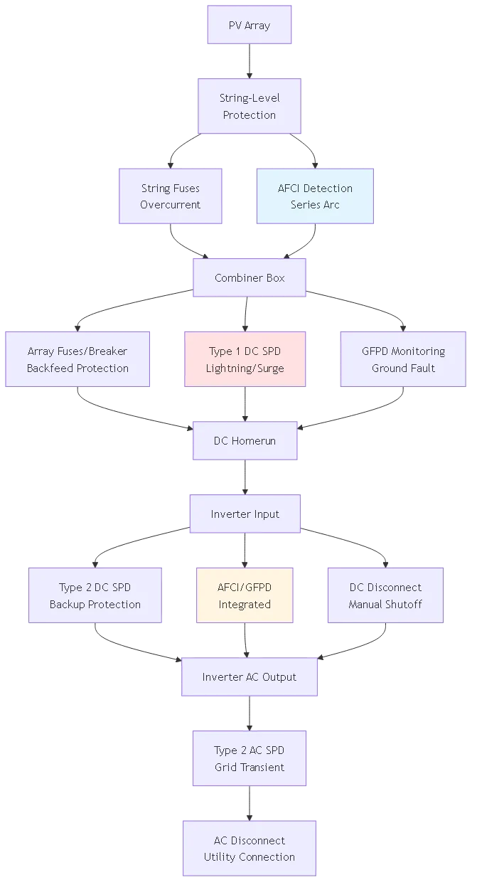
DC side protection:
Install Type 1 DC SPD at combiner box output (between strings and main DC conductors). This location protects array wiring from induced surges and provides first stage of inverter protection.
Install Type 2 DC SPD at inverter DC input terminals. This provides backup protection if combiner SPD fails and protects against transients entering on DC homerun conductors.
AC side protection:
Install Type 2 AC SPD at inverter AC output terminals or main AC disconnect. Protects inverter AC circuitry and utility interface from grid transients.
Install Type 3 AC SPD at monitoring equipment, communication circuits, and control panels if sensitive to transients.
Grounding requirement: All SPDs require connection to equipment grounding system. Use shortest practical conductor (≤12 inches) with minimum 6 AWG copper. Longer connections reduce SPD effectiveness—each foot of conductor adds inductive impedance at surge frequencies.
| SPD Type | Test Wellenform | Typical Rating | Solar Application |
|---|---|---|---|
| Type 1 (Class I) | 10/350 μs | 25-100 kA Iimp | Combiner box, DC homerun entry |
| Type 2 (Class II) | 8/20 μs | 20-40 kA In | Inverter DC/AC terminals |
| Type 3 (Class III) | 1.2/50-8/20 μs | 5-10 kA In | Monitoring, communications |
🎯 Profi-Tipp: SPD effectiveness depends on installation quality more than device rating. A $200 SPD with 6-inch ground lead outperforms a $500 SPD with 36-inch lead. Prioritize short, direct grounding connections using compression lugs and anti-oxidant compound.
Arc faults and ground faults represent the primary fire hazards in solar installations, accounting for 65% of electrical failures per NFPA statistics.
Detection principle: AFCI monitors current waveform for high-frequency signatures (100 kHz – 1 MHz) characteristic of electrical arcing. Normal DC current is smooth; arcing creates chaotic high-frequency noise from unstable plasma.
Processing algorithm: Microprocessor performs Fast Fourier Transform (FFT) on current signal, identifying frequency components. When arc signature persists >0.5 seconds (sustained arc vs momentary transient), AFCI opens circuit.
Arc types detected:
Series arc: Break in conductor or loose connection creating arc across gap. Example: Rodent-damaged wire, cracked module junction box solder joint.
Parallel arc: Arc between positive and negative conductors or conductor to ground. Example: Insulation wear-through allowing adjacent conductors to touch and arc.
Response time: NEC 690.11 requires interruption within 1 second of arc detection. Typical devices operate 0.3-0.8 seconds—fast enough to prevent ignition of most combustibles.
Integration approaches:
Inverter-integrated AFCI: Most modern residential inverters (>2017) include built-in AFCI monitoring DC input circuits. Advantage: No additional equipment cost. Limitation: Only protects circuits between combiner and inverter, not string wiring.
Combiner-level AFCI: Standalone devices in combiner boxes monitoring individual strings. Advantage: Protects entire DC circuit including string wiring. Disadvantage: Additional cost ($200-400 per combiner), more failure points.
Module-level AFCI: Power optimizers with integrated arc detection. Advantage: Detects arcs at module level. Disadvantage: Higher system cost ($0.20-0.30/W premium).
Detection principle: GFPD monitors current balance between positive and negative DC conductors using current transformer (CT) or hall-effect sensor. Imbalance indicates current leaking to ground through insulation failure.
Sensitivity: Typical setting 1 amp for systems <50kW. This detects insulation resistance <600Ω on 600V system (R = V/I = 600V/1A). Lower threshold increases nuisance trip risk; higher threshold misses incipient faults.Response: Upon detecting imbalance >1A for >0.3 seconds, GFPD signals inverter to shut down and opens DC disconnect. Must provide visual indication (LED, display) of fault condition per NEC 690.41(B).
Testing requirement: Push-button self-test simulates ground fault, verifying detection and interrupt functions. NEC 690.41 requires test capability but doesn’t mandate testing frequency—annual testing recommended.
AFCI nuisance trips: Electromagnetic interference (EMI) from improperly shielded equipment mimics arc signature. Prevention: Use shielded DC conductors in metal conduit, separate power and communication wiring, verify all equipment UL-listed for PV application.
GFPD false positives: Moisture infiltration in junction boxes creates temporary low-resistance path triggering fault detection. Prevention: Use junction boxes rated IP65 minimum, apply sealant at cable entries, inspect annually in high-humidity climates.
Missed arc detection: Module-to-module connector deterioration creates intermittent arcing below AFCI detection threshold. Prevention: Use only listed connectors (genuine MC4 or listed equivalents), pull-test all connections (50+ pound force), inspect quarterly in harsh environments.
Coordination ensures that when faults occur, only the protection device nearest the fault operates, leaving upstream protection intact to maintain system security.
Objective: Fuse or breaker closest to fault clears fault before upstream devices operate. This limits outage to smallest possible system portion.
Methode: Select devices with time-current curves providing adequate separation. Downstream device must clear fault in shorter time than upstream device requires to trip at same fault current.
Example coordination:
String fuse: 15A gPV, opens in 0.01 seconds at 100A fault current
Array breaker: 80A DC-rated, trips in 0.1 seconds at 100A
Separation: 0.09 seconds between operations = adequate coordination
If string fuse were 20A instead: Opens in 0.05 seconds—still faster than breaker. But if string fuse were 30A: Opens in 0.15 seconds—breaker trips first, de-energizing entire array instead of just faulted string.
Voltage clamping levels: Downstream SPD must have lower voltage protection level (Up) than upstream SPD. This ensures sensitive equipment sees lowest possible surge voltage.
Beispiel:
– Combiner Type 1 SPD: Up = 3.5 kV
– Inverter Type 2 SPD: Up = 2.5 kV
– Monitoring Type 3 SPD: Up = 1.5 kV
Surge entering system sees 3.5 kV at combiner, limited to 2.5 kV at inverter, further limited to 1.5 kV at monitoring equipment.
Let-through energy: Upstream SPD must absorb sufficient energy that downstream SPD isn’t overloaded. Type 1 (50 kA capacity) handles direct lightning effects, allowing Type 2 (20 kA capacity) to handle residual without failure.
Overcurrent device testing:
– Visual inspection for corrosion, damage, loose connections
– Resistance measurement across closed contacts (<0.1Ω indicates good contact)
- Fuse replacement on annual schedule or after any fault operationSPD testing:
– Check indicator lights (green = functional, red = failed, per manufacturer)
– Measure let-through voltage using surge generator (professional service)
– Replace SPDs after major lightning event even if indicator shows green
AFCI/GFPD testing:
– Press test button quarterly verifying trip operation
– Monitor trip logs for patterns indicating installation issues
– Firmware updates per manufacturer recommendations

Problem: AC breakers or SPDs used in DC solar systems. AC devices rely on current zero-crossing for arc extinction—absent in DC circuits, causing protection failure and fire risk.
Common scenarios:
– Standard residential AC breakers in DC combiner boxes
– MOV-only AC surge arresters on DC circuits (no DC follow-current interruption)
– Lighting panel breakers repurposed for DC disconnect
Berichtigung: Verify every component explicitly rated for DC at system voltage. Look for “DC” marking on nameplate plus specific voltage (e.g., “1000V DC”). AC/DC dual-rating acceptable only if DC voltage specifically listed. Replace any AC-only components immediately—this is life-safety issue.
Problem: Long, coiled grounding leads (>24 inches) connecting SPD to ground. Inductive impedance of long conductors reduces SPD effectiveness, allowing dangerous voltage to reach protected equipment.
Common scenarios:
– SPD mounted on panel door with 3-foot ground lead to cabinet busbar
– Coiled excess wire “stored” behind SPD
– 14 AWG or smaller grounding conductor (inadequate for surge current)
Berichtigung: Use shortest practical ground path—6-12 inches maximum. Route straight with no sharp bends or coils. Use minimum 6 AWG copper conductor with compression lugs. Apply anti-oxidant compound at connections. Consider relocating SPD if shorter ground path not achievable.
Problem: Relying on single protection device (e.g., combiner SPD only, no inverter SPD). Single-point failures leave system unprotected.
Common scenarios:
– Type 1 SPD at combiner but no Type 2 at inverter (surge enters on AC side unprotected)
– AFCI in inverter but no string-level detection (can’t isolate faulted string)
– Overcurrent protection but no surge protection (covers one failure mode, ignores others)
Berichtigung: Implement layered protection—overcurrent + overvoltage + arc fault + ground fault. Each layer addresses different failure mode. Cost increment ($500-1500 residential, $2000-5000 commercial) negligible compared to unprotected equipment replacement ($5,000-50,000).
Problem: Protection devices selected without verifying coordination. Results in nuisance trips where main breaker opens instead of string fuse, de-energizing entire system for single-string fault.
Common scenarios:
– Array breaker smaller than required, trips before string fuses clear
– String fuses oversized, don’t provide selective protection
– No time-current curve analysis performed
Berichtigung: Obtain time-current curves from manufacturers. Plot on logarithmic graph verifying minimum 0.05-second separation between downstream and upstream devices at expected fault currents. For systems >100kW, engage protection engineer for coordination study.
Problem: AFCI sensitivity set too high (less sensitive), missing real arc faults. Or set too low (more sensitive), causing nuisance trips from inverter switching noise.
Common scenarios:
– Using default AFCI settings without site-specific tuning
– Disabling AFCI after nuisance trips instead of investigating root cause
– Installing AFCI downstream of power optimizers (which mask arc signatures)
Berichtigung: Follow manufacturer commissioning procedure including sensitivity adjustment for site EMI environment. Investigate any AFCI trip—indicates real problem requiring correction (damaged conductor, loose connection). Never disable AFCI to “solve” nuisance tripping—fixes symptom while leaving fire hazard unaddressed.
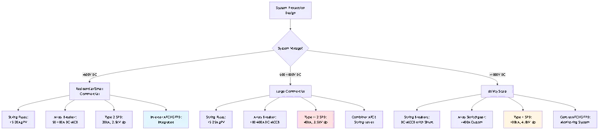
Solar systems require five core protection types per NEC Article 690: (1) Overcurrent protection using fuses or DC-rated breakers to prevent conductor overheating from excessive current, (2) Overvoltage protection with surge protective devices limiting lightning and switching transients, (3) Arc fault protection detecting and interrupting electrical arcing from damaged conductors, (4) Ground fault protection monitoring insulation resistance and detecting current leakage, (5) Rapid shutdown reducing conductor voltage during emergencies. Each protection type addresses different failure mode—overcurrent handles short circuits and backfeed, overvoltage protects against surges, arc fault prevents fires from damaged wiring, ground fault detects insulation breakdown, rapid shutdown ensures personnel safety. All five layers work together providing comprehensive protection. Missing any layer leaves system vulnerable to specific failure mode—example: excellent overcurrent protection but no surge protection means lightning events still destroy inverters. Cost for complete residential system protection: $1,500-2,500 including all five layers, representing 8-12% of total system cost but preventing 85% of electrical failures.
Overcurrent device sizing depends on circuit location and fault current exposure. For string-level fuses in parallel configurations, calculate maximum backfeed current: (Number of parallel strings – 1) × String short-circuit current (Isc). Then size fuse at 156% of string Isc per NEC 690.8(B)(1). Example: 10A Isc string with 6 parallel strings has backfeed = 5 × 10A = 50A. String conductor ampacity = 30A (10 AWG in conduit). Backfeed exceeds ampacity therefore string fuses required. Fuse size: 10A × 1.56 = 15.6A, select 15A or 20A standard gPV fuse. For array-level breaker between combiner and inverter, size at 125% of maximum circuit current: (Total parallel strings × Isc) × 1.25. Example: 6 strings × 10A × 1.25 = 75A, select 80A or 100A DC-rated breaker. Critical: Verify breaker DC voltage rating ≥ maximum system voltage and interrupt rating ≥ available fault current. Never round down on overcurrent device sizing—undersized devices cause nuisance trips and potential conductor damage.
SPD types differ in test requirements and installation location per IEC 61643-11 classification. Type 1 tested to 10/350 μs waveform simulating direct lightning current (25-100 kA impulse), installed at service entrance or locations with partial lightning exposure like DC homerun entry from rooftop array into building. Type 2 tested to 8/20 μs waveform for induced surges (20-40 kA discharge current), installed at distribution panels and inverter terminals downstream of Type 1 protection. Type 3 uses combination wave test (1.2/50 μs voltage, 8/20 μs current) for equipment-level protection (5-10 kA), installed at sensitive monitoring and communication circuits. Solar systems typically require Type 1 DC SPD at combiner box, Type 2 DC SPD at inverter DC input, Type 2 AC SPD at inverter AC output, and Type 3 for monitoring circuits. Energy coordination requires downstream SPD voltage protection level lower than upstream—example: Type 1 at 3.5kV, Type 2 at 2.5kV, Type 3 at 1.5kV. This staged approach progressively limits surge voltage as it propagates toward sensitive equipment. Cost: Type 1 $200-500, Type 2 $100-300, Type 3 $50-150 per device.
Arc fault circuit interrupters (AFCI) continuously monitor DC current waveforms using microprocessor-based signal analysis. Electrical arcs create high-frequency noise (100 kHz – 1 MHz) from unstable plasma—AFCI performs Fast Fourier Transform identifying these characteristic frequency signatures. Normal DC current is smooth with minimal high-frequency content. When arc signature persists >0.5 seconds (sustained arc vs momentary transient), AFCI determines dangerous arcing present and opens circuit within 1 second per NEC 690.11. Modern AFCIs distinguish between harmful arcs (damaged conductors, loose connections) and benign high-frequency noise (inverter switching, motor starts) using pattern recognition algorithms trained on thousands of arc fault waveforms. Most residential inverters manufactured after 2017 include integrated AFCI monitoring DC circuits. Commercial systems may use standalone AFCI devices in combiner boxes providing string-level arc detection. Module-level power electronics (optimizers, microinverters) often integrate AFCI at module level. Testing: Monthly or quarterly button press simulates arc signature verifying detection and interrupt functions operate correctly. Never disable AFCI—every trip indicates real problem requiring investigation and correction.
Ground faults occur when insulation breakdown allows current to leak from DC conductors to grounded module frames or mounting structure. Primary causes: UV degradation of conductor insulation (40%), rodent damage to wiring under arrays (25%), moisture infiltration in junction boxes (20%), and installation damage from sharp edges or over-tightened clamps (15%). Detection uses current transformer or hall-effect sensor monitoring current balance between positive and negative DC conductors. In healthy system with intact insulation, outgoing current must equal returning current. Any imbalance indicates leakage to ground. Ground fault protection devices (GFPD) trigger when imbalance exceeds threshold—typically 1 amp for systems <50kW, representing insulation resistance <600Ω on 600V system. Upon detection, GFPD signals inverter shutdown and opens DC disconnect within 10 seconds per NEC 690.41. Visual indication (LED, display) shows fault condition. Testing: Push-button self-test simulates ground fault verifying detection and interrupt functions. Recommended frequency: monthly during first year, quarterly thereafter. After any GFPD trip, measure insulation resistance using megohmmeter before resetting—readings <500kΩ indicate serious insulation failure requiring repair. Annual preventive testing using megohmmeter identifies degrading insulation before it progresses to fault condition.
Yes—both protection types are mandatory and address completely different failure modes. Overcurrent protection (fuses, breakers) prevents conductor damage and fire from excessive continuous or short-circuit current caused by equipment faults, backfeed, or ground faults. Response time: milliseconds to seconds depending on current magnitude. Protects against: internal system faults, short circuits, ground faults. Surge protection (SPDs) prevents equipment damage from brief voltage transients (microseconds to milliseconds duration) caused by lightning strikes, utility switching, or inverter faults. Response time: nanoseconds. Protects against: external surge events, lightning, grid disturbances. Neither can substitute for the other—overcurrent devices don’t respond to brief transients (below their trip threshold), while SPDs don’t interrupt sustained overcurrent. Real-world example: lightning induces 10,000V surge lasting 50 microseconds. Overcurrent device doesn’t trip (too brief), but SPD clamps voltage to 2,500V preventing inverter damage. Separately, short circuit creates 500A continuous current. SPD can’t interrupt this current (not designed for sustained conduction), but fuse opens in 0.01 seconds preventing conductor fire. Complete protection requires both device types working together—cost $800-1,500 residential, $2,000-5,000 commercial, representing minor fraction of total system investment.
Protection device maintenance frequency depends on type and exposure. Overcurrent devices (fuses, breakers): Visual inspection annually checking for corrosion, damage, or loose connections. Measure contact resistance (<0.1Ω = good). Replace fuses after any operation or on 3-5 year schedule even if no faults. Test breakers by cycling (open/close) under no-load quarterly. Surge protection devices: Check indicator monthly (green = functional, red = failed). Replace after major lightning event even if indicator shows good—internal damage may not immediately show. Typical SPD life: 5-10 years in low-lightning regions, 3-5 years high-lightning areas. Arc fault circuit interrupters: Press test button monthly during first year, quarterly thereafter. Review trip logs if inverter-integrated—frequent nuisance trips indicate installation issues requiring correction. Firmware updates per manufacturer schedule. Ground fault protection: Monthly button test during first year, quarterly thereafter. Annual insulation resistance measurement using megohmmeter verifying system insulation >2MΩ. Any reading <500kΩ requires immediate investigation. Document all testing with dates, results, and corrective actions—insurance claims often require maintenance records proving proper system care. Budget $200-500 annually for residential protection system testing and maintenance, $1,000-3,000 commercial.
Solar system protection encompasses five integrated protection layers—overcurrent, overvoltage, arc fault, ground fault, and rapid shutdown—each addressing specific failure modes that together account for 95% of PV system electrical hazards. Unlike AC electrical systems where single-layer protection often suffices, DC solar installations require multi-layered approach due to sustained DC arcs, cumulative series voltages, and persistent ground fault characteristics unique to photovoltaic applications.
Wichtigste Erkenntnisse:
1. All five protection types are mandatory—NEC Article 690 requires overcurrent (690.9), arc fault (690.11), ground fault (690.41), and rapid shutdown (690.12) protection as minimum, with overvoltage protection (690.35) for most installations. Omitting any layer leaves system vulnerable to specific failure mode.
2. DC-rated components are non-negotiable—AC breakers, fuses, or surge arresters fail catastrophically in DC circuits due to sustained arc characteristics. Every component must explicitly state DC voltage rating on nameplate.
3. Protection coordination prevents collateral damage—properly coordinated devices ensure only the protection nearest the fault operates, limiting outages to smallest system portion. String fuse should clear before array breaker at same fault current.
4. Short SPD ground leads are critical—surge protection effectiveness inversely proportional to ground conductor length. Each foot of conductor reduces SPD effectiveness 15-20%. Use 6-12 inch maximum ground path with 6 AWG minimum conductor.
5. Layered protection costs 8-12% of system investment—comprehensive protection ($1,500-2,500 residential, $5,000-15,000 commercial) represents minor fraction of total cost but prevents 85% of electrical failures causing average unprotected damage of $10,000-50,000 per event.
Investment in complete protection system—properly sized overcurrent devices, coordinated surge protection, functioning arc fault and ground fault detection—costs far less than single unprotected failure causing equipment destruction, fire damage, and potential injury liability. Protection isn’t optional enhancement—it’s fundamental requirement for safe, reliable solar operation.
Verwandte Ressourcen:
- DC Circuit Breaker Selection for Solar Protection
- DC SPD Types and Surge Protection Coordination
- Solar Panel Lightning Protection Methods
Ready to implement comprehensive protection for your solar installation? Contact our protection engineering team for system-specific overcurrent device sizing, surge protection coordination analysis, arc fault and ground fault monitoring specification, and complete protection system design. We provide turnkey solutions from initial protection requirements analysis through commissioning testing and documentation for building authority approval.
Zuletzt aktualisiert: February 2026
Autor: SYNODE Technisches Team
Rezensiert von: Electrical Protection Engineering Department
Schwerpunkt Stichwort: solar system protection
URL Slug: what-is-solar-system-protection-overcurrent-overvoltage
Meta-Titel: What is Solar System Protection? Overcurrent & Overvoltage Basics
Meta-Beschreibung: Learn what is solar system protection: overcurrent devices (fuses, breakers), overvoltage protection (SPD), arc fault detection, ground fault monitoring, and NEC 690 requirements.
Inhaltliche Ebene: Tier 3 (Supporting Content)
Umstellungstrichter: Top of Funnel (Bekanntheit)
Ziel-Wortzahl: 2800-4000 Wörter
Ziel Meerjungfrauen-Diagramme: 3
Bitte konfigurieren Sie diese in den Rank-Math-Einstellungen und löschen Sie dann dieses Feld vor der Veröffentlichung.
Solar systems require five core protection types per NEC Article 690: Overcurrent protection using fuses or DC-rated breakers, overvoltage protection with surge protective devices, arc fault protection detecting electrical arcing, ground fault protection monitoring insulation resistance, and rapid shutdown reducing conductor voltage during emergencies. Each addresses different failure mode. All five layers work together providing comprehensive protection. Missing any layer leaves system vulnerable. Complete residential system protection costs $1,500-2,500 representing 8-12% of total cost but preventing 85% of electrical failures.
String-level fuse sizing: Calculate maximum backfeed current (Number of parallel strings – 1) × String Isc, then size fuse at 156% of string Isc per NEC 690.8(B)(1). Example: 10A Isc string with 6 parallel strings needs backfeed calculation 5 × 10A = 50A. If backfeed exceeds conductor ampacity, fuses required. Size: 10A × 1.56 = 15.6A, select 15A or 20A gPV fuse. Array-level breaker sizing: 125% of maximum circuit current (Total strings × Isc) × 1.25. Verify DC voltage rating and interrupt rating adequate.
Type 1 tested to 10/350 μs waveform simulating direct lightning (25-100 kA), installed at service entrance or DC homerun entry from rooftop. Type 2 tested to 8/20 μs for induced surges (20-40 kA), installed at inverter terminals downstream of Type 1. Type 3 uses combination wave for equipment-level protection (5-10 kA), installed at monitoring circuits. Solar systems need Type 1 DC SPD at combiner, Type 2 at inverter DC/AC terminals, Type 3 for monitoring. Coordination requires downstream SPD voltage protection level lower than upstream. Cost: Type 1 $200-500, Type 2 $100-300, Type 3 $50-150.
AFCIs continuously monitor DC current waveforms using microprocessor-based analysis. Electrical arcs create high-frequency noise (100 kHz – 1 MHz) from unstable plasma. AFCI performs Fast Fourier Transform identifying characteristic signatures. When arc signature persists >0.5 seconds, AFCI opens circuit within 1 second per NEC 690.11. Modern AFCIs distinguish harmful arcs from benign high-frequency noise using pattern recognition. Most residential inverters after 2017 include integrated AFCI. Testing: Monthly button press verifies detection functions. Never disable AFCI—every trip indicates real problem requiring correction.
Ground faults occur when insulation breakdown allows current leakage from DC conductors to ground. Causes: UV degradation (40%), rodent damage (25%), moisture infiltration (20%), installation damage (15%). Detection uses current transformer monitoring balance between positive and negative conductors. GFPD triggers when imbalance exceeds 1 amp (insulation resistance <600Ω on 600V system). Upon detection, inverter shuts down within 10 seconds per NEC 690.41. Testing: Monthly button test recommended. After trips, measure insulation resistance with megohmmeter—readings <500kΩ require repair before reset.
Yes—both are mandatory and address different failure modes. Overcurrent protection prevents conductor damage from excessive continuous current (milliseconds to seconds response). Surge protection prevents equipment damage from brief voltage transients (nanoseconds response). Neither substitutes for the other. Example: Lightning surge of 10,000V lasting 50 microseconds—overcurrent device doesn’t trip (too brief), SPD clamps to 2,500V preventing damage. Separately, 500A short circuit—SPD can’t interrupt, fuse opens in 0.01 seconds preventing fire. Complete protection requires both, costing $800-1,500 residential, $2,000-5,000 commercial.
Overcurrent devices: Annual visual inspection, measure contact resistance, replace fuses after operation or 3-5 year schedule. Test breakers quarterly by cycling. Surge protection: Check indicator monthly, replace after major lightning or on 5-10 year schedule (3-5 years high-lightning areas). Arc fault: Press test button monthly first year, quarterly thereafter. Ground fault: Monthly button test first year, quarterly thereafter, annual megohmmeter measurement verifying >2MΩ insulation. Document all testing for insurance. Budget $200-500 annually residential maintenance, $1,000-3,000 commercial.