Adresse
304 North Cardinal
St. Dorchester Center, MA 02124
Heures de travail
Du lundi au vendredi : de 7h00 à 19h00
Le week-end : 10H00 - 17H00
Adresse
304 North Cardinal
St. Dorchester Center, MA 02124
Heures de travail
Du lundi au vendredi : de 7h00 à 19h00
Le week-end : 10H00 - 17H00

Understanding 1000V DC SPD specifications enables proper protection design for utility-scale and large commercial photovoltaic installations. This technical guide examines high-voltage SPD rating requirements, insulation coordination principles, multi-stage protection strategies, and selection criteria specific to 1000V-1500V DC systems. Protection engineers and system designers will find detailed specifications, application guidelines, and coordination analysis for high-voltage PV surge protection.
The transition from 600V to 1000V+ nominal voltage fundamentally changes surge protection requirements beyond simply specifying higher voltage ratings. Higher system voltages create proportionally higher surge voltage stresses, demand enhanced insulation coordination, and require careful attention to arc flash hazards during SPD installation and maintenance. These factors elevate 1000V SPD selection from straightforward component specification to complex system engineering challenge.
Modern utility-scale photovoltaic installations increasingly adopt 1000V DC nominal voltage (up to 1500V maximum system voltage per Article 690 du NEC) reducing conductor losses and enabling larger string configurations. These high-voltage systems configure strings with 24-32 modules delivering maximum power point voltage 900-1100V and temperature-compensated open-circuit voltage 1100-1400V. The elevated voltage enables string currents reduction by 40% compared to 600V designs significantly decreasing conductor sizing and associated costs.
IEC 61730 and UL 61730 establish 1000V as standard DC voltage class boundary requiring enhanced component ratings, increased clearance distances, and stricter testing protocols. Equipment rated for 1000V classification must demonstrate impulse withstand capability at 8kV (IEC 60664-1) compared to 6kV for 600V class providing proportionally greater safety margin against transient overvoltages. This higher insulation requirement affects SPD internal construction and protection element selection.
NEC 690.7(A) defines maximum PV system voltage calculation methodology: sum of rated open-circuit voltage of series-connected modules corrected for lowest expected ambient temperature. For 1000V class systems, this calculation typically yields maximum system voltage 1100-1400V depending on module specifications and climate. SPD maximum continuous operating voltage (MCOV) must exceed this calculated maximum with adequate margin preventing continuous voltage stress from degrading protection elements.
Lightning-induced surge voltages scale proportionally with system operating voltage creating more severe protection challenges in 1000V installations. Electromagnetic coupling from nearby lightning strikes induces voltages proportional to conductor loop area and rate of change of magnetic field. Longer string conductors in 1000V systems (covering more modules per string) create larger loop areas collecting more induced surge energy than equivalent 600V installations.
Common-mode surge voltages (simultaneous voltage rise on both positive and negative conductors relative to ground) reach higher absolute values in 1000V systems potentially exceeding equipment common-mode insulation ratings. Calculate maximum expected common-mode surge voltage from: Vcm = VPL + (L × di/dt) where VPL is SPD voltage protection level, L is ground lead inductance, and di/dt is surge current rise rate. For 1000V SPD with 3000V VPL and 200mm ground lead (80nH), 10kA surge with 1μs rise creates: Vcm = 3000V + (80nH × 10kA/μs) = 3800V common-mode stress.
Differential-mode surges (voltage difference between positive and negative conductors) also increase with system voltage requiring enhanced conductor-to-conductor insulation. Modern 1000V inverters specify differential-mode impulse withstand 8-10kV but earlier equipment may rate only 6kV creating protection coordination challenges. Verify protected equipment insulation ratings before finalizing SPD specifications ensuring adequate protection margin exists.
| System Voltage Class | Maximum Voc Range | Required MCOV | Typical VPL | Equipment Insulation |
|---|---|---|---|---|
| 600V nominal | 700-850V | ≥1000V | 1800-2200V | 6000V impulse |
| 1000V nominal | 1100-1400V | ≥1500V | 2500-3500V | 8000V impulse |
| 1500V nominal | 1600-2000V | ≥2000V | 3500-4500V | 10000V impulse |
💡 Aperçu clé : High-voltage systems require enhanced SPD coordination between equipment insulation levels and SPD voltage protection levels. Simply scaling 600V SPD specifications by voltage ratio (1000/600 = 1.67×) produces inadequate protection—proper high-voltage coordination demands comprehensive analysis of surge coupling mechanisms, ground system impedance, and equipment insulation withstand capabilities.
Accurate MCOV calculation for 1000V systems requires detailed analysis of worst-case operating conditions accounting for temperature effects, module degradation, and voltage transients. Begin with string configuration: typical 1000V system uses 24-28 modules with individual Voc 48-52V delivering combined open-circuit voltage 1152-1456V at standard test conditions (25°C, 1000 W/m²).
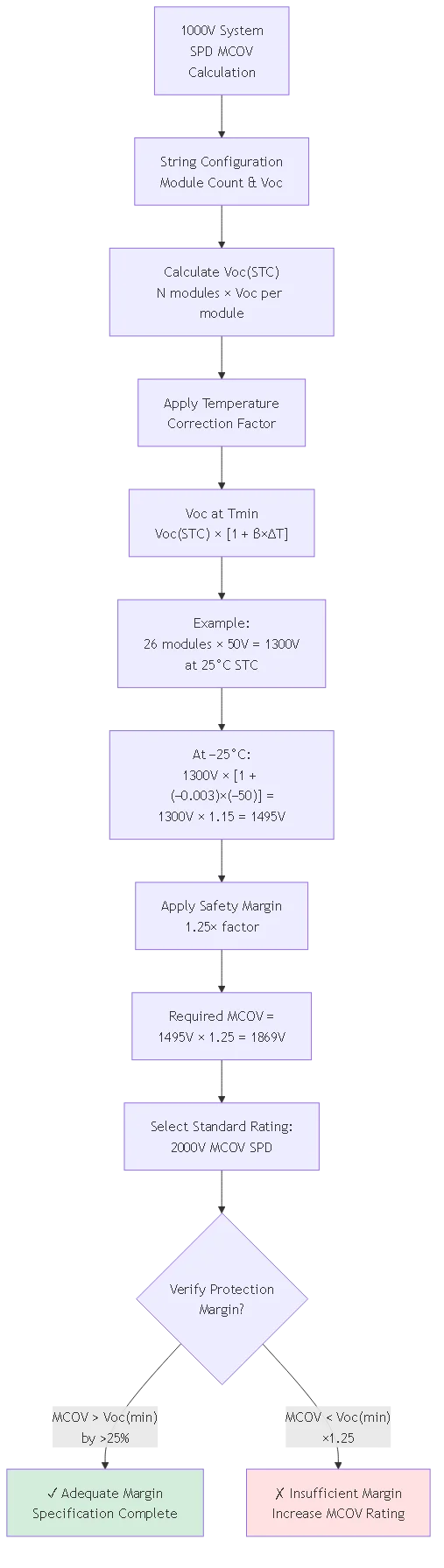
Temperature compensation significantly affects maximum voltage. Photovoltaic module open-circuit voltage increases approximately 0.27-0.35%/°C below standard test temperature. Calculate temperature-compensated Voc using: Voc(T) = Voc(STC) × [1 + β × (T − 25°C)] where β is temperature coefficient (typically −0.0030 to −0.0035/°C) and T is minimum expected temperature. For system with 1300V Voc(STC) operating at −25°C: Voc(−25°C) = 1300V × [1 + (−0.0030) × (−25°C − 25°C)] = 1300V × 1.15 = 1495V.
Apply safety margin accounting for measurement uncertainties, module manufacturing tolerances (typically ±3% on Voc), and potential overvoltage from partial shading or module mismatch. Required MCOV = Voc(min temp) × 1.25 safety factor. For example calculated above: MCOV = 1495V × 1.25 = 1869V minimum. Round to next standard rating: specify 2000V MCOV SPD providing adequate margin above calculated 1869V requirement ensuring SPD never operates near voltage rating limits.
Voltage protection level for 1000V DC SPDs typically ranges 2500-3500V depending on MCOV rating, protection element technology, and equipment insulation coordination requirements. Lower VPL provides better equipment protection but requires larger, more expensive varistor elements and tighter manufacturing tolerances. Optimal VPL selection balances protection effectiveness against cost and physical size constraints.
Equipment insulation coordination principle: SPD voltage protection level plus ground lead voltage drop must not exceed 70% of protected equipment impulse withstand voltage providing adequate safety margin. For inverter rated 8000V impulse withstand: maximum allowable SPD let-through voltage = 8000V × 0.70 = 5600V. Subtracting ground lead contribution (assume 500V for 200mm lead during 10kA surge): maximum SPD VPL = 5600V − 500V = 5100V. This analysis shows 3500V VPL specification provides comfortable 1600V margin below maximum allowable level.
High-voltage SPD manufacturers often publish VPL at multiple test current levels showing protection performance across surge range. Typical specification format: VPL at nominal discharge current In (e.g., “VPL = 3200V at 20kA”) plus VPL at maximum discharge current Imax = 2×In (e.g., “VPL = 3600V at 40kA”). The VPL increase with current reflects voltage-dependent resistance characteristic of varistor elements requiring higher voltage to conduct higher current. Use VPL at Imax for worst-case protection coordination analysis.
⚠️ Important : Never specify 1000V SPD based solely on nominal voltage rating without calculating actual MCOV requirement from temperature-compensated Voc. Undersized MCOV causes continuous voltage stress degrading SPD varistor elements and dramatically shortening service life. Failed SPDs provide no protection leaving expensive inverters ($50,000-200,000 for utility-scale units) vulnerable to surge damage.
1000V system surge energy requirements differ from 600V installations due to proportionally higher induced voltages and longer conductor runs collecting more electromagnetic energy. Lightning electromagnetic pulse (LEMP) induced voltage is proportional to conductor loop area—1000V strings covering 26 modules span approximately 50% greater length than equivalent 600V strings (18 modules) creating 50% larger loop area and correspondingly higher induced surge voltages.
Type 1 SPDs become increasingly important at 1000V for array-origin protection where direct lightning attachment remains possible despite elevated system voltage. Calculate specific energy per conductor from: E = 0.5 × L × I² where L is conductor inductance and I is surge current. For 50-meter DC circuit (inductance ~75μH) conducting 25kA direct-strike partial current: E = 0.5 × 75μH × (25,000A)² = 23kJ per conductor. This energy level requires Type 1 SPD capability—Type 2 devices typically handle maximum 8-12kJ insufficient for direct strike protection.
Coordinated Type 1 + Type 2 topology provides optimal protection for utility-scale 1000V installations. Install Type 1 SPDs (Iimp ≥ 25kA, 10/350μs) at array origins or main combiner outputs where direct strike energy might appear. Coordinate with Type 2 SPDs (In = 20-40kA, 8/20μs) at inverter DC inputs separated by minimum 10-meter conductor run providing natural decoupling inductance. This two-stage approach balances high-energy capability at exposed locations with cost-effective protection at equipment locations.
Nominal discharge current rating for 1000V Type 2 SPDs should range 20-40kA per pole depending on lightning exposure assessment and coordination with upstream Type 1 devices. Higher ratings extend service life in high-lightning-activity regions but increase SPD cost and physical size. Utility-scale installations justify higher ratings given substantial equipment replacement costs ($50,000-200,000 per inverter) and revenue losses during unplanned downtime exceeding direct equipment costs.
Type 1 SPD impulse current (Iimp) ratings for 1000V array origins typically specify 25-50kA per pole. Calculate required Iimp from lightning protection level (LPL) analysis per IEC 62305-2. For LPL III protection (typical for commercial/industrial structures): maximum expected partial lightning current flowing through SPD location = 50kA (10/350μs waveform). Select SPD with Iimp ≥ expected current: specify 50kA Type 1 providing adequate margin. Higher-exposure locations (LPL I or II) require proportionally higher ratings up to 100kA.
Multi-inverter installations benefit from current division reducing per-inverter SPD rating requirements. Array field with total short-circuit current 800A feeding four parallel 200A inverters can specify individual inverter SPDs rated for 200A circuit plus surge margin rather than full 800A array capability. This parallel division allows use of lower-rated SPDs at individual inverter inputs while upstream array SPD handles combined surge current from all strings.
| Installation Location | SPD Classification | Current Rating | MCOV @ 1000V | Typical VPL |
|---|---|---|---|---|
| Array Origin / Main Combiner | Type 1 | 25-50kA (Iimp) | 1500-2000V | 2800-3500V |
| Inverter DC Input (Coordinated) | Type 2 | 20-40kA (In) | 1500-2000V | 2500-3200V |
| Inverter Input (Standalone) | Type 1+2 Hybrid | 25kA Iimp + 40kA In | 1500-2000V | 2800-3500V |
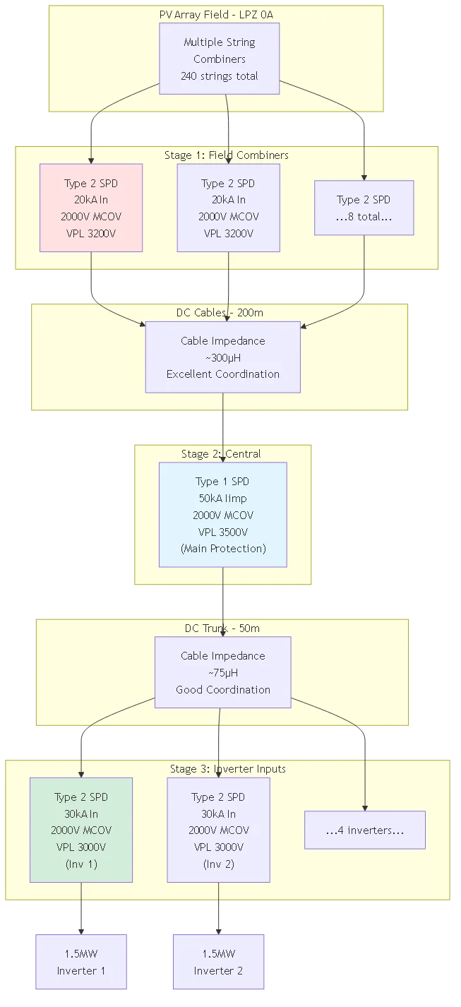
Utility-scale 1000V installations benefit from three-stage SPD coordination creating defense-in-depth protection: Stage 1 at array field combiners, Stage 2 at central combiner or recombiner stations, Stage 3 at individual inverter DC inputs. Each stage intercepts surge energy appropriate to its location reducing cumulative stress on downstream protection and equipment.
Stage 1 – Array Field Combiners:
Install Type 2 SPDs (In = 20-30kA) at individual string combiners throughout array field. These SPDs intercept string-level surges from direct strikes to specific array sections or induced transients in local string conductors. Distributed Stage 1 protection prevents surge energy coupling between parallel array sections through common DC infrastructure.
Stage 2 – Central Recombiner/Collection Point:
Install robust Type 1 SPDs (Iimp = 50kA) at central collection point where multiple array field outputs combine before routing to inverter station. Stage 2 location represents maximum expected surge energy concentration requiring highest SPD capability. Separation from Stage 1: typically 100-500 meters providing substantial conductor impedance (150-750μH) ensuring excellent coordination between stages.
Stage 3 – Inverter DC Inputs:
Install Type 2 SPDs (In = 30-40kA) immediately before each inverter DC input terminals. Stage 3 provides final protection for sensitive power electronics against residual transients bypassing upstream protection. Separation from Stage 2: minimum 15-20 meters (22-30μH impedance) ensuring adequate decoupling for independent operation.
Calculate coordination impedance between SPD stages ensuring adequate decoupling preventing simultaneous conduction. Required minimum impedance depends on SPD voltage protection levels and expected surge current rise rates. Use formula: Zmin = (VPL_upstream − VPL_downstream) / (di/dt) where VPL values are protection levels and di/dt is surge current rise rate.
Example calculation for Stage 1 to Stage 2 coordination:
– Stage 1 VPL = 3200V (Type 2, 20kA)
– Stage 2 VPL = 3500V (Type 1, 50kA)
– Expected di/dt = 10kA/μs (worst case)
– Zmin = (3500V − 3200V) / (10kA/μs) = 300V / 10kA/μs = 30μH
For typical DC cable inductance 1.5μH/meter, required separation = 30μH / 1.5μH/m = 20 meters minimum. Actual array field installations typically provide 100+ meters providing 150μH impedance (5× minimum) ensuring robust coordination with substantial margin.
When physical separation is insufficient, install discrete decoupling inductors artificially creating required impedance. High-voltage decoupling inductors for 1000V systems typically specify 20-50μH inductance rated for continuous DC current plus short-duration surge current without saturation. These inductors must withstand system voltage (1000V+ rating) and exhibit low DC resistance (< 1mΩ) minimizing power losses during normal operation.
🎯 Pro Tip : Model three-stage coordination using SPICE simulation or specialized surge protection analysis software before finalizing specifications. Simulation reveals voltage stress at each protection stage under various surge scenarios identifying potential coordination failures or inadequate protection margins. Software tools like EMTP-ATP or PSpice allow accurate modeling of distributed protection systems accounting for conductor impedance, SPD nonlinear characteristics, and equipment response.
1000V DC systems present significant arc flash hazards during SPD installation and maintenance requiring comprehensive hazard assessment and appropriate personal protective equipment (PPE). DC arc flash energy calculations follow IEEE 1584 methodology adapted for DC systems: Earc = V × I × t / d² where V is system voltage, I is available fault current, t is arc duration, and d is worker distance. Higher 1000V voltage dramatically increases incident energy compared to 600V equivalents.
Calculate available fault current from parallel string configuration: total array short-circuit current equals sum of individual string Isc values. For 240-string array with 12A per string: available fault current = 240 × 12A = 2880A. At 1000V with 0.5-second arc duration (typical disconnect clearing time) and 450mm worker distance: Earc ≈ 15 cal/cm² requiring NFPA 70E Category 3 PPE (minimum 25 cal/cm² rated arc flash suit).
Implement safety procedures reducing arc flash exposure:
– Verify complete de-energization using voltage detectors rated for 1000V+ DC
– Cover array modules with opaque tarps during installation reducing generated voltage
– Install temporary shorting jumpers across combiner busbars after verification of zero voltage
– Maintain approach boundaries per NFPA 70E Table 130.4(E)
– Use insulated tools rated 1000V minimum for all work near energized parts
IEC 60664-1 and UL 508A specify increased clearance and creepage distances for 1000V equipment preventing flashover under normal and transient overvoltage conditions. Minimum clearance (air gap) for 1000V equipment in Pollution Degree 2 environment (typical solar installation): 14mm for basic insulation, 28mm for reinforced insulation. SPD installations must maintain these clearances between energized parts and grounded enclosures, adjacent conductors, or accessible surfaces.
Creepage distance (surface path along insulating material) requirements exceed clearance due to surface contamination risks. For 1000V in Pollution Degree 2: minimum 20mm creepage for basic insulation, 40mm for reinforced insulation. SPD terminal blocks and conductor entry points must provide adequate creepage preventing tracking failures in dusty or humid environments typical of outdoor combiner installations.
Indoor vs. outdoor SPD enclosures affect pollution degree and corresponding clearance requirements. Indoor inverter station SPDs may use Pollution Degree 2 specifications while outdoor array field SPDs require Pollution Degree 3 (conductive pollution) increasing clearances to 20mm basic, 40mm reinforced. Specify SPD enclosure ratings appropriately: NEMA 3R minimum for outdoor, NEMA 1 acceptable for clean indoor inverter rooms.
High-voltage spark gap hybrid SPDs combine gas discharge tube (GDT) technology with metal oxide varistors delivering superior performance for 1000V applications. The GDT handles initial high-current surge phase (up to 100kA capability) while MOV provides fast voltage clamping during GDT ionization delay and protects against low-amplitude transients insufficient to trigger GDT activation.
Three-electrode triggered spark gap designs improve response time compared to conventional two-electrode GDTs. Triggered gaps use auxiliary electrode sensing voltage rise and actively ionizing main gap gas when threshold is exceeded. Response time improves from 100-300ns (passive GDT) to 20-50ns (triggered gap) approaching MOV-only response while retaining GDT’s high current capability and long service life. These hybrid designs cost 30-50% more than MOV-only SPDs but provide optimal protection for expensive utility-scale inverters.
Silicon carbide (SiC) varistor technology offers advantages for 1000V SPDs compared to traditional zinc oxide (ZnO) varistors. SiC exhibits higher thermal conductivity (120 W/m·K vs 25 W/m·K for ZnO) allowing better heat dissipation during surge events and continuous operation. Higher operating temperature capability (175°C vs 85°C) suits harsh outdoor combiner environments. Lower capacitance (<50pF vs 200-500pF) reduces coupling of high-frequency surge components into protected circuits.
Utility-scale installations increasingly specify SPDs with integrated monitoring and diagnostics enabling remote condition assessment and predictive maintenance. Smart SPD technology includes embedded microcontrollers measuring leakage current, varistor degradation, surge event counting, and remaining service life estimation. These parameters transmit via Modbus RTU, PROFINET, or proprietary protocols to central SCADA systems.
Monitored parameters indicating SPD condition:
- Leakage current trend: Gradually increasing leakage indicates varistor degradation approaching failure
- Surge event counter: Tracks number and magnitude of surge activations consuming SPD capacity
- Temperature monitoring: Excessive temperature suggests poor connections or overloaded protection
- Résistance de l'isolation: Decreasing resistance indicates moisture ingress or tracking failures
- Remaining capacity: Algorithm estimates remaining surge energy capacity based on event history
Preventive maintenance triggers reduce unplanned downtime. Configure SCADA system to generate maintenance work orders when SPD parameters exceed thresholds: leakage current >200% of baseline, surge event count >50, temperature >60°C, or remaining capacity <20%. Proactive SPD replacement before failure prevents equipment damage and associated revenue losses exceeding SPD replacement cost.
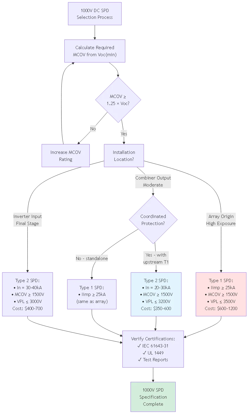
For 1000V nominal photovoltaic systems, specify minimum 1500V MCOV accounting for temperature-compensated open-circuit voltage. Calculate required MCOV from: string Voc at minimum temperature × 1.25 safety factor. Typical 1000V system with 26 modules (50V each) delivers 1300V Voc at standard conditions. At −25°C with temperature coefficient −0.003/°C: Voc = 1300V × 1.15 = 1495V. Required MCOV = 1495V × 1.25 = 1869V minimum—specify 2000V MCOV SPD providing adequate margin.
Higher MCOV ratings (2000V vs 1500V) cost 20-30% more but provide essential protection against continuous voltage stress degrading varistor elements. Undersized MCOV represents common specification error causing premature SPD failure through chronic overvoltage exposure. The incremental cost difference ($100-150 per SPD) is negligible compared to inverter replacement costs ($50,000-200,000) if inadequate protection fails.
Regional climate affects MCOV requirements significantly. Cold-climate installations (Canada, Nordic countries, mountain sites) experience lower ambient temperatures increasing module Voc requiring higher MCOV ratings. Desert installations despite extreme heat focus on cold-morning startup conditions when modules reach minimum temperature after overnight cooling potentially dropping below 0°C even in hot climates.
Type 2 SPDs suffice for 1000V inverter DC inputs when coordinated with upstream Type 1 protection at array origins or main combiners. The upstream Type 1 SPD intercepts direct-strike energy while Type 2 at inverter handles residual transients after conductor impedance attenuation. Specify Type 2 with In = 30-40kA, MCOV ≥ 1500V, and VPL ≤ 3200V for coordinated inverter protection. Ensure minimum 10-15 meter separation between Type 1 and Type 2 stages providing adequate decoupling inductance.
Standalone inverter protection without upstream Type 1 coordination requires hybrid Type 1+Type 2 SPD or robust Type 1-only device. Hybrid designs combine Type 1 energy handling with Type 2 response speed providing comprehensive single-point protection. Type 1-only requires careful VPL selection ensuring adequate equipment protection margin—some Type 1 devices specify VPL 3500-4000V requiring verification against inverter 8000V insulation rating.
The coordination decision balances cost versus protection reliability. Two-stage coordinated approach (Type 1 array + Type 2 inverter) costs $950-1800 total but provides defense-in-depth. Single-stage Type 1 hybrid at inverter costs $800-1200 but eliminates upstream protection. For utility-scale installations protecting multi-megawatt inverters, specify coordinated two-stage approach—marginal additional cost is insignificant versus potential equipment loss.
Calculate DC arc flash incident energy using adapted IEEE 1584 methodology: Earc = V × I × t / (4π × d²) where V is system voltage (1000V), I is available fault current (total array Isc), t is arc duration (disconnect clearing time), and d is worker distance (typically 450mm per NFPA 70E). For 240-string array with 12A per string: I = 2880A. With 0.5s clearing time: Earc = 1000V × 2880A × 0.5s / (4π × 0.45²m²) ≈ 15 cal/cm².
This 15 cal/cm² incident energy requires NFPA 70E Hazard Risk Category 3 PPE: minimum 25 cal/cm² arc-rated clothing, arc-rated face shield, arc-rated gloves, and hearing protection. Most utility-scale installations specify Category 4 PPE (40 cal/cm²) providing additional safety margin for calculation uncertainties and worst-case scenarios. Arc flash labels must display calculated incident energy and required PPE category per NFPA 70E 130.5.
Reduce arc flash exposure through engineered controls: install current-limiting fuses (reduce available fault current), use remote racking systems (increase worker distance), implement zone-selective interlocking (decrease clearing time), and require voltage verification before work. Some installations mandate covering array modules during SPD maintenance reducing generated voltage to near-zero eliminating arc flash hazard entirely.
Absolutely not—using 600V-rated SPDs in 1000V systems violates electrical codes, insurance requirements, and basic safety principles. SPD MCOV rating must exceed system maximum voltage by substantial margin (typically 1.25×). Installing 600V SPD (typical MCOV 850-1000V) in 1000V system (Voc 1100-1400V) creates continuous overvoltage stress causing rapid varistor degradation and likely SPD failure within days or weeks.
Failed SPDs in 1000V systems pose serious safety hazards: varistor thermal runaway can generate sufficient heat to ignite nearby combustible materials creating fire risk. SPD short-circuit failures may not clear through overcurrent protection if rated inadequately for system fault current allowing sustained arc fault. Explosion of overstressed SPD enclosure projects hot debris potentially causing injury to personnel or damage to adjacent equipment.
Temporary operation without SPD protection is safer than using inadequately rated SPDs. Unprotected systems remain vulnerable to surge damage but don’t introduce additional failure modes from overstressed protection components. If proper 1000V SPDs are unavailable, implement alternative protection: disconnect arrays during thunderstorm activity, install temporary lightning masts providing shielding, or delay system commissioning until correct SPDs are obtained and installed.
1000V SPD service life in utility-scale installations typically ranges 5-10 years depending on lightning exposure, surge event frequency, and SPD quality. High-exposure sites (isokeraunic level >40 thunderstorm days/year) may require replacement every 3-5 years while low-exposure locations achieve 10+ years. Service life correlates with cumulative surge energy absorption rather than calendar time—SPDs in high-activity regions absorb rated capacity faster requiring earlier replacement.
Manufacturers specify total energy absorption capacity (measured in kJ) representing maximum cumulative surge energy SPD handles before requiring replacement. Typical Type 2 SPD (In = 30kA) for 1000V application specifies 150-250kJ total capacity. Each 20kA surge event (8/20μs waveform) consumes approximately 40kJ capacity. After 4-6 major surge events, SPD approaches end of useful life requiring replacement before protective capability degrades below acceptable level.
Proactive replacement strategies optimize protection reliability versus cost. Calendar-based replacement every 8-10 years provides conservative approach ensuring protection remains effective throughout expected service life. Condition-based replacement using annual testing measuring VPL degradation and leakage current trends allows extended operation of lightly-stressed SPDs while identifying degraded devices requiring early replacement. Smart SPDs with integrated monitoring enable data-driven replacement decisions optimizing maintenance spending.
Complete 1000V SPD protection system for utility-scale installation costs $5,000-15,000 per megawatt depending on protection strategy, equipment quality, and installation complexity. Single-stage protection (Type 1 at inverter inputs only) costs $4,000-6,000 per inverter (1.5-2MW) for devices plus installation. Two-stage coordinated protection (Type 1 array + Type 2 inverter) increases cost to $6,000-9,000 per inverter but provides superior protection justifying incremental expense for critical revenue-generating assets.
Component cost breakdown for 1.5MW inverter protection:
- Type 1 SPD (main array): $800-1500 per device
- Type 2 SPD (inverter input): $400-800 per device
- Installation labor: $500-1000 per location (mounting, wiring, testing)
- Enclosure modifications: $200-500 (DIN rail, busbar, terminals)
- Testing and commissioning: $300-600 (surge testing, documentation)
- Total per inverter: $2,200-4,400 single stage, $3,400-6,200 two-stage
Annual maintenance costs approximately 5-10% of initial installation covering quarterly inspections, annual electrical testing, and periodic SPD replacement (every 5-8 years). For 10MW installation: initial SPD investment $50,000-90,000, annual maintenance $5,000-9,000. This protection investment represents 0.5-0.9% of total project cost ($10-12M) providing essential insurance against surge damage and unplanned downtime.
Essential certifications for 1000V DC SPDs include IEC 61643-31 compliance verified by accredited testing laboratory (TÜV, VDE, CSA, Intertek) and UL 1449 Fourth Edition listing for North American installations. IEC 61643-31 establishes standardized testing protocols for PV surge protection including 10/350μs (Type 1) and 8/20μs (Type 2) waveform testing, thermal stability verification, and short-circuit interruption capability. UL 1449 adds safety requirements preventing SPD failures from creating fire or shock hazards.
Additional valuable certifications include IEC 62109-2 verifying SPD compatibility with inverter requirements, UL 1741 for grid-connected systems, and regional marks (CE for Europe, CCC for China, PSE for Japan) when required by installation location. Some utility interconnection agreements mandate specific testing beyond minimum certifications such as salt spray resistance for coastal installations or seismic qualification for earthquake-prone regions.
Request manufacturer test reports documenting actual measured performance rather than relying solely on certification marks. Test reports reveal VPL at multiple current levels, follow current interruption capability, aging test results showing performance after 15 surge applications, and thermal stability data. These details indicate quality differences between manufacturers meeting identical minimum certification requirements—premium SPDs may exceed requirements by 50-100% providing additional performance margin.
Proper 1000V DC surge protective device selection requires comprehensive analysis of high-voltage system characteristics, multi-stage protection coordination, and utility-scale application requirements. Understanding MCOV calculation methodology, Type 1 vs Type 2 selection criteria, voltage protection level coordination, and advanced SPD technologies enables engineers to design effective protection systems for multi-megawatt photovoltaic installations.
Principaux enseignements :
1. Calculate MCOV from temperature-compensated Voc multiplied by 1.25 safety factor—typical 1000V systems require 1500-2000V MCOV SPDs
2. Specify Type 1 SPDs (Iimp ≥ 25kA) at array origins coordinated with Type 2 SPDs (In = 30-40kA) at inverter inputs for optimal defense-in-depth
3. Implement three-stage protection for utility-scale installations distributing surge energy across multiple SPD locations reducing stress on each component
4. Conduct arc flash hazard assessment—1000V systems typically require Category 3-4 PPE (25-40 cal/cm²) for safe SPD installation and maintenance
5. Consider advanced SPD technologies including triggered spark gaps, silicon carbide varistors, and integrated monitoring for critical utility-scale applications
High-voltage photovoltaic surge protection represents significant engineering challenge requiring careful specification, proper coordination, and ongoing maintenance. The substantial investment in 1000V SPD systems ($5,000-15,000 per MW) provides essential insurance protecting multi-million dollar equipment and preventing revenue losses from unplanned downtime exceeding protection system costs.
Ressources connexes :
- DC SPD Type 2 Specifications: IEC 61643 Classification
- DC SPD Connection Diagrams: Multi-Stage Coordination
- PV Combiner Box Components for 1000V Systems
Ready to specify comprehensive 1000V SPD protection for your utility-scale solar projects? Contact our high-voltage protection engineering team for lightning risk assessment, multi-stage coordination analysis, arc flash hazard calculation, and custom SPD system design optimized for your installation requirements and budget.
Dernière mise à jour : Novembre 2025
Auteur : L'équipe technique de SYNODE
Révisé par : High-Voltage Protection Engineering Department