Adresse
304 North Cardinal
St. Dorchester Center, MA 02124
Heures de travail
Du lundi au vendredi : de 7h00 à 19h00
Le week-end : 10H00 - 17H00
Adresse
304 North Cardinal
St. Dorchester Center, MA 02124
Heures de travail
Du lundi au vendredi : de 7h00 à 19h00
Le week-end : 10H00 - 17H00


A 4 string PV combiner box serves small to medium commercial solar installations in the 20-30 kW range, consolidating four independent string circuits through carefully designed busbar layouts that optimize current distribution and thermal performance. Unlike residential 2-3 string combiners where component placement flexibility exists, 4 string configurations require deliberate busbar geometry preventing uneven current sharing and hot spot formation. Proper layout design ensures balanced current flow, minimizes voltage drop, and facilitates maintenance access throughout the system’s 25+ year lifespan.
The transition from 3 to 4 strings introduces complexity beyond simply adding another fuse position. Four parallel current paths create opportunities for circulating currents, unequal impedance distribution, and thermal imbalances if busbar geometry isn’t optimized. Understanding current division principles, conductor skin effect at DC, and NEC clearance requirements enables designing combiner layouts that perform reliably under full load while remaining serviceable for troubleshooting and component replacement.
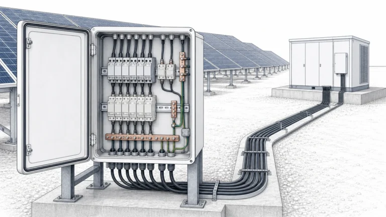
Small commercial buildings with 20-30 kW rooftop arrays naturally divide into four distinct zones based on roof sections, HVAC equipment locations, and structural constraints. A 4 string combiner consolidates these zones into a single managed circuit, simplifying inverter connections and monitoring infrastructure. Each string represents 5-7.5 kW of capacity, matching typical commercial panel wattages and string voltages within standard 600-1000V equipment ratings.
Warehouse and light industrial facilities often feature four roof planes—north, south, east, and west—each supporting a PV string. The 4 string combiner enables centralized protection and monitoring despite disparate array orientations. String-level MPPT at the inverter optimizes power extraction from differently oriented arrays, with the combiner providing electrical consolidation and protection without interfering with independent MPPT operation.
Agricultural applications including barns, equipment sheds, and processing facilities use 4 string combiners for distributed 20-30 kW systems. These installations frequently face harsh environmental conditions—ammonia, hydrogen sulfide, and high humidity—requiring robust NEMA 4X enclosures and corrosion-resistant busbar materials. The 4-string capacity matches agricultural electrical loads while remaining below utility interconnection thresholds requiring expensive grid upgrades.
Multi-family residential buildings and small apartment complexes deploy 4 string systems sized to offset common area electrical consumption. Rooftop arrays spanning 20-25 kW feed single inverters, with individual string monitoring enabling maintenance personnel to identify underperforming sections. The 4 string configuration provides granular visibility into system performance without the complexity of larger 6-8 string industrial combiners.
💡 Aperçu clé : Four-string systems represent the crossover point between residential simplicity and commercial complexity. Proper busbar layout becomes critical—whereas 2-3 string combiners tolerate basic linear busbar designs, 4+ strings demand engineered layouts preventing current imbalance and ensuring even thermal distribution.
| System Configuration | String Power | Combined Output | Application typique |
|---|---|---|---|
| 4×5kW Strings | 12 panneaux × 400W | 20 kW, 35A @ 600V | Small commercial, retail |
| 4×6kW Strings | 14 panels × 450W | 24 kW, 40A @ 650V | Office building, church |
| 4×7kW Strings | 16 panels × 450W | 28 kW, 42A @ 700V | Warehouse, light industrial |
| 4×8kW Strings | 18 panneaux × 450W | 32 kW, 45A @ 750V | Agricultural, multi-family |
Symmetric busbar geometry ensures equal impedance from each string connection to the main breaker output, preventing current imbalance between parallel strings. A linear busbar with connections at positions 1, 2, 3, and 4 creates unequal path lengths—String 1 travels through the entire busbar length while String 4 connects near the output, creating impedance mismatch. This imbalance causes uneven current sharing where lower-impedance strings carry disproportionate current.
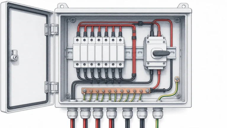
The H-configuration busbar design provides optimal symmetry for 4 string applications. Two horizontal busbars (positive and negative) connect to a central vertical distribution section where the main breaker mounts. String fuses connect at equal distances from the center point, ensuring balanced impedance. This geometry maintains path length differences under 10%, translating to current imbalance under 2-3% at rated load.
T-configuration layouts suit rectangular enclosures where space constraints prevent full H-geometry. The main busbar runs vertically with two string connections on each side, spaced equally. While not perfectly symmetric, properly designed T-layouts achieve impedance matching within 5-8%, acceptable for most commercial applications. This configuration simplifies conductor routing in tight enclosures.
Busbar cross-sectional area must handle combined string current plus 25% safety margin per NEC 690.8(A). Four strings at 10-11A each produce 40-44A combined, requiring busbar capacity of 50-55A minimum. Standard 1/4″ × 2″ (6.4mm × 50.8mm) copper bar rates 175-225A continuous, providing substantial margin ensuring cool operation even in high-ambient temperature environments reaching 50-60°C internal.
⚠️ Important : Never use a simple linear busbar with four connections in series. This creates a 3:1 impedance ratio between first and last string positions, causing the end strings to carry 15-20% more current than center strings. Unbalanced current accelerates busbar heating and can trip breakers prematurely.
Current density in copper busbars should not exceed 1.5-2.0 A/mm² for reliable long-term operation without excessive temperature rise. A 1/4″ × 2″ busbar has 161.3 mm² cross-section, handling 240-320A theoretically. In practice, limit loading to 125-150A (0.8-0.9 A/mm²) accounting for skin effect, termination resistance, and ambient temperature variations. This conservative sizing prevents hotspots at connections where current density concentrates.
Connection point resistance dominates thermal performance in properly sized busbars. Each fuse holder, lug, and bolt interface introduces 50-200 microohms resistance. With four string connections each carrying 10A, a 100 microohm connection generates 10W heat (I²R = 10² × 0.0001 = 1W per amp squared). Poor connections with 500+ microohm resistance generate 50W, creating dangerous hot spots. Proper torque specifications (typically 12-18 Nm for M6 hardware) ensure low-resistance interfaces.
Enclosure ventilation prevents heat accumulation from I²R losses in busbars, fuses, and breaker contacts. NEMA 4X enclosures with gasket seals trap heat, potentially raising internal temperature 20-40°C above ambient. For outdoor installations in hot climates, internal temperatures may reach 80-90°C, requiring component derating. Adding ventilated enclosure designs with rain-protected vents maintains lower temperatures while preserving weather protection.
Thermal imaging during commissioning and annual maintenance verifies balanced current distribution and identifies degraded connections before failure. All four string input connections should exhibit similar temperatures within 5-10°C. Significant temperature differences indicate unequal current sharing from asymmetric busbar layout or one string producing less current due to shading or module degradation. Temperature monitoring provides early warning of developing problems.
| Busbar Configuration | Impedance Balance | Current Imbalance | Thermal Performance |
|---|---|---|---|
| Linear (Poor Design) | 3:1 ratio | 15-20% | Hot spots at end positions, uneven heating |
| T-Configuration | 1.2:1 ratio | 5-8% | Acceptable, slight temperature variation |
| H-Configuration (Optimal) | 1.05:1 ratio | 2-3% | Excellent, uniform temperature distribution |
| Radial (Premium) | 1.02:1 ratio | 1-2% | Superior, minimal temperature variation |
Fuse sizing follows NEC 690.9(B) requiring 1.56× string Isc minimum. For 10.5A Isc strings, minimum fuse rating equals 16.38A, requiring standard 20A fuses. However, string monitoring systems and reduced module Isc in newer high-efficiency panels may permit 15A fuses. Always verify calculations against specific module datasheets—some 450W panels specify 11.5A Isc requiring 18A minimum (rounded to 20A standard), while others rate 10A Isc permitting 15.6A minimum (use 15A or 20A standard).
Main circuit breaker sizing accounts for combined four-string output plus 125% safety factor. Four strings at 10.5A produce 42A combined, requiring breaker rating of 52.5A minimum. Standard 63A or 80A breakers satisfy this requirement. Select 63A for better overload protection in systems where overloading is unlikely, or 80A for installations with potential for temporary overcurrent during edge-of-cloud effects or module temperature swings.
Busbar selection balances current capacity, thermal performance, and cost. For 42A continuous load, minimum busbar capacity is 52.5A, but best practice specifies 100-150A rated bars providing 2-3× margin. This oversizing limits temperature rise to 10-15°C above ambient under full load, extending busbar life and preventing thermal degradation of insulation. Use 1/4″ × 2″ copper bar for 40-50A systems, 1/4″ × 3″ for 50-70A applications.
Output conductor sizing from combiner to inverter follows NEC 690.8(B) requiring 125% of maximum current capability. For 42A output, conductors must handle 52.5A continuous. NEC Table 310.16 shows 8 AWG copper at 90°C rates 55A, satisfying the requirement. However, if conduit runs through hot attics or sunny roof sections, apply temperature derating—in 70°C ambient, 8 AWG derates to 45A, requiring upgrade to 6 AWG (75A derated to 61A at 70°C ambient).
NEMA 4X stainless steel enclosures provide optimal protection for commercial 4 string combiners, featuring gasket-sealed doors and corrosion-resistant construction surviving 20+ years in harsh environments. Minimum internal dimensions of 14″×14″×8″ (350×350×200mm) accommodate H-configuration busbar layouts with 6″ clearance to enclosure walls per NEC 110.26. Larger 16″×16″×10″ enclosures suit installations with string monitoring terminals or future expansion provisions.
Fiberglass-reinforced polyester (FRP) enclosures offer lightweight alternative to stainless steel at 60-70% of the cost. FRP provides excellent UV resistance, chemical resistance in agricultural/industrial environments, and electrically non-conductive mounting surface. However, FRP requires careful attention to busbar mounting—use insulated standoffs rather than direct mounting to enclosure backplate ensuring adequate electrical clearance.
Aluminum NEMA 4X enclosures balance cost and performance for moderate environments without heavy chemical exposure. Powder-coated aluminum provides corrosion resistance while maintaining lighter weight than stainless steel. Coastal installations within 1-2 miles of saltwater should use stainless steel or FRP instead of aluminum to prevent corrosion from salt spray and airborne chlorides affecting component reliability.
Ventilation considerations affect enclosure selection for high-ambient installations. Standard NEMA 4X enclosures with gasket seals trap heat, potentially raising internal temperature 30-40°C above ambient. For desert or tropical installations, specify enclosures with rain-protected vents or heat exchangers maintaining NEMA 4X rating while enabling heat dissipation. Alternative approach uses oversized enclosures (18″×20″) providing greater thermal mass and surface area for passive cooling.
🎯 Pro Tip : Specify enclosures with removable/reversible mounting plates for combiner pre-assembly. Mount all components on the plate in your shop, wire and test, then install the complete assembly into the enclosure on-site. This approach reduces field labor by 40-60% and improves installation quality through controlled assembly conditions.
Type 2 SPD protection at 4 string combiners requires enhanced specifications compared to residential applications due to higher system value and lightning exposure of larger roof-mounted arrays. Specify SPDs with In=40 kA minimum, Imax=80 kA for installations in high-lightning regions (>30 thunderstorm days/year). MCOV rating must exceed system maximum Voc—for 700V systems, use 1200V MCOV minimum; 900V systems require 1500V MCOV SPDs.
Dual SPD configuration provides redundant protection for high-value commercial installations. Install primary SPD on the combiner output between main breaker and inverter feed, and secondary SPD on the busbar between string inputs and main breaker. This two-stage approach ensures protection even if one SPD fails degraded. Coordinate SPD Up levels: secondary SPD Up=3.5 kV, primary Up=3.0 kV, creating staged protection cascade.
SPD grounding conductor sizing follows NEC 690.35(C) requiring #10 AWG minimum for circuits under 60A. However, best practice for commercial 4-string installations uses #6 AWG grounding conductors minimizing inductance and voltage drop during surge events. Route SPD ground conductor directly to ground bus in shortest path avoiding loops—each additional foot of conductor length adds 30-50V to effective Up during fast-rise surges.
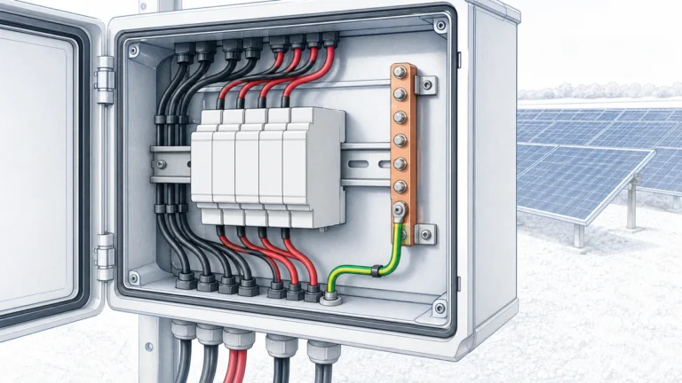
Ground bus sizing accommodates equipment grounding conductor (EGC), array frame grounding, SPD ground connections, and negative busbar bonding jumper in negative-grounded systems. Use 1/4″×2″ copper ground bus matching power busbar dimensions, providing sufficient connection points for all ground terminations. Locate ground bus centrally in enclosure enabling short, direct connections from all components.
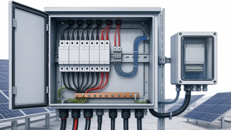
Commercial 4 string combiners benefit from string-level current monitoring enabling remote fault detection and performance optimization. Hall-effect current sensors (CTs) on each string input measure real-time current with 0.5-1% accuracy. Digital monitoring systems communicate via Modbus RTU or RS-485 protocols to SCADA platforms, providing visibility into individual string performance without site visits.
CT sensor selection depends on string current magnitude. For 10-12A rated strings, specify 20A or 30A CTs providing measurement range for temporary overcurrents during edge-of-cloud enhancement. Split-core CTs enable installation without breaking string conductors, simplifying retrofit monitoring additions. Mount CTs on fuse input conductors inside the combiner enclosure, protecting sensors from weather exposure.
Monitoring terminal blocks dedicate connections for CT signals, voltage sense leads, and communications wiring separate from power circuits. Use DIN-rail mounted terminal strips with screw or spring terminals preventing vibration loosening. Color-code monitoring circuits distinctly from power wiring—gray or blue for CT signals, white for voltage sense, yellow/green for communications. Document terminal assignments on interior enclosure labels.
Power supply for monitoring systems typically derives from auxiliary AC power (120V) or 24VDC battery backup systems. Avoid parasitic DC-DC converters on the main PV circuits—these introduce failure modes and voltage drop in power production circuits. Dedicated monitoring power ensures continuous operation enabling nighttime communications and alarm functionality when PV production ceases.
Busbar torque specifications prevent loose connections causing resistance heating and arc faults. Copper busbar connections typically require 12-18 Nm (106-159 lb-in) for M6 hardware, 20-25 Nm for M8 hardware. Use calibrated torque wrenches—not impact drivers or adjustable wrenches. Over-torquing damages threads and deforms washers, while under-torquing leaves high-resistance joints. Record torque values on installation documentation for future maintenance reference.
Lock washers or thread-locking compound prevents vibration loosening of electrical connections. Split lock washers work adequately for indoor installations with minimal vibration. Outdoor and agricultural installations subject to wind-induced vibration benefit from liquid thread locker (medium-strength Loctite) on all busbar mounting hardware. Never use lock washers alone on aluminum busbars—the sharp edges cut through oxide layers creating corrosion paths.
Conductor strain relief at enclosure entry points prevents pull forces from loosening terminal connections. Use conduit hubs with insulated throats protecting conductor insulation from abrasion. Allow 12-18″ service loop inside enclosure enabling future rewiring or component replacement without extending external conduit runs. Secure conductors with cable ties every 6-8″ preventing movement from thermal expansion cycles.
Labeling requirements per NEC 690.53 include maximum circuit voltage, short-circuit current, and system configuration warnings. Apply durable UV-resistant labels on enclosure exterior: “WARNING: PHOTOVOLTAIC POWER SOURCE – 700V DC MAXIMUM – CONTACT WITH ENERGIZED PARTS MAY RESULT IN DEATH OR SERIOUS INJURY.” Interior labels identify each fuse position with corresponding array location: “F1 – South Array Section A.” Use engraved phenolic labels for 20+ year durability.
Problème : Using a straight busbar with four sequential connection points creates 3:1 impedance imbalance causing uneven current distribution and premature component failure.
Scénarios courants :
– Copying 2-string linear layout designs for 4-string applications
– Cost-cutting by using single straight busbar instead of H-configuration
– Lack of understanding about current sharing in parallel circuits
Correction : Design H-configuration or T-configuration busbar layouts ensuring equal impedance from each string to the main breaker. Calculate or measure path resistances verifying <10% variation between string positions. Thermal imaging during commissioning confirms balanced current distribution through uniform connection temperatures.
Problème : Specifying minimum-sized busbars (50-60A for 42A load) leaves no thermal margin, causing overheating in high-ambient environments or during temporary overcurrent conditions.
Scénarios courants :
– Using 1/8″×1″ busbar (60A rating) for 42A continuous load
– Ignoring temperature derating for hot enclosure interiors
– Failing to account for connection point resistance
Correction : Specify busbar capacity 2-3× the continuous load current. Use 1/4″×2″ copper (175-225A rated) for typical 40-45A four-string systems. This oversizing maintains busbar temperature within 10-15°C of ambient, preventing insulation degradation and ensuring reliable 25+ year operation.
Problème : Installing AC-rated breakers or AC-rated busbars in DC combiner applications creates arc flash hazards and violates code.
Scénarios courants :
– Using standard AC panel breakers marked “suitable for DC” without voltage derating
– Installing AC-rated busbar insulation not rated for DC voltage stress
– Assuming component equivalence between AC and DC applications
Correction : Verify every component has explicit DC voltage rating on label and datasheet. AC breakers require significant derating for DC use—a breaker rated 600V AC may derate to 250V DC. Use only DC-rated busbars, insulators, and hardware specifically certified for photovoltaic applications per UL 1741 or IEC 62852.
Problème : Mounting enclosures in locations without 36″ clear working space prevents safe maintenance and violates NEC 110.26.
Scénarios courants :
– Installing combiners between HVAC units with 12-18″ clearance
– Mounting in confined roof areas without considering service access
– Placing enclosures behind fence lines or landscaping blocking access
Correction : Verify 36″ minimum working clearance in front of combiner enclosure per NEC 110.26(A)(1). Maintain 30″ lateral clearance for door opening and component access. Consider maintenance personnel equipment—voltage testers, thermal cameras, and replacement components require space for safe use. Document clearance compliance with photos during installation for future reference.
Materials cost for quality 4 string combiner components including NEMA 4X enclosure (14″×16″), four 15A fuse assemblies, H-configuration copper busbars, 63A DC breaker, Type 2 SPD with monitoring, and hardware totals $700-1,100. Premium configurations with string monitoring CTs and enhanced SPDs reach $1,200-1,600. Labor for assembly and installation adds $500-800 depending on location complexity and conduit routing requirements.
Pre-assembled combiners from manufacturers reduce field labor by 50-60% while ensuring factory quality control and testing. Complete 4-string units cost $900-1,400 but install in 2-3 hours versus 5-7 hours for field-built assemblies. Total installed cost comparison: $1,200-1,800 for pre-assembled versus $1,200-1,900 for field-built, with reliability and warranty benefits favoring pre-assembled units.
String monitoring adds $200-400 initial cost but delivers ongoing value through remote fault detection preventing extended downtime. A shaded or faulted string producing 20% less power in a 24kW system loses $400-800 annually at typical commercial electricity rates. Monitoring systems detecting and alerting to faults within days rather than months save $200-600 annually, paying for initial investment in under 2 years.
Maintenance over 20-year system life includes fuse replacement after rare surge events ($20-30 per fuse), SPD replacement every 5-7 years ($200-400), breaker replacement at 15-20 years ($150-250), and thermal imaging inspections every 2-3 years ($150-300 per inspection). Total lifecycle maintenance cost of $1,500-2,500 should inform initial component selection—premium components costing $300-500 more initially may save $500-800 in maintenance over system lifetime.
For four strings at 10A each (40A combined), apply 125% safety factor per NEC 690.8(A) requiring 50A minimum capacity. Specify 1/4″×2″ (6.4mm×50mm) copper busbar rated 175-225A continuous providing substantial thermal margin. This oversizing maintains temperature rise under 15°C above ambient, ensuring reliable operation in hot enclosures. Larger 1/4″×3″ bars suit high-ambient environments or systems with future expansion to 5-6 strings. Never use minimum-rated busbars—thermal margin prevents premature degradation.
No. Linear busbars with four sequential connections create unequal impedance paths—the first string sees 3× the resistance of the last string, causing 15-20% current imbalance. Use H-configuration or T-configuration layouts ensuring equal electrical path length from each string to the main breaker. H-configuration achieves 2-3% current balance, T-configuration 5-8%. Thermal imaging during commissioning verifies balanced design through uniform connection temperatures within 5-10°C across all four strings.
Calculate combined string current (typically 10-11A × 4 = 40-44A), then multiply by 1.25 per NEC 690.8(A). For 44A combined current, minimum breaker rating is 55A. Select standard 63A or 80A DC-rated breaker with voltage rating exceeding system maximum Voc. Use 63A for better overload protection, 80A if edge-of-cloud enhancement or future expansion anticipated. Verify “DC” rating on breaker label—AC breakers lack DC arc interruption and create fire hazards in DC applications.
NEMA 4X stainless steel or fiberglass-reinforced polyester provides optimal protection for commercial installations, handling driving rain, dust, and corrosive environments. Use stainless steel for coastal installations within 2 miles of saltwater. Aluminum NEMA 4X suits moderate climates without heavy chemical exposure at lower cost. Minimum internal dimensions of 14″×14″×8″ accommodate H-configuration busbar layouts with proper clearances. Agricultural installations require FRP or stainless steel resisting ammonia, hydrogen sulfide, and wash-down chemicals.
String monitoring provides significant value for commercial 4-string systems through remote fault detection and performance optimization. Initial cost of $200-400 for current sensors and monitoring hardware enables identification of shaded, faulted, or underperforming strings without site visits. A single degraded string reducing system output 15-20% costs $300-600 annually in lost production. Monitoring detecting faults within days rather than months saves $200-500 per incident, paying for investment in under 2 years while improving system uptime.
Calculate maximum combiner output current (40-44A typical), multiply by 1.25 per NEC 690.8(B) requiring 50-55A conductor capacity. NEC Table 310.16 shows 8 AWG copper at 90°C rates 55A satisfying this requirement for standard installations. Apply temperature derating if conductors run through hot attics or sunny conduit—in 70°C ambient, upgrade to 6 AWG to maintain adequate capacity. Verify voltage drop remains under 3% of system voltage over conductor run length using standard voltage drop calculations.
Annual visual inspections verify SPD indicator status, check for corrosion or moisture intrusion, and confirm enclosure gaskets remain intact. Thermal imaging every 2-3 years identifies degraded connections before failure—all four string connections should exhibit temperatures within 10°C under load. Torque verification every 5 years prevents loosening from thermal cycling. Replace SPDs every 5-7 years in moderate lightning exposure, 3-5 years in high-exposure regions (>40 thunderstorm days/year). Document inspection findings for tracking degradation trends and warranty claims.
Ready to design a properly configured 4 string PV combiner box with optimized busbar layout for your commercial solar installation? Contact SYNODE’s technical team for application engineering support including busbar geometry design, thermal analysis, and complete bill of materials with NEC-compliant component specifications. We provide CAD drawings, testing protocols, and commissioning checklists ensuring your installation meets code requirements and performs reliably throughout its 25+ year service life.
Articles connexes :
- 3 String PV Combiner Box Component Selection Guide
- 6 String PV Combiner Box Engineering for Commercial Systems
- PV Combiner Box Wiring Standards and Best Practices
Mot-clé ciblé : – **Primary Focus Keyword**: `4 string pv combiner box`
URL Slug :
Titre méta : 4 String PV Combiner Box Configuration: Busbar Layout Design
Meta Description : 4 string PV combiner box configuration guide: busbar layout design, current distribution, thermal management, and NEC-compliant component arrangement for 20-30kW commercial solar.
Niveau de contenu : Niveau 2 (contenu standard)
Entonnoir de conversion : Début de l'entonnoir (sensibilisation)
Nombre de mots cible : 2800-4000 mots
Diagrammes de la sirène cible : 3
Veuillez les configurer dans les paramètres de Rank Math, puis supprimez cette case avant de publier.
For four strings at 10A each (40A combined), apply 125% safety factor per NEC 690.8(A) requiring 50A minimum capacity. Specify 1/4×2 inch copper busbar rated 175-225A continuous providing substantial thermal margin. This oversizing maintains temperature rise under 15°C above ambient, ensuring reliable operation in hot enclosures.
No. Linear busbars with four sequential connections create unequal impedance paths causing 15-20% current imbalance. Use H-configuration or T-configuration layouts ensuring equal electrical path length from each string to the main breaker. H-configuration achieves 2-3% current balance, T-configuration 5-8%.
Calculate combined string current (typically 10-11A × 4 = 40-44A), then multiply by 1.25 per NEC 690.8(A). For 44A combined current, minimum breaker rating is 55A. Select standard 63A or 80A DC-rated breaker with voltage rating exceeding system maximum Voc.
NEMA 4X stainless steel or fiberglass-reinforced polyester provides optimal protection for commercial installations, handling driving rain, dust, and corrosive environments. Minimum internal dimensions of 14×14×8 inches accommodate H-configuration busbar layouts with proper clearances.
String monitoring provides significant value for commercial 4-string systems through remote fault detection and performance optimization. Initial cost of $200-400 enables identification of shaded, faulted, or underperforming strings without site visits. A single degraded string reducing system output 15-20% costs $300-600 annually in lost production.
Calculate maximum combiner output current (40-44A typical), multiply by 1.25 per NEC 690.8(B) requiring 50-55A conductor capacity. NEC Table 310.16 shows 8 AWG copper at 90°C rates 55A satisfying this requirement. Apply temperature derating if conductors run through hot attics—in 70°C ambient, upgrade to 6 AWG.
Annual visual inspections verify SPD indicator status and check for corrosion. Thermal imaging every 2-3 years identifies degraded connections before failure—all four string connections should exhibit temperatures within 10°C under load. Replace SPDs every 5-7 years in moderate lightning exposure, 3-5 years in high-exposure regions.