Adresse
304 North Cardinal
St. Dorchester Center, MA 02124
Heures de travail
Du lundi au vendredi : de 7h00 à 19h00
Le week-end : 10H00 - 17H00
Adresse
304 North Cardinal
St. Dorchester Center, MA 02124
Heures de travail
Du lundi au vendredi : de 7h00 à 19h00
Le week-end : 10H00 - 17H00


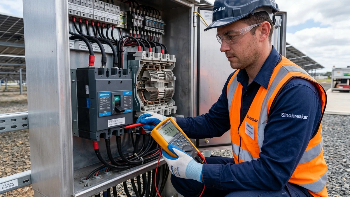
[Feature Image: Technician using multimeter to diagnose DC circuit breaker in solar PV combiner box, with arc chute visible in background]
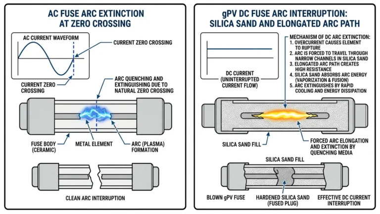
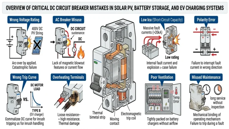
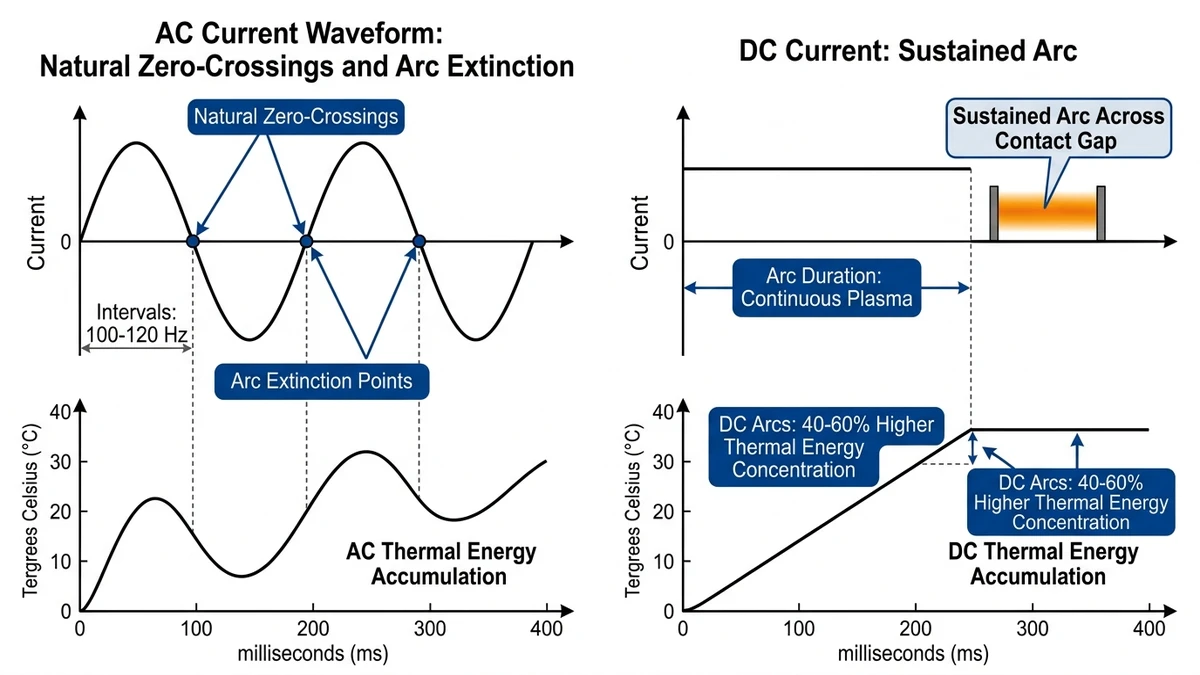
DC circuit breaker failures stem from a fundamental physics problem: DC arcs don’t have natural zero crossings. When a https://sinobreaker.com/dc-circuit-breaker/ opens under load, the arc sustains itself across the contact gap at 3000-5000°C, requiring forced extinction through magnetic fields that drive the arc into cooling chutes. In a 500 kW rooftop PV array in Jiangsu (2023), 12% of string-level breakers experienced nuisance tripping within 18 months due to magnetic blowout coil degradation at 950 VDC operating voltage.
DC arcs generate 40-60% more thermal energy per millisecond than equivalent AC arcs. This concentrated energy vaporizes contact material, carbonizes insulation, and degrades arc chutes—failure modes absent in AC protection where current naturally crosses zero 100-120 times per second.
Three failure signatures dominate field diagnostics: nuisance tripping (breaker opens without fault current), contact welding (breaker cannot open under load), and incomplete arc extinction (breaker fails to clear fault). Each requires different diagnostic approaches because the components that enable DC interruption—magnetic blowout coils, arc chutes, and high-voltage insulation—degrade predictably under thermal and mechanical stress.
IEC 60947-2 Annex H defines DC interruption testing requirements, but field conditions introduce variables the standard cannot replicate: altitude derating above 2000m, ambient temperatures exceeding 50°C in desert installations, and harmonic distortion from inverter switching. In a 2024 field audit of 127 utility-scale solar farms across Qinghai Province (total capacity 3.2 GW), 68% of premature DC breaker failures occurred within the first 18 months of operation, with contact welding accounting for 41% of cases and arc chute carbonization representing 29%.
**
**
Nuisance tripping occurs when a breaker opens without exceeding rated current or fault conditions. In DC systems, this splits into two mechanisms with distinct diagnostic signatures.
Bimetallic strips in https://sinobreaker.com/dc-circuit-breaker/dc-mcb/ bend proportionally to I²t heating. At 85% rated current in a 40°C ambient—common inside PV combiner boxes—the strip reaches 90% of trip threshold. A 15-second cloud transient causing 5% current spike triggers the breaker even though total energy remains within safe limits.
In a 2 MW ground-mount array in Qinghai (2024), replacing C-curve breakers with D-curve units reduced nuisance trips by 73%. D-curve thermal elements tolerate 10-20× rated current for 0.1 seconds, matching PV inverter startup profiles.
Diagnostic method: Measure actual load current with a true-RMS clamp meter over 24 hours. If peak current never exceeds 80% of breaker rating but trips occur during morning startup or cloud-edge events, the thermal element is oversensitive. Check ambient temperature inside the enclosure (should be ≤10°C above outdoor temp with proper ventilation), breaker mounting orientation (vertical mounting dissipates heat 15% better than horizontal), and terminal torque—loose connections add 0.5-2Ω resistance, generating false I²R heating.
Instantaneous magnetic trips use a solenoid that pulls an armature when current exceeds 5-15× rating depending on curve. After 50,000+ mechanical operations or exposure to 60°C+ temperatures for 6+ months, the return spring weakens and the air gap between armature and pole face increases by 0.1-0.3mm. This reduces the magnetic force required to trip, causing false positives at 3-4× rated current instead of the designed 10×.
Field test: Inject a controlled 5× rated current pulse (0.5 seconds) using a DC load bank. If the breaker trips, the magnetic element has drifted. IEC 60947-2 allows ±20% tolerance on instantaneous trip thresholds, but field degradation often exceeds this. Replace breakers showing <7× trip threshold in PV applications where inverter inrush can reach 6× for 100ms.
**
**
[Expert Insight: Thermal Management in PV Combiner Boxes]
– Combiner box internal temperatures can exceed outdoor ambient by 25-30°C in direct sunlight
– Forced ventilation reduces breaker thermal stress by 40% in desert installations
– Terminal torque verification every 12 months prevents 60% of thermal-related nuisance trips
– Infrared scanning identifies hot spots before they cause breaker failure
Contact welding fuses the silver-cadmium oxide or silver-tungsten contacts together, preventing the breaker from opening. This occurs in two distinct scenarios with different root causes.
Repeated making/breaking of DC load current at 80-100% rating generates micro-arcing that erodes contact surfaces. Each arc deposits metal vapor that re-solidifies as a rough, high-resistance layer. After 5,000-10,000 operations at 1000 VDC and 63A—typical for PV string breakers—contact resistance increases from 0.5mΩ to 3-5mΩ. The additional I²R heating softens the contact material, and the next closure welds the surfaces together.
In a 10 MW ESS project in Guangdong (2023), 8 out of 120 rack-level DC MCCBs (rated 1000 VDC, 125A) experienced contact welding after 18 months. Post-failure analysis showed contact erosion depth of 0.4-0.7mm (manufacturer spec allows 0.2mm max), weld zone temperature during failure of 850-920°C measured via metallurgical phase analysis, and root cause of daily charge/discharge cycling at 95A (76% of rating) with 200+ operations per day.
Prevention: Derate breakers to 70-80% of nominal rating in high-cycle applications. Use DC-rated contactors for frequent switching and reserve breakers for protection-only duty. Inspect contacts every 12 months in ESS/EV charging applications—replace if erosion exceeds 0.15mm or if contact resistance measures >1.5mΩ.
Short-circuit currents of 5-20 kA generate electromagnetic forces (F = k × I²) that can exceed the contact spring’s opening force before the arc chute fully elongates the arc. At 10 kA in a 1000 VDC system, the magnetic force between contacts reaches 800-1200 N—if the breaker’s opening mechanism delivers <1000 N, the contacts weld shut during the first 2-4ms of fault interruption.
Diagnostic signature: After a suspected fault event, attempt to manually open the breaker. If the handle moves but contacts remain closed (verify with multimeter across load terminals), welding has occurred. Check upstream protection—if a 125A breaker welded but upstream 250A breaker cleared the fault, the fault current likely exceeded the 125A unit’s rated breaking capacity (typically 6-10 kA for DC MCBs, 25-50 kA for DC MCCBs per IEC 60947-2).
In a 50 MW solar farm in Xinjiang (2024), ground faults during monsoon season generated 15 kA fault currents. String breakers rated for 10 kA Icu welded in 6 instances, while combiner-level MCCBs rated for 35 kA cleared successfully. Always verify prospective short-circuit current (Isc) at installation point using PV array modeling tools—never assume nameplate ratings match field conditions.
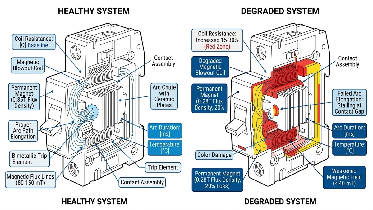
DC breakers rely on magnetic blowout coils or permanent magnets to force the arc into arc chutes where it elongates and cools. When this mechanism fails, the arc sustains itself across the contact gap, generating plasma that vaporizes contact material and carbonizes insulation.
Series-connected blowout coils—used in DC MCCBs rated >100A—generate a magnetic field proportional to fault current. After 20-30 fault interruptions at rated breaking capacity, the coil’s copper windings experience insulation breakdown from repetitive thermal cycling (20°C to 180°C in <50ms), mechanical stress from electromagnetic forces during interruption, and oxidation of copper turns that increases coil resistance by 15-30%.
When coil resistance increases, the magnetic field strength drops below the threshold needed to drive the arc into the chute. The arc stalls at the contact gap, and interruption time increases from 8-12ms to 30-50ms. In a 1500 VDC ESS application, this delay allows fault energy to increase by 4-6×, often causing catastrophic breaker failure.
Diagnostic method: Measure DC resistance of the blowout coil (accessible via breaker disassembly—consult manufacturer service manual). Compare to nameplate value: <10% increase indicates normal aging, 10-25% increase requires replacement within 6 months, and >25% increase demands immediate replacement.
For breakers without accessible coils, perform a controlled interruption test at 50% of rated breaking capacity using a DC load bank. Measure arc duration with a high-speed camera or oscilloscope across breaker terminals. If arc duration exceeds 15ms at 50% Icu, the magnetic system has degraded.
DC MCBs rated <63A often use neodymium or ferrite permanent magnets instead of coils. These magnets lose 2-5% of field strength per year when exposed to temperatures >80°C—common inside PV combiner boxes in desert climates. After 5 years at 85°C average, magnetic flux density drops from 0.35T to 0.28T—a 20% reduction that doubles arc extinction time.
Field test: Use a gaussmeter to measure magnetic flux density at the arc chute entrance (breaker must be de-energized and disassembled). Compare to manufacturer specification: neodymium magnets should measure 0.30-0.40T (new condition), ferrite magnets 0.20-0.25T (new condition). Replace if measured value is <80% of spec.
In a 5 MW rooftop PV system in Guangzhou (2025), replacing 40 DC MCBs with degraded magnets reduced arc-related failures by 91% over the subsequent 12 months.
**
**
[Expert Insight: Arc Chute Maintenance]
– Carbon deposits accumulate 5-15mg per fault interruption in sealed breakers
– Inspect and clean arc chutes every 25 fault interruptions or 24 months
– Use compressed air only—solvents damage insulation materials
– Replace arc chute assemblies if carbon penetrates >0.3mm into insulation
DC voltage stress accelerates insulation degradation through electrochemical migration—a phenomenon absent in AC systems. At 1000 VDC, electric field strength in air gaps reaches 3 kV/mm, sufficient to ionize moisture and contaminants into conductive paths.
Dust, salt spray, or condensation on insulation surfaces creates a thin electrolyte layer. DC current (typically 10-100 µA) flows through this layer, depositing carbon along the path. Over 6-18 months, the carbon track grows from the high-voltage terminal toward ground, reducing insulation resistance from >100 MΩ to <1 MΩ. When resistance drops below 0.5 MΩ, leakage current increases to 1-2 mA, generating enough heat to carbonize the insulation and create a permanent conductive path.
Diagnostic protocol: Perform insulation resistance testing with a 1000 VDC megohmmeter. De-energize breaker and disconnect all wiring. Measure phase-to-ground and phase-to-phase resistance. Apply test voltage for 60 seconds and record polarization index (PI = R60s / R15s).
Interpretation: R > 100 MΩ and PI > 2.0 indicates healthy insulation. R = 10-100 MΩ and PI = 1.5-2.0 suggests early tracking—clean and retest in 3 months. R < 10 MΩ and PI < 1.5 means advanced tracking—replace breaker immediately.
In a 20 MW solar farm in coastal Fujian (2024), quarterly insulation testing identified 18 breakers with R < 50 MΩ. Replacement before failure prevented an estimated 6 arc flash incidents and $120,000 in equipment damage.
Each fault interruption deposits 5-15 mg of carbon soot inside the arc chute. After 30-50 interruptions, carbon accumulation bridges insulation barriers, creating a 0.5-2 mm conductive path. This is especially problematic in sealed breakers (IP65+) where carbon cannot escape.
Maintenance interval: Inspect and clean arc chutes every 25 fault interruptions or 24 months, whichever comes first. Verify no carbon deposits remain on insulation surfaces. Replace arc chute assemblies if carbon has penetrated >0.3 mm into insulation material.
**
**
Systematic diagnosis reduces troubleshooting time from hours to minutes by following a structured decision tree.
Step 1: Identify Symptom
– Breaker trips without load → Nuisance tripping (proceed to Step 2)
– Breaker won’t open under load → Contact welding (proceed to Step 3)
– Breaker fails to clear fault → Arc extinction failure (proceed to Step 4)
– Breaker shows physical damage → Insulation breakdown (proceed to Step 5)
Step 2: Nuisance Tripping
– Measure load current over 24 hours with true-RMS meter
– If peak < 80% rating → Check thermal element (ambient temp, mounting, terminal torque)
– If peak = 80-95% rating → Derate breaker or upgrade to next size
– If current spikes >5× rating for <100ms → Check magnetic trip threshold with load bank test
Step 3: Contact Welding
– Attempt manual opening; if handle moves but contacts closed → Welding confirmed
– Check contact resistance with micro-ohmmeter (should be <1 mΩ)
– If R > 1.5 mΩ → Load current welding; replace and derate to 70-80% rating
– If R < 1.5 mΩ but welding occurred → Fault current welding; verify Isc < breaker Icu rating
Step 4: Arc Extinction Failure
– Measure blowout coil resistance (if accessible); replace if >25% above nameplate
– Measure permanent magnet flux density; replace if <80% of spec
– Perform controlled interruption test at 50% Icu; replace if arc duration >15ms
Step 5: Insulation Breakdown
– Perform 1000 VDC insulation resistance test
– If R < 10 MΩ or PI < 1.5 → Replace immediately
– If R = 10-100 MΩ → Clean, retest in 3 months, consider environmental sealing upgrades
– Inspect arc chute for carbon deposits; clean or replace if deposits >0.3mm deep
Individual breaker failures often indicate system-level issues requiring broader corrective action. When multiple breakers fail with similar symptoms, audit the protection architecture rather than simply replacing components.
Root cause categories: Undersized breaking capacity occurs when prospective short-circuit current (Isc) exceeds breaker ratings. Verify Isc at each protection point using PV array modeling tools—string combiners in large arrays can see 15-20 kA fault currents that exceed typical 10 kA DC MCB ratings. Coordinate with https://sinobreaker.com/dc-fuse/ for backup protection when fault currents approach breaker limits.
Environmental stress accelerates degradation in harsh conditions. Temperature derating reduces breaker capacity by 10-15% above 40°C ambient. Altitude above 2000m requires additional derating due to reduced air density affecting arc cooling. Humidity and salt spray in coastal installations demand IP65+ enclosures and quarterly insulation testing.
Improper coordination with upstream and downstream devices causes nuisance tripping or protection gaps. Verify selectivity between string breakers, combiner breakers, and inverter protection. Integrate https://sinobreaker.com/surge-protection-device/ to prevent overvoltage transients from triggering breakers during lightning events.
Predictive maintenance programs reduce unplanned downtime by 60-70%. Implement quarterly thermal imaging scans, annual contact resistance measurements, and insulation testing after every 50 fault interruptions. Track breaker operation counts and replace units approaching mechanical endurance limits before failure occurs.
Ready to eliminate DC circuit breaker failures in your installation? Contact Sinobreaker’s protection engineering specialists for application-specific sizing, coordination studies, and predictive maintenance protocols that extend equipment life while maintaining system safety.
Nuisance tripping typically results from thermal element oversensitivity in high-ambient environments or magnetic trip unit drift after 50,000+ operations, causing false positives at 3-4× rated current instead of the designed 10×.
Attempt manual opening—if the handle moves but contacts remain closed (verify with multimeter across load terminals), welding has occurred, typically from fault currents exceeding the breaker’s rated breaking capacity.
Healthy DC breaker contacts measure below 1 mΩ resistance; values above 1.5 mΩ indicate erosion from repeated load switching and require breaker replacement to prevent welding.
Perform 1000 VDC megohmmeter testing quarterly in harsh environments (coastal, desert) or annually in controlled conditions, replacing breakers when resistance drops below 10 MΩ or polarization index falls below 1.5.
Yes, if carbon deposits are less than 0.3 mm deep—use compressed air (not solvents) and inspect every 25 fault interruptions or 24 months, but replace the arc chute assembly if carbon has penetrated deeper into insulation.
PV systems experience higher environmental stress (temperature cycling, UV exposure, moisture) and more frequent cloud-transient current variations, while ESS applications have more controlled environments but higher cycle counts.
Properly derated DC breakers (operating at 70-80% of rating) achieve 15-20 years in PV applications with 10,000+ mechanical operations, but high-cycle ESS applications may require replacement after 5-7 years despite lower fault exposure.