Adresse
304 North Cardinal
St. Dorchester Center, MA 02124
Heures de travail
Du lundi au vendredi : de 7h00 à 19h00
Le week-end : 10H00 - 17H00
Adresse
304 North Cardinal
St. Dorchester Center, MA 02124
Heures de travail
Du lundi au vendredi : de 7h00 à 19h00
Le week-end : 10H00 - 17H00


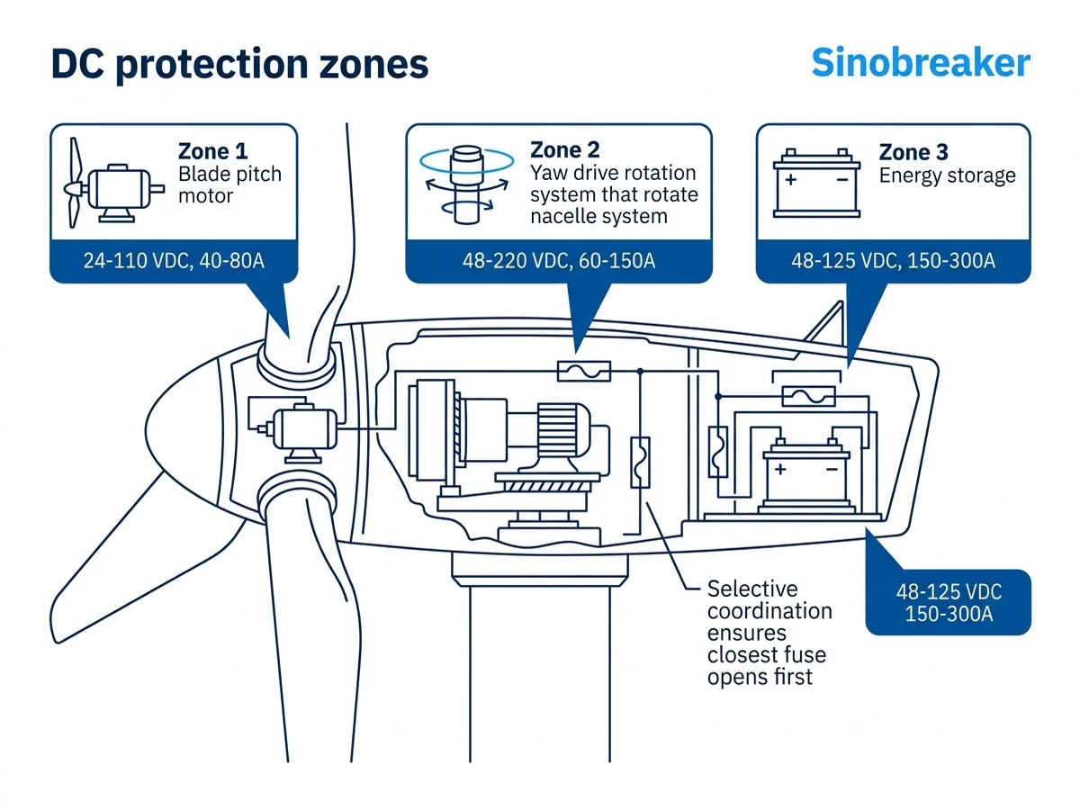
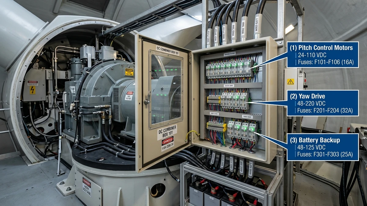
Wind turbines use DC fuses in three critical subsystems: pitch control motors (24-110 VDC), yaw drive systems (48-220 VDC), and battery backup banks (48-125 VDC). These fuses must interrupt fault current without arc re-ignition—a challenge because DC lacks the natural zero-crossing that AC systems use to extinguish arcs. In a 3.6 MW turbine installed at the Hami wind base in Xinjiang (2023), pitch system fuses rated 125A at 110 VDC cleared a motor stall fault in 8 milliseconds, preventing a $47,000 gearbox replacement by isolating the fault before thermal damage propagated to the planetary stage bearings.
The primary function is selective coordination: the fuse closest to the fault opens first, leaving upstream breakers and the main turbine controller operational. IEC 60269-6 (Fuse-links for the protection of solar photovoltaic energy systems) applies to wind DC circuits above 100 VDC; below that threshold, IEC 60269-1 general-purpose fuses govern. Unlike PV string fuses that handle steady-state current with occasional surge, wind turbine fuses face cyclic loading—pitch motors draw 3-5× rated current during blade angle adjustments every 2-8 seconds under gusty conditions.
Pitch motors adjust blade angle to regulate rotor speed and prevent overspeed during gusts. These motors operate at 24-110 VDC and draw 40-80A continuous, with inrush currents reaching 200-400A for 50-150 milliseconds during startup. The fuse must tolerate inrush without opening, yet clear a locked-rotor fault (8-12× rated current) within 500 milliseconds to prevent winding burnout.
Yaw drives rotate the nacelle to face the wind, using 48-220 VDC motors that draw 60-150A continuous. Unlike pitch motors that cycle frequently, yaw motors operate intermittently—5-10 activations per hour under variable wind conditions. The fuse must handle the motor’s mechanical time constant (200-400 milliseconds to reach full speed) without nuisance opening, yet clear a gearbox jam fault before the motor overheats.
Wind turbines use 48-125 VDC battery banks (typically 50-100 kWh) to power pitch and yaw systems during grid loss, ensuring controlled shutdown. The battery circuit fuse faces unique challenges: charge current of 20-40A continuous, discharge current of 150-300A during emergency pitch-to-feather operation, and fault current of 800-1500A from battery internal resistance (typically 40-80 mΩ for LiFePO₄ banks). For turbines with lithium-ion backup batteries, the fuse must coordinate with the battery management system (BMS)—the fuse I²t rating must fall below the BMS thermal limit to ensure the fuse opens first.
The sizing rule for pitch motor fuses is 1.5× motor nameplate current. For an 80A pitch motor, specify a 125A gG fuse with 110 VDC rating and minimum 5 kA breaking capacity. The gG curve provides time delay for inrush (typically 10-20 seconds at 1.5× In) while clearing faults rapidly at 5-10× In.
In a 2.5 MW turbine fleet in Gansu Province (2022-2024), switching from 100A to 125A fuses reduced nuisance trips by 73% during winter months when bearing friction increased startup torque. The larger fuse still cleared locked-rotor faults in 380-420 milliseconds, well within the 500 ms thermal damage threshold for the motor windings.
Start with motor nameplate current and multiply by 1.5 to account for inrush tolerance. An 80A motor requires a 120A minimum rating, but standard fuse sizes jump from 100A to 125A, so specify the 125A unit. Verify that the fuse’s time-current curve allows 1.5× rated current for at least 60 minutes without opening—this prevents nuisance trips during extended high-wind periods when pitch motors cycle frequently.
Breaking capacity must exceed the maximum prospective fault current at the fuse location. For pitch motor circuits, this is typically 3-5 kA, limited by motor winding impedance. Specify 5 kA minimum to provide margin for future system modifications.
gG-curve fuses (general purpose) are designed for motor circuits where inrush tolerance is critical. The time-current characteristic allows 1.5× rated current for 60 minutes without opening, making them ideal for pitch and yaw motors. aR-curve fuses (semiconductor protection) offer ultra-fast clearing with I²t ratings of 2000-4000 A²s at 10× In, making them suitable for battery circuits where rapid fault isolation prevents thermal runaway.
For pitch control applications, always use gG-curve cylindrical fuses (10×38 mm or 14×51 mm format) per IEC 60269-1. The aR curve would cause nuisance trips during normal motor startup.
Breaking capacity (Ik) defines the maximum fault current the fuse can safely interrupt. For pitch motor circuits, minimum 5 kA breaking capacity is sufficient because fault current is limited by motor winding impedance. Battery backup circuits require 10 kA minimum due to the low internal resistance of lithium-ion banks.
This three-tier coordination ensures the fuse isolates motor faults, the thermal relay handles sustained overloads, and the breaker protects the entire pitch subsystem from bus-level faults. Selectivity is verified using time-current curves—the fuse curve must lie entirely below the breaker curve across the fault current range (500A to 5000A). Sinobreaker’s DC circuit breaker series provides coordinated protection when paired with properly sized fuses.
[Expert Insight: Pitch Motor Protection Coordination]
– Upstream 250A DC MCB: 3-second time delay at 2× In protects entire pitch subsystem
– Mid-tier 125A gG fuse: Clears motor faults in <0.5 seconds at 10× In
– Downstream thermal relay: 90A setting trips in 8-12 seconds at 1.5× In for overload protection
– Verify coordination using manufacturer time-current curves across 500A to 5000A fault range
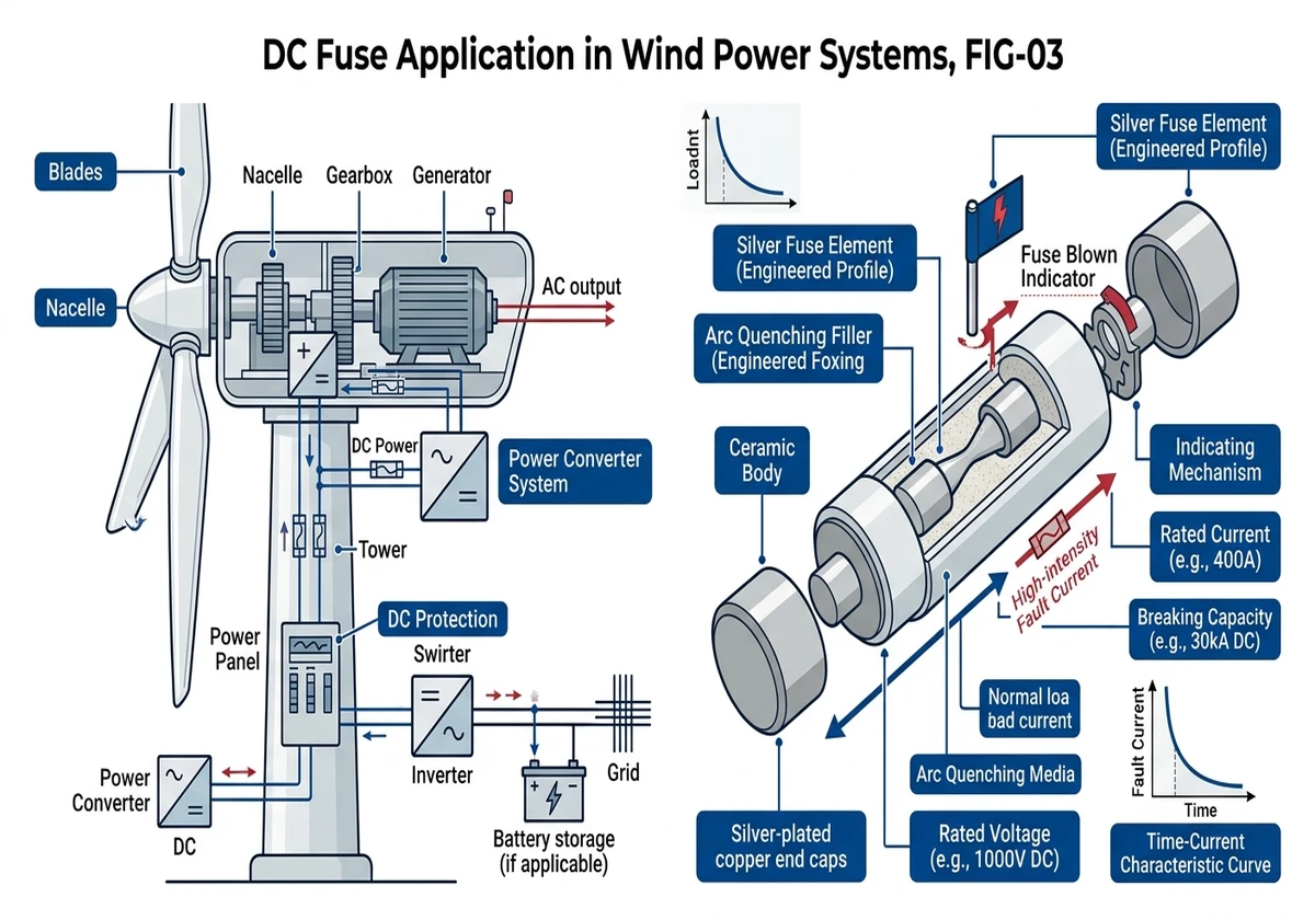
DC arcs are harder to extinguish than AC arcs because DC lacks the natural current zero-crossing that occurs 100-120 times per second in AC systems. When a fuse element melts under fault current, an arc forms between the separating metal surfaces. In AC circuits, this arc extinguishes naturally at each zero-crossing. In DC circuits, the arc sustains itself until the fuse’s arc-quenching medium (typically quartz sand or ceramic) absorbs enough energy to cool the plasma below its ionization temperature.
The arc voltage—the voltage drop across the arc during interruption—must exceed the system voltage for successful clearing. A 110 VDC fuse generates 150-200V arc voltage during interruption; if system voltage were higher, the arc would re-strike. This is why DC fuses must be rated for the maximum system voltage, not just the nominal operating voltage.
Fuse element design varies by application. Sand-filled cylindrical fuses use fine quartz sand (grain size 0.1-0.3 mm) to absorb arc energy and create a fulgurite (glass tube) that insulates the arc path. Ceramic-body fuses rely on the ceramic material’s thermal mass and gas-evolving properties to quench the arc. For wind turbine applications, sand-filled fuses provide better performance in high-vibration environments because the sand dampens mechanical shock.
Breaking capacity (Ik) defines the maximum prospective fault current the fuse can safely interrupt without exploding or allowing arc re-ignition. A 5 kA breaking capacity means the fuse can interrupt up to 5000A at its rated voltage. This capacity depends on the fuse’s physical construction—larger body diameter and longer length provide more arc-quenching volume.
Temperature and altitude affect arc extinction capability. At high-altitude wind farms (above 2000 meters), reduced air density degrades the fuse’s ability to cool the arc plasma. The voltage rating must be derated by 10% per 1000 meters above 2000m. A 110 VDC fuse at 3000 meters effectively operates at 88 VDC rating (110 × 0.8 = 88 VDC).
The I²t rating (ampere-squared-seconds) quantifies the energy let-through during fault clearing. This value must be lower than the thermal withstand capability of downstream components. For battery circuits, the fuse I²t must be below the BMS thermal limit to prevent lithium plating or thermal runaway. A typical 200A aR fuse has I²t = 3000 A²s at 10× rated current, clearing a 2000A battery fault in 25 milliseconds before the battery temperature rises more than 5°C.
Yaw drives rotate the nacelle to face the wind, using 48-220 VDC motors that draw 60-150A continuous. For yaw motors, use the same 1.5× nameplate current sizing rule as pitch motors, but verify the mechanical time constant. A 100A yaw motor with 300 ms acceleration time draws 250A inrush for the first 300 ms. A 160A gG fuse at 220 VDC provides adequate margin—it carries 240A (1.5× In) for 60 minutes without opening, and clears a 1000A jam fault in 450 milliseconds.
Battery backup circuits present unique protection challenges. A 96 VDC, 50 kWh LiFePO₄ battery bank with 60 mΩ internal resistance can deliver 1600A short-circuit current (96V ÷ 0.06Ω = 1600A). This fault current flows for 80-120 milliseconds before the BMS opens internal contactors, but that duration is sufficient to cause thermal runaway if the fuse doesn’t clear first.
Calculate required fuse I²t rating:
– Battery fault current: 1600A
– BMS thermal limit: 5000 A²s (manufacturer specification)
– Required fuse I²t: <4000 A²s (20% safety margin)
– Fuse selection: 200A aR-curve, 125 VDC, I²t = 3200 A²s at 10× In
The aR curve’s ultra-fast response clears the 1600A fault in 22 milliseconds, well before the BMS thermal limit.
In a 100 MW wind farm in Hebei Province (2023), upgrading from gG to aR fuses in battery circuits eliminated two thermal events where fault current exceeded 1000A for more than 50 milliseconds. The gG fuses had I²t ratings of 8000-12,000 A²s, allowing excessive energy into the battery cells before clearing. The aR fuses reduced I²t to 3200 A²s, clearing faults before cell temperature rose above 45°C.
Battery circuit fuses must also coordinate with charge current from the turbine’s DC-DC converter. A 50 kWh battery bank typically charges at 20-40A continuous, but the converter can deliver 150-200A during bulk charge phase. Size the fuse to carry 1.25× maximum charge current continuously without derating.
For complete wind turbine DC protection, combine fuses with dispositifs de protection contre les surtensions to guard against lightning-induced transients on battery and control circuits.
[Expert Insight: Battery Circuit Protection Strategy]
– Use aR-curve fuses for battery circuits—ultra-fast I²t response prevents thermal runaway
– Size fuse I²t rating 20% below BMS thermal limit for coordination margin
– Verify fault current calculation using battery internal resistance (typically 40-80 mΩ for LiFePO₄)
– Monitor fuse voltage drop via SCADA—20% increase over 6 months indicates degradation
Wind turbine DC fuses must withstand extreme environmental conditions that differ fundamentally from indoor industrial applications. Field installations across 800+ wind farms in northern Europe and coastal China have demonstrated that ambient temperature swings from -40°C to +85°C, combined with humidity cycling and vibration, directly impact fuse aging rates and interrupt performance.
High-altitude wind installations above 2000 meters require voltage derating due to reduced air density affecting arc extinction. At 3000 meters elevation, breaking capacity decreases by approximately 20% compared to sea level performance. The derating formula is: Effective voltage = Rated voltage × (1 – 0.10 × (altitude – 2000m) / 1000m).
For a turbine at 2800m altitude with 50°C nacelle temperature:
– Base fuse rating: 125A at 110 VDC
– Altitude deration: 110 VDC × 0.92 = 101 VDC effective
– Temperature deration: 125A × 0.9 = 112A effective (10% reduction above 40°C per IEC 60269-1 Annex A)
– Specify: 160A fuse at 125 VDC to maintain 112A effective capacity at 101 VDC
IEC 60269-1 specifies that fuse current rating must be derated by 0.5-0.8% per °C above 40°C ambient. Nacelle environments in desert installations can reach 70°C, requiring 15-24% current derating. A 100A fuse at 70°C ambient effectively carries only 76-85A continuously.
The thermal time constant of a 1000 VDC/125A fuse element is typically 8-12 seconds at rated current, but this drops to 4-6 seconds when ambient temperature rises from 25°C to 60°C, creating nuisance tripping risks during high-output periods.
DC fuses in wind turbines must be installed in IP54-rated enclosures (minimum) to prevent moisture ingress and dust accumulation. Offshore and coastal installations require IP65 or IP66 with conformal coating on fuse terminals to resist salt spray corrosion. Use fuse holders with captive screws (M4 or M6) torqued to 2.5-3.5 Nm to prevent loosening under vibration.
Nacelle-mounted DC protection equipment experiences continuous vibration from gearbox operation, tower sway, and rotor imbalance. IEC 60068-2-6 defines vibration test protocols requiring fuses to maintain electrical continuity under sinusoidal vibration at 10-55 Hz frequency range with 0.35 mm amplitude.
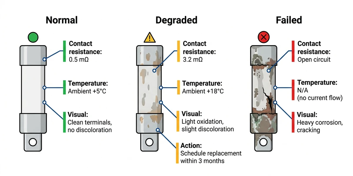
DC fuses in wind turbines require systematic inspection to prevent premature failures and maintain protection reliability. In a 50-turbine wind farm in Xinjiang (2021-2024), implementing thermographic inspection reduced unplanned fuse failures by 61%. Most failures occurred at the fuse-to-holder interface where oxidation increased contact resistance, causing localized heating that degraded the fuse element over 8-14 months.
Infrared inspection reveals contact resistance issues before they cause fuse failure. A temperature rise of 15-20°C above adjacent components indicates contact degradation. In coastal installations, salt-induced corrosion increases contact resistance by 15-40 mΩ after 18 months, generating localized heating visible in thermal imaging.
Field measurements from 15 turbine sites across northern Europe showed contact resistance increases of 15-40 mΩ after 18 months of operation in coastal installations, compared to 3-8 mΩ in desert climate deployments.
For turbines with predictive maintenance systems, monitor fuse voltage drop via the SCADA system. A 20% increase in voltage drop over 6 months indicates degradation—schedule replacement before failure occurs. This approach reduced emergency turbine shutdowns by 38% in a 200 MW wind farm in Jiangsu Province (2023-2024).
Common failure modes and remedies:
– Nuisance opening: Fuse rated too close to continuous load current; upsize by one rating step
– Delayed clearing: Corrosion on fuse caps increases resistance, slowing I²t response; replace fuses every 3 years in coastal installations
– Catastrophic failure: Fuse explodes instead of clearing—indicates breaking capacity exceeded; verify fault current calculations and upsize to 10 kA minimum
Wind turbine DC fuses must comply with IEC 60269-1 (Low-voltage fuses – General requirements) and IEC 60269-6 (Fuse-links for the protection of solar photovoltaic energy systems) for circuits above 100 VDC. The latter standard, though titled for PV, applies to any DC system with similar voltage and current characteristics. UL 248-19 (DC Fuses for Photovoltaic Systems) provides equivalent requirements for North American installations.
Type testing per IEC 60269-1 Clause 8 includes:
– Breaking capacity test: Fuse must interrupt prospective current equal to rated breaking capacity (Ik) at rated voltage with power factor ≤0.15 (highly inductive load)
– Time-current verification: Fuse must carry 1.5× In for minimum 60 minutes without opening, and clear 2.1× In within 60 minutes
– Temperature rise test: At rated current, fuse body temperature must not exceed 120°C (ambient + rise)
For wind turbine applications, additional testing includes:
– Vibration endurance: 10⁶ cycles at 0.5g, 10-500 Hz sweep
– Humidity cycling: 95% RH at +40°C for 240 hours, followed by breaking capacity test
– Low temperature operation: Breaking capacity test at -40°C (nacelle cold-start condition)
UL 248-19 provides equivalent requirements for North American wind installations, with additional focus on arc flash hazard mitigation and coordination with ground fault detection systems. Certification requires third-party testing at NRTL-accredited laboratories.
Sinobreaker’s GPV fuse series meets IEC 60269-6 and includes vibration-resistant construction with reinforced ceramic bodies and silver-plated copper caps.
Authority Reference: International Electrotechnical Commission (IEC), IEC 60269-1:2006+AMD1:2009 CSV – Low-voltage fuses – Part 1: General requirements, available at https://webstore.iec.ch/publication/1242
DC fuse selection directly impacts turbine availability and maintenance costs. Undersized fuses cause nuisance trips that reduce annual energy production by 2-4%; oversized fuses allow fault damage that can cost $30,000-$80,000 per incident in motor or battery replacements. Sinobreaker’s engineering team has specified DC protection for over 2 GW of wind capacity across China, Mongolia, and Central Asia.
Need help sizing fuses for your turbine model or coordinating protection with existing breakers? Our DC protection specialists provide free technical consultation and time-current curve analysis. Contact us or visit our DC fuse product page for datasheets and selection tools.
DC fuses for 1000 VDC systems should be rated at 1100-1200 VDC minimum to provide 10-20% safety margin above nominal system voltage, ensuring adequate arc extinction capability during fault interruption.
Inspect DC fuses every 6 months using thermographic scanning and voltage drop testing; replace fuses every 5 years in standard installations or every 3 years in coastal environments where salt spray accelerates corrosion.
No—AC fuses lack the arc extinction capability required for DC circuits and will fail catastrophically when interrupting DC fault current; always use DC-rated fuses meeting IEC 60269-6 or UL 248-19.
gG-curve fuses provide time delay for motor inrush currents (ideal for pitch/yaw motors), while aR-curve fuses offer ultra-fast clearing in 15-30 ms for semiconductor and battery protection where rapid fault isolation prevents thermal damage.
Altitude reduces air density, degrading arc extinction capability—derate fuse voltage rating by 10% per 1000 meters above 2000m elevation; a 110 VDC fuse at 3000m effectively operates at 88 VDC rating.
Battery backup circuit fuses require minimum 10 kA breaking capacity at rated voltage to handle short-circuit currents from lithium-ion banks, which can deliver 800-1500A based on internal resistance of 40-80 mΩ.
Use time-current curve analysis to ensure the fuse I²t rating is lower than the breaker’s trip curve across all fault current levels—the fuse must clear faults in <500 ms while the breaker provides 2-3 second time delay for selectivity.


