Adresse
304 North Cardinal
St. Dorchester Center, MA 02124
Heures de travail
Du lundi au vendredi : de 7h00 à 19h00
Le week-end : 10H00 - 17H00
Adresse
304 North Cardinal
St. Dorchester Center, MA 02124
Heures de travail
Du lundi au vendredi : de 7h00 à 19h00
Le week-end : 10H00 - 17H00

A DC surge protection device (DC SPD) that has absorbed one too many transients will not always fail visibly, but the warning signs are there if you know what to inspect. According to IEC 61643-11, a degraded SPD can no longer clamp surge voltage to its rated Up protection level, leaving downstream inverters, charge controllers, and PV string equipment exposed.
In a 22 MW ground-mount PV installation in Anhui Province (2023), routine inspection found that 34% of string-level SPDs had triggered their thermal disconnection mechanism silently: no alarms, no tripped breakers, just unprotected circuits running for weeks.
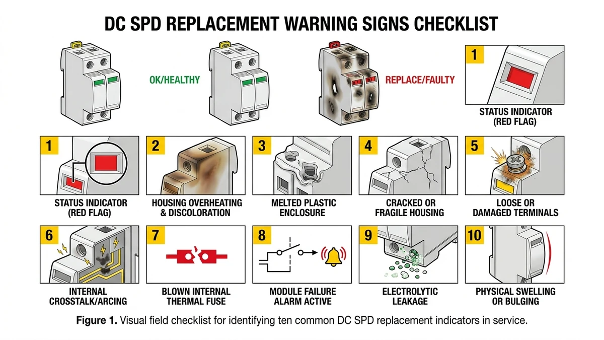
Use this list as a field inspection checklist. Each sign includes a severity tag and the action a technician should take on-site.
To make good replacement decisions in the field, you need to understand what is failing inside the device long before the indicator turns red.
DC SPD failure is usually a MOV (metal oxide varistor) problem. Under repeated surge events, MOV grain boundaries absorb energy and gradually lose clamping precision through a cumulative, irreversible process. IEC 61643-31 governs DC SPDs for photovoltaic applications and sets the test framework for surge withstand, voltage protection level (Up), and end-of-life behavior.
MOVs are zinc oxide ceramic discs that clamp transient overvoltages by shifting from a high-resistance to a low-resistance state in microseconds. Each clamping event deposits thermal energy into the varistor body. Over time, typically after cumulative surge energy exceeds the device’s rated capacity, leakage current at continuous operating voltage (Uc) rises measurably.
Once leakage current climbs above ~1 mA at rated Uc, thermal runaway becomes a real risk: increased leakage → more self-heating → further resistance drop → accelerated degradation. In 1000 VDC string circuits, this cycle can compress what should be years of service life into months under high-lightning-density environments.
A 2023 field review of rooftop PV installations in Guangdong Province covering roughly 35 MW of installed capacity found that SPDs in combiner boxes without remote monitoring showed leakage current drift exceeding 2 mA in 18% of units after two monsoon seasons, well before any visible indicator had triggered.
IEC 61643-31 is the primary standard for low-voltage DC SPDs used in PV systems. It defines:
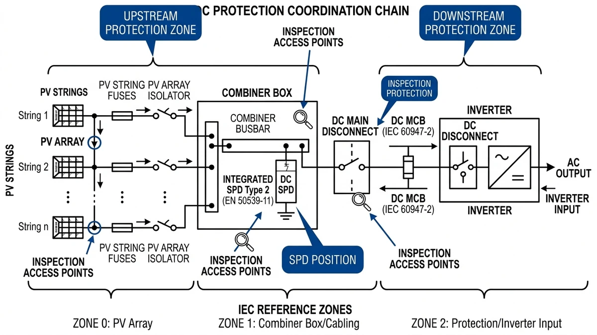
Understanding this degradation path is why pairing a DC SPD with properly rated overcurrent protection matters. A degraded MOV drawing excess leakage current needs a reliable backup disconnect. For broader context on how SPDs fit into PV string protection, proper coordination with upstream Fusibles DC and breakers is critical.
[Expert Insight]
– Leakage-current drift often appears before any mechanical indicator changes, so trend data is more useful than a one-time pass/fail reading.
– If one SPD in a combiner box shows measurable degradation, test the neighboring units in the same exposure zone during the same visit.
– In coastal or humid sites, inspect terminal seals and enclosure gaskets along with electrical values; moisture ingress can accelerate MOV aging.
Testing a DC SPD does not require a full lab setup. A digital multimeter, safe isolation procedure, and a clear pass/fail threshold are enough to catch many failures before they damage other equipment.
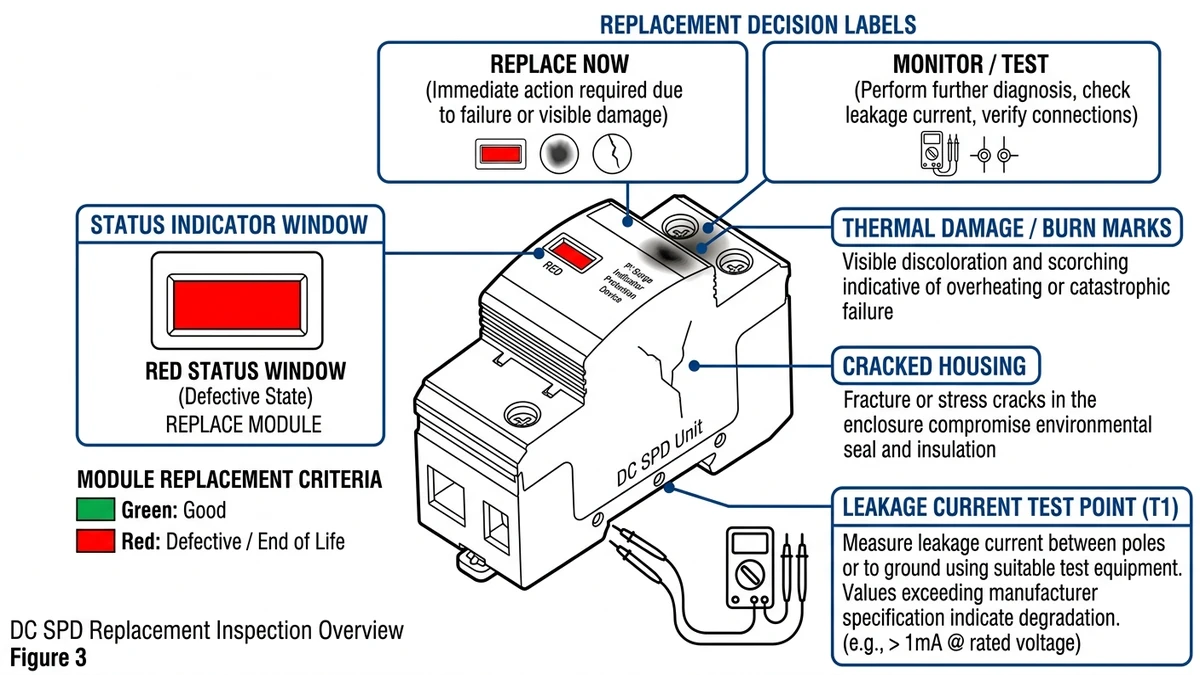
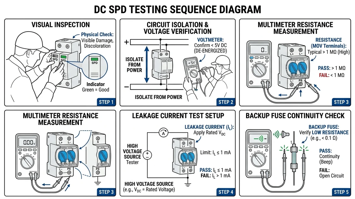
Inspect the SPD housing for burn marks, cracked enclosures, or a tripped status indicator window showing red. A triggered remote signaling contact is a hard stop: do not proceed to electrical testing without isolating the circuit first.
De-energize the string or combiner circuit. Verify zero voltage across the SPD terminals using your meter set to DC voltage. In a 1000 VDC string system, residual voltage above 5 V after isolation suggests a leakage path worth investigating before contact.
Set your multimeter to the highest resistance range, typically 20 MΩ. A healthy MOV usually reads above 1 MΩ between line and ground terminals. Readings below 100 kΩ indicate degradation, meaning the varistor is conducting at rest and may no longer clamp correctly during a surge event. For context on clamping behavior, see this engineering breakdown of 600V DC SPD clamping behavior.
Using a DC insulation tester at 500 V test voltage, leakage current through a serviceable SPD should remain below 1 mA. Values exceeding 5 mA at 500 V DC indicate the MOV is thermally degraded and the Up (protection level) can no longer be guaranteed within the rated ±10% tolerance.
Confirm the series-connected backup fuse or Disjoncteur DC is intact. An open backup fuse with an apparently healthy MOV reading is a common false negative: the SPD looks fine but has no fault-clearing path. In a 60 MW ground-mount installation in Hebei Province (2023), maintenance crews found that roughly 15% of flagged SPD failures were actually blown backup fuses, not MOV degradation.
If an SPD fails inspection and stays in service anyway, the issue shifts from routine maintenance to preventable equipment risk.
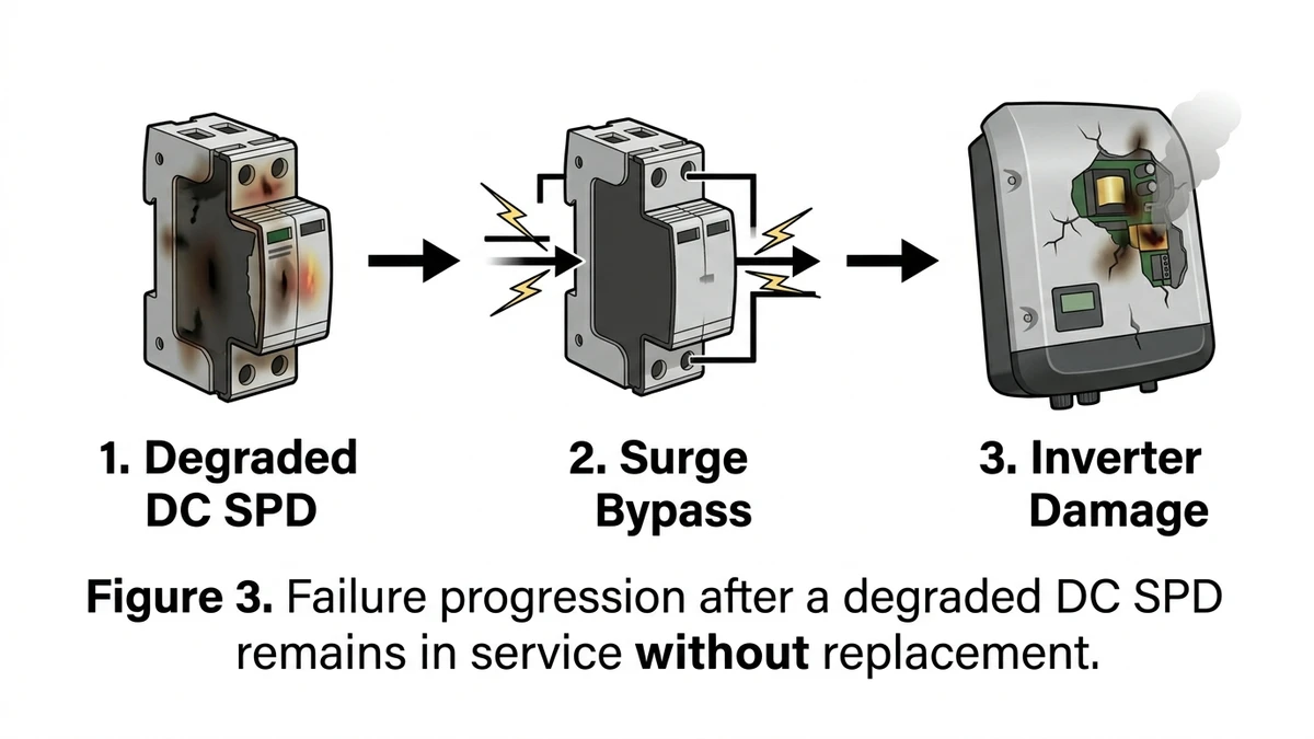
A failed DC SPD does not simply stop protecting; it can leave the circuit effectively open to the next surge event.
When the MOV inside the SPD degrades past its service limit, its clamping voltage rises sharply, often from a rated Up near 2.0 kV to values above 4.0 kV, or the MOV shorts internally and the thermal disconnect isolates it from the circuit. In either case, the next lightning-induced or switching transient passes through without proper attenuation. Once the MOV is bypassed, the SPD’s protection guarantee is gone.
With no functional SPD in the string, every connected component, including inverters, charge controllers, DC distribution boxes, and monitoring hardware, is exposed to full transient energy. Inverter IGBT modules are especially vulnerable; a single unclipped surge above 1500 V in a 1000 VDC string circuit can damage gate oxide layers and create latent failures that appear later under normal load cycling. In a 35 MW ground-mount installation in Hebei Province (2023), post-storm inspection found that three inverters failed within 10 days of a lightning event, and forensic analysis traced the damage to an SPD whose indicator had shown fault for more than two months.
The operational and financial impact compounds quickly. A single failed surge protection device left unreplaced can trigger a cascade: inverter failure leads to string downtime, which may stress adjacent fuse links through unbalanced loading and, in worst cases, contribute to DC arc-fault conditions requiring full boîte de raccordement replacement. Repair costs often run 15–40 times the cost of the SPD itself.
The cost comparison is clear: an SPD replacement often costs less than $50 in string applications, while inverter replacement can run from $2,000 to $8,000. Skipping the inspection is not savings; it is deferred loss.
[Expert Insight]
– After any nearby lightning event, compare current SPD readings against the last maintenance record rather than relying only on the status window.
– When one inverter fails after a surge, inspect the associated combiner-box SPD and backup fuse before energizing a replacement inverter.
– If replacement parts are delayed, isolate the affected string or circuit instead of operating knowingly without surge protection.
When a DC SPD shows warning signs, the main decision is whether to shut down immediately, monitor for a short interval, or involve a specialist.
| Observed Condition | Recommended Action | Urgency |
|---|---|---|
| Status indicator red / window tripped | Replace immediately | Critical — same day |
| Up clamping voltage measured >20% above rated Up | Replace immediately | Critical — within 24 hrs |
| Leakage current >1 mA at operating voltage | Replace immediately | Critical — isolate now |
| Visible burn marks, melted housing, or odor | Replace + inspect upstream protection | Critical — do not re-energize |
| Status indicator yellow / degraded mode | Monitor daily, schedule replacement within 2 weeks | Haut |
| Thermal imaging shows >10°C rise above ambient at SPD terminals | Monitor + retest within 72 hours | Haut |
| No visible fault but SPD age exceeds 10 years in high-surge zone | Schedule replacement at next maintenance window | Medium |
| Single surge event logged, all parameters within spec | Log and continue monitoring | Faible |
In a 22 MW ground-mount installation in Gansu Province (2023), maintenance crews using this triage approach caught three degraded SPDs during routine thermal scans, all showing terminal temperatures 14–18°C above ambient, before any status indicator had tripped.
Before ordering a replacement, verify the new unit matches these parameters against your original design documentation:
When your DC SPD shows clear signs of failure, selecting the right replacement is as important as replacing it promptly. A mismatched device may fail early, underperform, or fail silently during the next surge event.
Start with two non-negotiable electrical ratings. First, the maximum continuous operating voltage (Uc) must meet or exceed the system’s open-circuit voltage. For 1500 V string architectures, that means a Uc of at least 1500 VDC. Second, the nominal discharge current (In) and maximum discharge capability should suit site exposure and system size.
The voltage protection level (Up) determines how much clamping voltage reaches your inverter and combiner box. For 1000 V systems, Up should stay below 4 kV; for 1500 V systems, below 6 kV is a common benchmark. A 20 MWh ESS project in Zhejiang (2024) had three inverters damaged after replacement SPDs were installed with Up values 40% above the inverter’s withstand rating, a preventable mismatch.
For most rooftop and ground-mount PV systems, a Type II SPD handles indirect lightning and switching surges adequately. If the installation is within 50 meters of a direct lightning protection system, a combined Type I+II device is typically the better choice under IEC 62305 installation guidance.
For a complete DC protection stack, pair your replacement SPD with properly rated overcurrent protection. See gPV fuse series if the application requires PV-specific fuse coordination. If you are sourcing a full replacement assembly, Boîtes de raccordement PV with integrated SPD slots can simplify retrofits.
To support maintenance work beyond a single replacement, these references help connect SPD troubleshooting to the rest of the DC protection chain.
For a full technical overview of DC SPD operating principles, clamping-voltage behavior, and selection criteria, the DC surge protection device fundamentals guide covers varistor degradation mechanisms and Up protection levels in detail.
SPD replacement rarely happens in isolation. A degraded SPD often points to upstream or downstream protection gaps, so these resources support a complete protection audit:
In a 22 MW ground-mount installation in Hebei Province (2023), a routine SPD audit triggered by visible window-indicator changes led to the discovery of three additional units with degraded clamping performance, none of which had tripped their thermal disconnect. Cross-referencing SPD condition against the 600V DC SPD clamping voltage engineering guide helped the maintenance team establish a voltage-drift threshold of ±10% as their replacement trigger rather than relying on visual indicators alone.
A red or blank status window, low insulation resistance, rising leakage current, or burn marks are common signs the unit is no longer serviceable. If test values fall outside the rated range, replacement is the safer option.
Yes. Leakage-current drift and clamping-voltage changes can develop before the mechanical indicator trips, which is why electrical testing matters.
A healthy unit will generally read above 1 MΩ between the relevant terminals during an isolation test. A much lower reading suggests the MOV is no longer stable.
You should at least test it for continuity and rating compliance. A new SPD installed with a damaged or mismatched backup device may not clear faults correctly.
Annual inspection is a common baseline, but sites in high-lightning or high-humidity regions often need more frequent checks. Any major surge event should trigger an additional inspection.
If Uc, Up, or discharge ratings do not match the system, the new device may either nuisance-fail or allow excessive surge voltage through to equipment. That can lead to inverter or combiner-box damage during the next transient.
Often yes, because ESS DC architectures, voltage ranges, and equipment withstand levels may differ from standard PV strings. Always match the SPD to the actual DC bus characteristics and installation environment.


