Adresse
304 North Cardinal
St. Dorchester Center, MA 02124
Heures de travail
Du lundi au vendredi : de 7h00 à 19h00
Le week-end : 10H00 - 17H00
Adresse
304 North Cardinal
St. Dorchester Center, MA 02124
Heures de travail
Du lundi au vendredi : de 7h00 à 19h00
Le week-end : 10H00 - 17H00

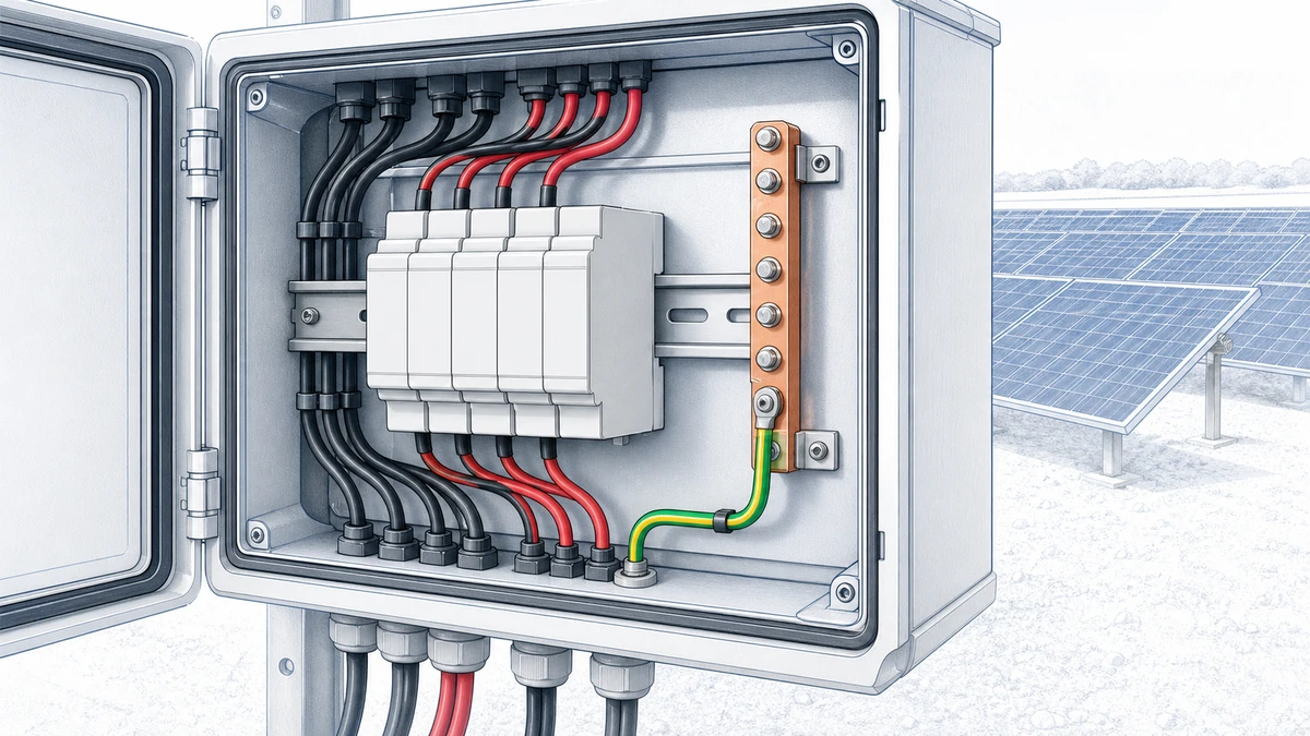
In a photovoltaic DC system, a surge protective device is not defined only by its datasheet rating. Its installed performance depends heavily on wiring layout, especially the **dc spd grounding lead length** between the SPD, the DC conductors, and the grounding or equipotential bonding point.
For Sinobreaker DC SPD applications, this detail matters because PV arrays, combiner boxes, inverters, and DC distribution cabinets often involve long cable routes, high system voltages, and exposed outdoor wiring. A correctly selected SPD can still deliver weaker protection if the connecting conductors are routed poorly or made unnecessarily long.
IEC 61643-32 covers selection, installation, and coordination principles for SPDs used in photovoltaic systems up to 1,500 V DC, including the DC cabling and protective devices between the PV array and the connection point. In practice, that means SPD protection must be evaluated as an installed system, not as a standalone component.
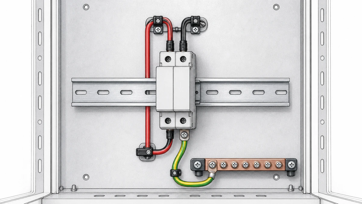
A DC SPD diverts surge current away from protected equipment by providing a controlled discharge path to earth or the bonding network. During a surge event, current rises extremely quickly. Even a short length of conductor has inductance, and that inductance creates a voltage drop when surge current flows.
The protected equipment does not experience only the SPD’s nominal voltage protection level. It experiences the SPD’s clamping behavior plus the voltage added by the connecting conductors.
An SPD datasheet may show a voltage protection level, often based on standardized test conditions. However, field installation adds conductor length on the line side and grounding side. These conductors contribute additional voltage during surge discharge.
Phoenix Contact explains that excessive SPD connecting-cable length increases the effective voltage protection level in the switching equipment. In its illustrated 10 kA impulse example, approximately 1 kV of voltage drop is attributed to one metre of straight conductor. This demonstrates why layout must be considered together with the device rating.
For DC SPD installations, the lesson is direct: shorter, straighter, and better-bonded conductors improve protective performance.
When the grounding lead is too long, the SPD may still conduct surge current, but the protected inverter, monitoring unit, or DC cabinet can be exposed to a higher residual voltage. This can stress insulation, DC input electronics, communication ports, and internal power conversion components.
In PV systems, the issue is more serious because surges may be coupled into long outdoor DC strings. The physical distance between the PV array, combiner box, inverter, and grounding network becomes part of the surge protection design.
The term **dc spd grounding lead length** usually refers to the conductor path from the SPD’s PE, earth, or grounding terminal to the grounding bar, bonding bar, or equipotential connection point. However, installers should also consider the total SPD connection loop.
The grounding lead is important, but the surge current path often includes more than one conductor. Depending on the SPD configuration, the effective connection length can include:
A neat-looking installation can still perform poorly if the surge path is long or routed around the cabinet instead of directly to the bonding point.
The best layout is not always the most visually symmetrical layout. The goal is to minimize impedance in the surge discharge path. That usually means placing the DC SPD close to the protected equipment terminals and close to the grounding or bonding bar.
For Sinobreaker DC SPD installations, the SPD should be positioned so that its line-side and grounding-side leads are as short and direct as the cabinet design allows.
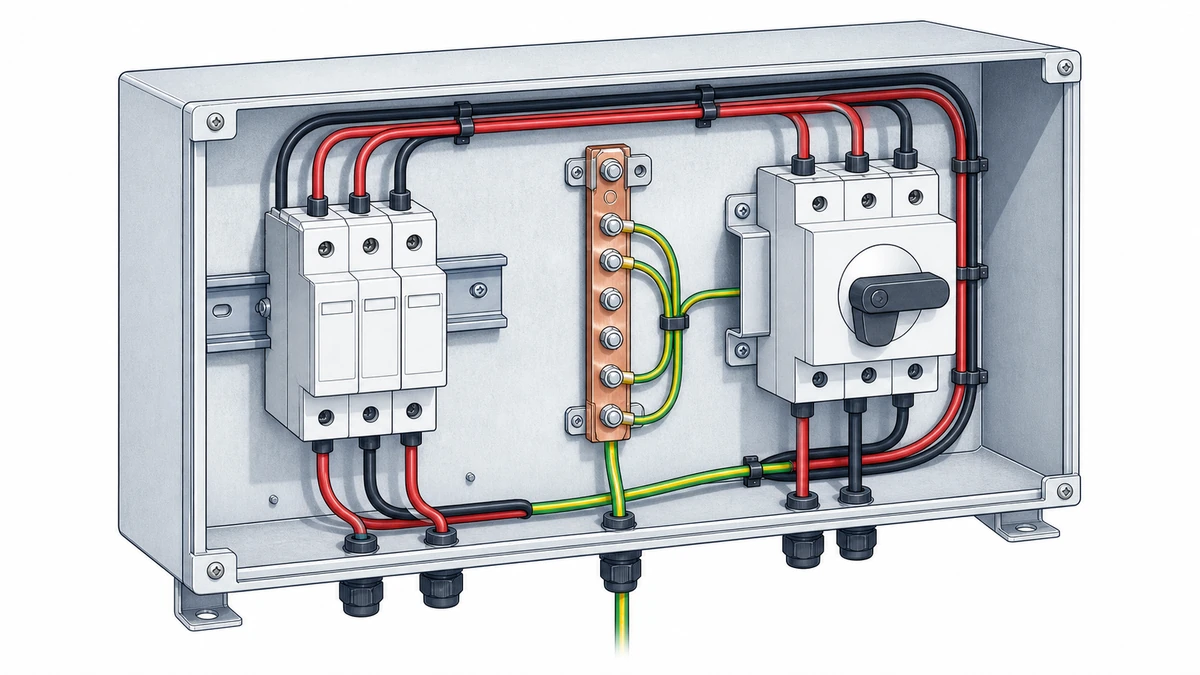
A DC SPD should be installed where it can intercept surge energy before it reaches sensitive equipment. This requires both correct electrical selection and good physical positioning.
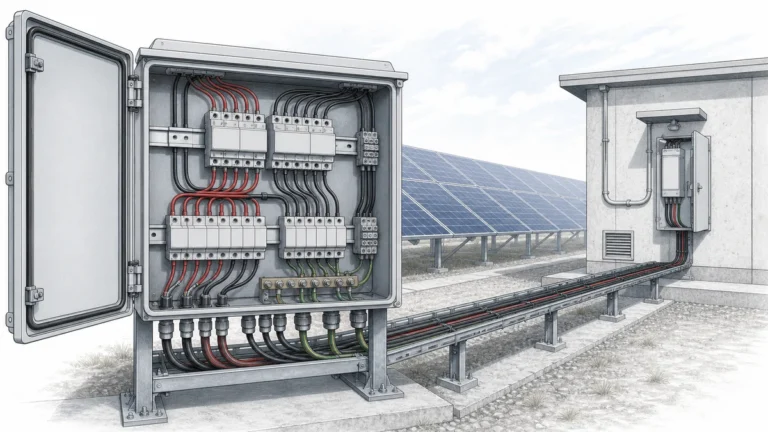
If the inverter DC input is the protected point, the SPD should be installed close to the inverter DC terminals or inside the associated DC distribution cabinet. If the combiner box is the protected point, the SPD should be installed close to the combiner output or string input protection area.
The longer the distance between the SPD and protected equipment, the more cable inductance remains between them. During a surge, that cable can develop a voltage difference that reduces the practical benefit of the SPD.
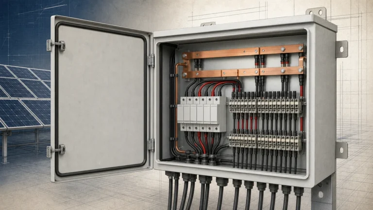
The SPD grounding conductor should connect directly to the cabinet PE bar or equipotential bonding bar. Avoid routing the grounding lead through long cable ducts, across the panel, or around other devices before reaching the bonding point.
Good practice includes:
An SPD cannot work effectively if its discharge path is remote, loose, corroded, or poorly bonded. The grounding system is part of the protection path. For outdoor PV installations, bonding integrity should be treated as a maintenance item, not only an installation detail.
PV systems can include long DC cable runs between modules, combiner boxes, inverter inputs, and DC cabinets. These cable routes influence where SPDs are needed and how they should be coordinated.
Phoenix Contact’s PV guidance states that an additional protective device may be needed at the other end when the cable between PV panels and inverter exceeds 10 m. This illustrates that SPD placement is not only about the device location inside one box. It is also about the distance between exposed cable sections and protected equipment.
When the cable between the PV array and inverter is long, a surge can be induced along the route. If an SPD is installed only at one end, the equipment at the opposite end may remain exposed to excessive transient voltage.
Typical locations to evaluate include:
The final arrangement should follow the project’s risk assessment, applicable standards, local electrical code, and manufacturer instructions.
IEC 61643-32 addresses SPDs in PV systems up to 1,500 V DC and includes principles for selection, installation, and coordination. Coordination means the SPDs, cable lengths, protective devices, and equipment withstand levels should work together.
A high-quality DC SPD cannot compensate for every layout problem. If cable routes are long, bonding is poor, or the SPD is installed too far from the protected device, the effective protection level may rise beyond what sensitive equipment can tolerate.
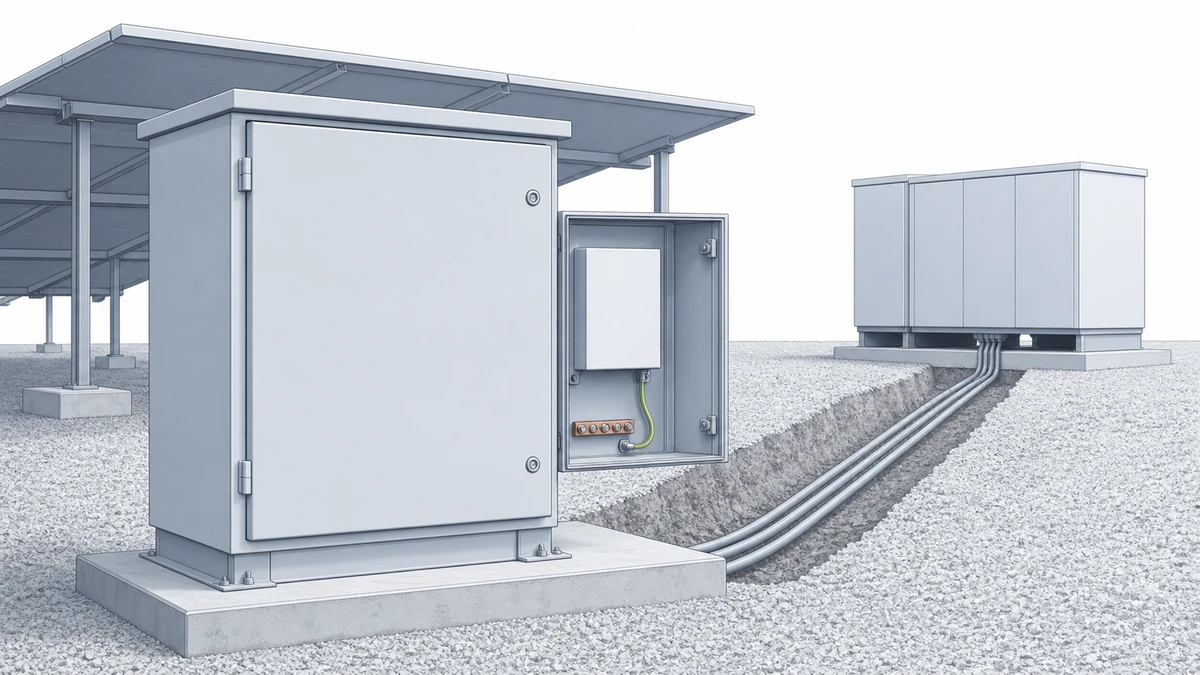
Before finalizing a DC SPD cabinet layout, designers and installers should review the physical surge path. This is especially important for PV combiner boxes, inverter input cabinets, and 1,000 V DC or 1,500 V DC systems.
Review the actual conductor route, not only the schematic. A drawing may show the SPD connected correctly, while the real cabinet layout creates long cable loops.
Key checks include:
For OEM cabinet builders and EPC project teams, SPD placement should be decided during layout design, not corrected after wiring. Moving the SPD closer to the PE bar or DC terminals during the design stage is usually easier than correcting long leads in the field.
In Sinobreaker DC SPD applications, compact mounting near the protected circuit can help reduce the installed residual voltage and improve overall system robustness.
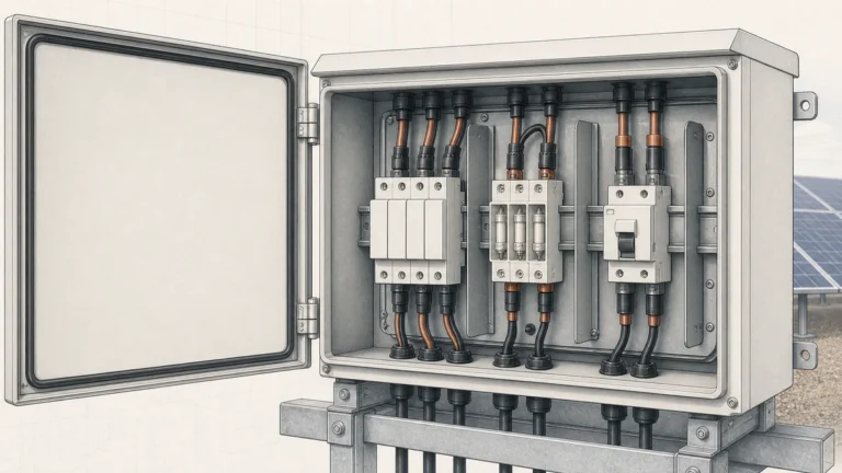
Installers sometimes place SPDs in a convenient location for inspection or replacement. Accessibility is important, especially when using pluggable SPD modules with visual status indicators. However, convenience should not create excessive grounding lead length.
A balanced design keeps the SPD visible and serviceable while maintaining short, direct connections.
Even when the correct DC SPD type and voltage rating are selected, installation problems can reduce performance.
The most common issue is a grounding lead that travels across the enclosure before reaching the PE bar. This increases inductive voltage drop during surge discharge and raises the effective protection level seen by the equipment.
A better solution is to reposition the SPD or PE bar so the grounding path is shorter.
Large loops increase inductance and can couple surge energy into nearby conductors. SPD wiring should be compact, with line and grounding conductors routed close to each other where practical.
Avoid routing the SPD grounding conductor in a completely different path from the DC conductors.
If the enclosure, DIN rail, PE bar, cable gland plate, and grounding system are not properly bonded, surge current may find unintended paths. This can create dangerous potential differences inside the cabinet.
Bonding should be secure, corrosion-resistant, and compliant with applicable installation rules.
For PV systems, the inverter is often one of the most valuable and sensitive devices on the DC side. If the SPD is far from the inverter DC input, the cable between them can still experience high transient voltage.
Where cable length and exposure justify it, protection at both the array side and inverter side should be evaluated.
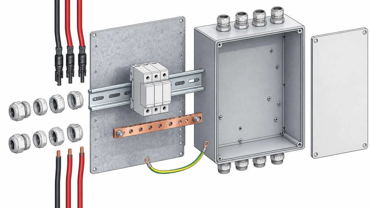
IEC 60364-7-712:2025 addresses selection and application of equipment in PV electrical installations from modules to the connection point. This reinforces an important point: DC SPD installation is part of the complete PV electrical design.
A compliant DC SPD layout should consider:
For PV systems up to 1,500 V DC, IEC 61643-32 provides important SPD selection and coordination principles, while IEC 60364-7-712 addresses broader PV installation requirements. Local regulations and project specifications may add further requirements.
A DC SPD with a suitable nominal discharge current, maximum continuous operating voltage, and voltage protection level is only one part of the solution. The installed conductor arrangement determines how much of that protection is actually delivered to the equipment.
For this reason, **dc spd grounding lead length** should be reviewed during design, installation, inspection, and maintenance.
It matters because surge current creates voltage drop across the SPD connecting conductors. A longer grounding lead can increase the effective voltage protection level seen by the inverter, combiner box, or DC cabinet, even if the SPD itself is correctly rated.
Not always. A higher-rated SPD may handle more surge current or have a suitable voltage rating, but long leads still add inductive voltage drop. The better approach is to select the correct SPD and install it with short, direct, low-impedance connections.
The DC SPD should be installed as close as practical to the inverter DC input or the protected DC cabinet terminals. If the PV cable route is long, protection at both the array side and inverter side may need to be evaluated according to the installation design, IEC guidance, local rules, and manufacturer instructions.