Adresse
304 North Cardinal
St. Dorchester Center, MA 02124
Heures de travail
Du lundi au vendredi : de 7h00 à 19h00
Le week-end : 10H00 - 17H00
Adresse
304 North Cardinal
St. Dorchester Center, MA 02124
Heures de travail
Du lundi au vendredi : de 7h00 à 19h00
Le week-end : 10H00 - 17H00


Lors de la conception des systèmes photovoltaïques (PV), le choix du bon dispositif de protection contre les surintensités peut faire la différence entre un fonctionnement fiable et une défaillance catastrophique. Le fusible gPV, spécialement conçu pour les applications photovoltaïques à courant continu, représente un élément de sécurité essentiel que de nombreux électriciens et installateurs solaires ne comprennent pas entièrement. Contrairement aux fusibles standard à courant alternatif que l'on trouve dans les systèmes électriques résidentiels et commerciaux, les fusibles gPV sont conçus pour répondre aux défis uniques de l'interruption de l'arc électrique en courant continu dans les réseaux solaires à haute tension.
La désignation “g” dans gPV signifie “usage général”, tandis que “PV” indique une application photovoltaïque. Cette catégorie de fusibles spécialisés est née de la reconnaissance du fait que les fusibles conventionnels ne peuvent tout simplement pas interrompre en toute sécurité les courants de défaut continus dans les installations solaires modernes. Lorsqu'un arc CC se forme, il n'y a pas de passage à zéro naturel du courant comme dans les systèmes CA, ce qui rend l'extinction de l'arc beaucoup plus difficile. Sans une technologie d'extinction d'arc appropriée, une condition de défaut peut maintenir l'arc, entraînant des risques d'incendie, des dommages à l'équipement ou une panne complète du système.
Deux normes de certification principales régissent la fabrication et les essais des fusibles gPV : IEC 60269-6 (Commission électrotechnique internationale) et UL 2579 (Underwriters Laboratories). Bien que les deux normes traitent de la protection contre les surintensités photovoltaïques en courant continu, elles diffèrent considérablement en ce qui concerne les procédures d'essai, les tensions nominales, les exigences en matière de pouvoir de coupure et les facteurs de déclassement en fonction de la température. La compréhension de ces différences est essentielle pour les ingénieurs qui spécifient des composants pour des projets internationaux, pour les entrepreneurs qui installent des systèmes dans diverses juridictions et pour les inspecteurs qui s'assurent de la conformité au code.
Les exigences techniques des fusibles gPV vont bien au-delà des simples valeurs nominales de courant. Ces dispositifs doivent démontrer des performances fiables dans des plages de températures extrêmes (de -40°C à +85°C ambiant), supporter une tension continue sans dégradation, interrompre des courants de défaut jusqu'à 30kA ou plus, et maintenir l'isolation électrique après le fonctionnement. En outre, pour sélectionner correctement un fusible gPV, il faut comprendre les valeurs I²t, les caractéristiques temps-courant, la coordination avec les dispositifs de protection en amont et les exigences de dimensionnement de l'article 690.9 du Code national de l'électricité (NEC). Ce guide complet examine la construction technique, les normes de certification, les critères de sélection et l'application correcte des fusibles gPV dans les systèmes solaires photovoltaïques modernes.
La norme CEI 60269-6 de la Commission électrotechnique internationale, intitulée “Fusibles basse tension - Partie 6 : Exigences supplémentaires pour les éléments de remplacement destinés à la protection des systèmes d'énergie solaire photovoltaïque”, établit des critères complets d'essai et de performance pour les fusibles photovoltaïques utilisés dans le monde entier. Publiée pour la première fois en 2010 et révisée par la suite, cette norme traite spécifiquement de l'environnement opérationnel unique des installations photovoltaïques.
Les fusibles gPV certifiés CEI 60269-6 doivent être soumis à des protocoles d'essai rigoureux qui simulent les conditions réelles des systèmes photovoltaïques. La norme impose des essais de vérification à différents niveaux de tension continue, notamment 600V DC, 1000V DC et 1500V DC - des tensions nominales qui correspondent aux architectures des systèmes photovoltaïques modernes. Les essais de pouvoir de coupure selon la norme IEC 60269-6 exigent généralement la démonstration d'une interruption sûre à des courants de court-circuit prospectifs allant de 10 kA à 30 kA, en fonction de la classe de pouvoir de coupure nominale du fusible.
L'une des caractéristiques de la norme CEI 60269-6 est qu'elle exige des essais constants dans le temps. Les réseaux photovoltaïques présentent des caractéristiques d'impédance de source différentes de celles des connexions au réseau électrique ou des systèmes de batteries. La norme exige des essais avec des constantes de temps (rapport L/R) qui reflètent le comportement réel des panneaux photovoltaïques, généralement entre 5 ms et 15 ms. Cela garantit que le fusible peut interrompre avec succès les courants de défaut avec la forme d'onde spécifique et le contenu énergétique présents dans les installations solaires.
Les exigences en matière de cycles de température prévues par la norme IEC 60269-6 sont particulièrement strictes. Les fusibles doivent démontrer des performances stables à des températures de fonctionnement allant de -40°C à +85°C ambiants, avec des essais supplémentaires à des températures élevées allant jusqu'à +140°C pour vérifier la stabilité thermique dans des conditions de défaillance. La norme prévoit également des essais d'humidité, de vibration et d'exposition aux UV, qui sont essentiels pour les fusibles installés dans les boîtes de raccordement extérieures et les boîtes de jonction sur les toits.
UL 2579, “Standard for Fuses for Use in Photovoltaic Systems”, représente l'approche nord-américaine de la certification des fusibles photovoltaïques. Publiée par Underwriters Laboratories et reconnue par le National Electrical Code, la norme UL 2579 établit des exigences spécifiquement adaptées aux installations régies par l'article 690 du NEC.
La norme UL 2579 met l'accent sur la compatibilité avec les exigences d'installation du NEC et se concentre fortement sur la sécurité pratique de l'installation. Les fusibles gPV listés par UL doivent démontrer leur performance aux valeurs nominales de tension et de courant indiquées sur le dispositif, avec des tests effectués avec des facteurs de puissance et des constantes de temps représentatifs des réseaux photovoltaïques. Contrairement aux normes IEC qui utilisent des circuits de test standardisés, les tests UL 2579 intègrent souvent des configurations réelles de modules PV pour vérifier les performances dans le monde réel.
Les exigences de pouvoir de coupure de la norme UL 2579 spécifient généralement un test à un courant de défaut disponible de 10 kA, 15 kA, 20 kA ou 30 kA, la valeur testée étant clairement indiquée sur le fusible. Cette exigence de marquage garantit que les électriciens peuvent vérifier le pouvoir de coupure du fusible par rapport au courant de défaut disponible calculé sur le lieu d'installation - une étape essentielle de la conformité à la norme NEC 110.9.
La norme UL 2579 introduit des exigences spécifiques en matière de compatibilité des porte-fusibles. La norme exige que les fusibles soient testés en combinaison avec les porte-fusibles prévus, afin de s'assurer que l'ensemble complet peut interrompre en toute sécurité les courants de défaut sans éjecter de composants, sans subir d'arc électrique externe ou sans permettre la propagation de la flamme. Cette approche au niveau du système diffère de certaines normes internationales qui testent les éléments de fusibles séparément du matériel de montage.
Les exigences de déclassement de température de la norme UL 2579 s'alignent sur les pratiques d'installation du NEC. Les fusibles doivent inclure des courbes de déclassement publiées montrant comment la température ambiante affecte la capacité de transport du courant. Étant donné que les combinateurs de toit subissent couramment des températures ambiantes supérieures à 60°C en plein soleil, ces facteurs de déclassement ont un impact critique sur les calculs de dimensionnement des fusibles.
| Spécifications | IEC 60269-6 | UL 2579 |
|---|---|---|
| Compétence principale | International/Européen | Amérique du Nord |
| Tension nominale | 600V, 1000V, 1500V DC | 300V, 600V, 1000V, 1500V DC |
| Classes de capacité de rupture | 10kA, 20kA, 30kA | 10kA, 15kA, 20kA, 30kA |
| Test de la constante de temps | 5ms à 15ms (spécifique au PV) | 5ms à 12ms (spécifique au PV) |
| Plage de température | Température ambiante de -40°C à +85°C | Température ambiante de -40°C à +85°C |
| Test des porte-fusibles | Normes distinctes (IEC 60269-3) | Intégré (au niveau du système) |
Les deux normes reconnaissent que l'interruption d'arc en courant continu présente des défis fondamentalement différents de ceux de la protection en courant alternatif. Cependant, leurs approches des tests de vérification reflètent des philosophies réglementaires différentes. La norme CEI 60269-6 établit des paramètres de performance et laisse aux fabricants une certaine flexibilité pour répondre à ces exigences, tandis que la norme UL 2579 spécifie des procédures de test détaillées et des méthodes de vérification au niveau du système alignées sur les pratiques de mise en œuvre du NEC.
💡 Aperçu clé : Bien que les fusibles gPV certifiés IEC et UL offrent une protection DC fiable, vérifiez quelle certification s'applique à votre juridiction avant d'établir les spécifications. Les projets nord-américains devraient donner la priorité aux produits homologués UL 2579 pour faciliter les inspections et la conformité au code.
Le pouvoir de coupure (également appelé pouvoir d'interruption ou pouvoir de coupure en court-circuit) représente le courant de défaut maximal qu'un fusible gPV peut interrompre en toute sécurité sans se rompre, sans maintenir d'arc ou sans créer de risque pour la sécurité. Ce pouvoir, exprimé en kiloampères (kA), doit être égal ou supérieur au courant de défaut disponible sur le lieu d'installation.
Pour calculer le courant de défaut disponible dans les systèmes photovoltaïques, il faut comprendre que les réseaux photovoltaïques sont des sources limitées en courant. Contrairement aux connexions au réseau électrique qui peuvent délivrer des courants de défaut plusieurs fois supérieurs à leur courant nominal, les panneaux photovoltaïques produisent généralement des courants de défaut maximaux de seulement 125% à 156% de leur courant de court-circuit nominal (Isc). Cependant, lorsque plusieurs branches sont mises en parallèle dans des boîtiers combinateurs et que l'on tient compte de la rétroaction potentielle des autres branches pendant une condition de défaut, le courant de défaut disponible peut atteindre des niveaux significatifs.
Les installations photovoltaïques modernes à grande échelle avec plusieurs onduleurs et des schémas de mise à la terre complexes peuvent présenter des scénarios de courant de défaut dépassant 20 kA au niveau des boîtes de raccordement. Pour ces applications, les fusibles gPV avec un pouvoir de coupure de 30 kA offrent les marges de sécurité nécessaires. Les systèmes résidentiels et commerciaux de petite taille nécessitent généralement des calibres de 10 kA ou 15 kA, qui sont suffisants compte tenu du courant de défaut limité disponible dans les réseaux de petite taille.
La tension nominale a également un impact sur les performances du pouvoir de coupure. Un fusible classé pour un pouvoir de coupure de 1000 V CC aura une construction interne différente - notamment des chambres d'extinction d'arc plus longues et une isolation améliorée - par rapport à un dispositif classé pour 600 V CC. L'application d'un fusible de tension inférieure à des tensions de système plus élevées compromet sa capacité à éteindre l'arc continu, ce qui peut entraîner des risques d'arcs soutenus et d'incendie.
Le défi fondamental de la protection contre les surintensités en courant continu est l'extinction de l'arc. Lorsqu'un élément de fusible fond et se sépare dans des conditions de défaut, un arc électrique se forme entre les extrémités du conducteur séparées. Dans les systèmes à courant alternatif, cet arc s'éteint naturellement au passage par zéro du courant qui se produit 100 ou 120 fois par seconde (50 Hz ou 60 Hz). Le courant continu n'a pas de passage par zéro - l'arc se maintiendrait indéfiniment sans mécanisme actif d'extinction.
Les fusibles gPV utilisent une technologie sophistiquée d'extinction de l'arc pour forcer l'extinction de l'arc dans les circuits à courant continu. Le mécanisme principal implique un matériau de remplissage granulaire, généralement du sable de silice de haute pureté (quartz), qui entoure l'élément fusible. Lorsque l'élément fond et qu'un arc se forme, la chaleur extrême (10 000 °C ou plus) sublime la silice et forme de la fulgurite, une structure semblable à du verre. Ce processus absorbe des quantités massives d'énergie de l'arc, refroidissant rapidement la colonne de plasma.
Simultanément, la géométrie de la chambre d'arc force la trajectoire de l'arc à s'allonger et à se diviser. Lorsque l'arc brûle à travers la charge de silice, il crée de multiples petits arcs en série plutôt qu'un arc continu. Chaque arc nécessite une tension de maintien minimale ; en créant plusieurs arcs en série, la tension totale requise dépasse la tension disponible du système, ce qui force l'extinction.
Le corps en céramique ou en matériau composite de haute qualité offre une résistance mécanique et une isolation thermique essentielles. Lors d'interruptions à haute énergie, les pressions internes peuvent atteindre plusieurs centaines de PSI et les températures dépasser 2000°C. Le corps doit contenir ces forces sans se rompre, tout en dissipant la chaleur pour éviter que les composants adjacents n'atteignent des températures d'inflammation.
⚠️ Important : Ne jamais remplacer les fusibles à courant alternatif dans les applications photovoltaïques à courant continu. Les fusibles à courant alternatif ne disposent pas de la technologie d'extinction d'arc améliorée requise pour l'extinction de l'arc à courant continu et peuvent maintenir un arc dangereux dans des conditions de défaut, créant ainsi des risques d'incendie.
L'indice I²t (prononcé “eye-squared-tee”) représente l'énergie thermique qui traverse un fusible avant qu'il n'élimine un défaut. Mathématiquement, I²t est égal à l'intégrale du courant au carré sur le temps, exprimée en ampères-secondes au carré (A²s). Ce paramètre est essentiel pour la coordination sélective et pour garantir que les fusibles assurent une protection adéquate des dispositifs semi-conducteurs en aval.
Les fusibles gPV publient généralement deux valeurs I²t : I²t de fusion et I²t d'effacement (également appelé I²t d'arc ou I²t total). L'I²t de fusion représente l'énergie nécessaire pour faire fondre l'élément fusible et déclencher le processus d'interruption. L'I²t de compensation comprend à la fois l'énergie de fusion et l'énergie supplémentaire qui passe pendant la phase d'arc avant l'interruption complète du courant.
Pour un fusible gPV typique de 15A protégeant une chaîne solaire :
- I²t de fusion à 200A : 450 A²s
- I²t d'effacement à 200A : 1 200 A²s
- Temps total d'effacement à 200A : 0,03 seconde (30 millisecondes)
Ces valeurs permettent aux ingénieurs de vérifier que le fusible élimine les défauts avant que les composants protégés - en particulier les diodes de dérivation des modules PV et les optimiseurs de courant continu - ne dépassent leurs seuils de dommages thermiques. La plupart des diodes de dérivation des modules PV ont des valeurs I²t comprises entre 2 000 A²s et 10 000 A²s ; le fusible gPV doit avoir une valeur I²t d'effacement nettement inférieure à cette valeur pour assurer une protection efficace.
Les courbes temps-courant représentent graphiquement la relation entre l'intensité du courant de défaut et le temps d'élimination. Ces tracés logarithmiques montrent le temps d'élimination sur l'axe vertical et le courant sur l'axe horizontal. Une courbe temps-courant typique d'un fusible gPV montre trois régions distinctes : la région de surcharge (125% à 200% du courant nominal, élimination en minutes ou en heures), la région de court-circuit (200% à 10 000% du courant nominal, élimination en millisecondes ou en secondes) et la région de défaut élevé (au-dessus de 10 000% du courant nominal, élimination en sous-cycles).
La tension nominale maximale d'un fusible gPV représente la tension de système CC la plus élevée à laquelle le fusible peut interrompre en toute sécurité les courants de défaut. Cette valeur doit être égale ou supérieure à la tension maximale du système dans des conditions de circuit ouvert, y compris les facteurs de correction de la température.
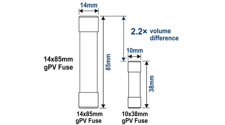
600V DC gPV Fusibles sont couramment utilisés dans les systèmes photovoltaïques résidentiels et commerciaux de petite taille avec des tensions de système allant jusqu'à 600V DC. Ces installations comportent généralement 8 à 12 modules connectés en série (en fonction des spécifications de tension des modules) et représentent la majorité des installations solaires sur les toits. Un fusible de 600 V mesure généralement 10 mm x 38 mm ou 14 mm x 51 mm (dimensions européennes standard) ou peut utiliser des facteurs de forme nord-américains de type lame.
1000V DC gPV Fusibles sont destinés aux installations commerciales et utilitaires fonctionnant à des tensions de système comprises entre 600 et 1 000 V CC. Ces tensions plus élevées permettent des configurations de chaînes plus longues (15-24 modules en général), ce qui réduit les coûts d'équilibre du système en diminuant le nombre de conducteurs de base. La construction physique des fusibles de 1000 V nécessite des chambres d'extinction d'arc plus longues - généralement de 50 à 70 mm - afin de fournir une résistance diélectrique et une capacité d'extinction d'arc adéquates.
1500V DC gPV Fusibles représentent l'état actuel de la technique pour les systèmes photovoltaïques à grande échelle. Le fonctionnement à 1500 V CC permet de configurer des chaînes de 25 à 35 modules en série, ce qui réduit considérablement les coûts de câblage, le nombre de boîtiers de raccordement et la main-d'œuvre d'installation. Ces fusibles utilisent les chambres d'arc les plus longues (80-100 mm ou plus) et des matériaux d'isolation améliorés pour éviter l'embrasement à des tensions élevées.
Le choix de la tension nominale doit tenir compte de la tension en circuit ouvert (Voc) du panneau photovoltaïque à la température ambiante la plus basse prévue. À mesure que la température diminue, le Voc du module augmente, généralement de 0,3% à 0,5% par degré Celsius en dessous des conditions d'essai standard (25°C). Pour un système dont la tension de fonctionnement nominale est de 1000 V DC, des températures de -20°C au petit matin peuvent entraîner des tensions en circuit ouvert proches de 1150 V DC.
La température ambiante affecte de manière significative la capacité de charge des fusibles. Le courant nominal d'un fusible gPV est spécifié à une température de référence standard - généralement 25°C pour les dispositifs homologués IEC et 20°C ou 25°C pour les dispositifs homologués UL. À des températures élevées, l'élément fusible fonctionne plus près de son point de fusion, ce qui réduit le courant supplémentaire nécessaire pour assurer le fonctionnement.
Les fabricants publient des courbes de déclassement en fonction de la température indiquant les facteurs de multiplication à appliquer au courant nominal à différentes températures ambiantes. Une courbe de déclassement typique pour un fusible gPV peut indiquer : à 25°C = 1,00 (courant nominal), à 40°C = 0,95, à 50°C = 0,90, à 60°C = 0,85, à 70°C = 0,78, à 85°C = 0,70.
Pour un fusible gPV de 15A installé dans une boîte de raccordement à une température ambiante de 70°C (courante dans les installations en plein soleil), la capacité effective de transport de courant est de 15A × 0,78 = 11,7A. Si la branche protégée produit 12 A au point de puissance maximale, le fusible subira une contrainte thermique chronique, ce qui pourrait entraîner une défaillance prématurée ou un fonctionnement intempestif.
Pour une application correcte, il faut soit choisir des fusibles plus puissants pour tenir compte du déclassement de la température, soit mettre en œuvre une gestion thermique (ventilation, ombrage, boîtiers dissipateurs de chaleur) pour réduire les températures ambiantes. La norme NEC 690.9(B)(3) exige que les dispositifs de surintensité soient conçus pour fonctionner en continu à 100% du courant disponible après application de tous les facteurs de correction.

Les fusibles gPV remplissent deux fonctions principales de protection dans les systèmes photovoltaïques : la protection au niveau des branches et la protection au niveau des combinateurs. Il est essentiel de comprendre la distinction entre ces applications pour une conception correcte du système et la conformité au code.
Protection au niveau des cordes consiste à installer un fusible en série avec chaque chaîne photovoltaïque avant que les chaînes ne soient mises en parallèle dans une boîte de raccordement. Cette configuration protège contre les défauts d'alimentation inverse, où le courant des branches saines alimente en retour une branche défectueuse. Prenons l'exemple d'une boîte de raccordement avec dix branches en parallèle, chacune étant conçue pour un courant de court-circuit de 10A. Si une branche développe un défaut de mise à la terre ou une défaillance de module, les neuf autres branches peuvent collectivement alimenter la branche défectueuse avec un courant inverse de 90 A, soit neuf fois la capacité de courant prévue de la branche.
Sans fusibles de branche, cette condition d'alimentation inverse pourrait surchauffer les conducteurs, endommager les diodes de dérivation des modules ou enflammer des matériaux combustibles. Les fusibles de branche isolent la branche défaillante, limitant les dommages à un circuit tout en permettant aux neuf autres branches de continuer à produire de l'énergie. Cette isolation sélective améliore la fiabilité globale du système et réduit les pertes de production en cas de défaillance.
La norme NEC 690.9(A) impose une protection contre les surintensités pour les circuits de sources photovoltaïques lorsque trois sources ou plus (branches) sont connectées en parallèle. Pour les systèmes ne comportant que deux branches en parallèle, le courant d'inversion (une branche alimentant une autre) ne peut pas dépasser les valeurs nominales des conducteurs et des composants, de sorte que les fusibles peuvent être facultatifs en fonction des paramètres spécifiques de l'installation.
Protection au niveau du combinateur fournit une protection contre les surintensités pour la sortie combinée de toutes les branches avant la connexion à l'onduleur ou au régulateur de charge. Ce dispositif de protection - qui peut être un fusible gPV ou un fusible Disjoncteur à courant continu-protège les conducteurs entre la boîte de raccordement et l'onduleur contre les surcharges ou les courts-circuits.
L'article 690.9 du Code national de l'électricité établit des exigences spécifiques pour le dimensionnement de la protection contre les surintensités dans les systèmes photovoltaïques. Pour dimensionner correctement les fusibles gPV, il faut comprendre ces exigences et les appliquer systématiquement.
Étape 1 : Déterminer le courant de court-circuit de la branche (Isc)
Le point de départ est la spécification de la fiche technique du module pour le courant de court-circuit. Par exemple, un module typique de 400 W peut avoir un courant de court-circuit (Isc) : 10,5A dans les conditions d'essai standard (STC).
Étape 2 : Appliquer les facteurs de température et d'irradiation
La norme NEC 690.8(A)(1) exige que les courants calculés soient multipliés par 125% pour tenir compte des conditions d'irradiation élevées. Un ciel dégagé peut produire des niveaux d'irradiation allant jusqu'à 1250 W/m², dépassant la valeur standard des conditions de test de 1000 W/m².
Isc ajusté = 10,5A × 1,25 = 13,1A
Étape 3 : Sélection du calibre du fusible
La norme NEC 690.9(B)(1) exige que le dispositif de surintensité ait une valeur nominale d'au moins 156% du courant de court-circuit ajusté :
Valeur minimale du fusible = 13,1A × 1,56 = 20,4A
Par conséquent, sélectionnez le calibre standard suivant au-dessus de 20,4 A, qui serait typiquement un fusible gPV de 25 A.
Cependant, la norme NEC 690.9(B)(2) exige de vérifier que ce calibre de fusible ne dépasse pas la protection maximale contre les surintensités spécifiée par le fabricant du module. Les fiches techniques des modules spécifient généralement les valeurs maximales des fusibles en série, généralement 15A, 20A ou 25A. Si le module spécifie un fusible série maximal de 20 A, mais que les calculs indiquent qu'un fusible de 25 A est nécessaire, le concepteur du système doit soit réduire le nombre de chaînes parallèles pour diminuer le potentiel d'alimentation inverse, soit utiliser des modules dont les fusibles série maximaux sont plus élevés, soit revoir l'architecture du système pour éliminer le conflit de protection.
🎯 Pro Tip : Vérifiez toujours les valeurs maximales des fusibles de série du fabricant de modules avant de finaliser la conception de la boîte combinée. La découverte de conflits de calibres de fusibles au cours de l'installation nécessite une reconception coûteuse du système et peut retarder l'achèvement du projet.
La coordination sélective garantit que seul le dispositif de protection situé immédiatement en amont d'un défaut fonctionne, laissant le reste du système sous tension. Dans les installations photovoltaïques, cela signifie que les fusibles de branche doivent éliminer les défauts au niveau de la branche sans déclencher les disjoncteurs des combinateurs, et que les disjoncteurs des combinateurs doivent éliminer les défauts au niveau des combinateurs sans déclencher la déconnexion principale du système photovoltaïque.
Pour réaliser la coordination sélective, il faut comparer les courbes de temps-courant des dispositifs de protection connectés en série. Pour une coordination sélective, la courbe de temps-courant du dispositif en aval (fusible de branche) doit se situer entièrement à gauche de la courbe du dispositif en amont (disjoncteur de couplage) pour toutes les amplitudes de courant.
Considérons un système avec des fusibles de chaîne de 15 A et un disjoncteur de couplage de 200 A. À un courant de défaut de 200 A (environ 20 fois le calibre de la chaîne), le fusible de 15 A se déclenche en environ 0,05 seconde. Le disjoncteur combiné de 200 A à 200 A (seulement 1 fois son calibre) ne se déclencherait pas instantanément - sa courbe pourrait indiquer plus de 100 secondes pour se déclencher à ce niveau de courant. Une coordination sélective claire existe à cette magnitude de défaut.
Cependant, à des courants de défaut plus élevés approchant les 3 000 A (un défaut boulonné au niveau du bus du combineur), la coordination devient plus difficile. Le fusible de branche s'efface très rapidement (sous-cycle), mais la fonction de déclenchement instantané du disjoncteur peut également fonctionner. Pour assurer une bonne coordination, il faut s'assurer que le temps d'élimination maximal du fusible est inférieur au temps de déclenchement minimal du disjoncteur à tous les niveaux de courant de défaut.
Erreur #1 : Omettre le facteur de dimensionnement 156%
L'erreur la plus fréquente consiste à choisir le calibre des fusibles sur la base de l'Isc du module sans appliquer le facteur de multiplication 156% requis (125% pour des conditions de forte irradiation × 125% pour un fonctionnement continu). Les fusibles sous-dimensionnés subissent une contrainte thermique chronique et une défaillance prématurée, ce qui entraîne des temps d'arrêt du système et des roulements de camions.
Erreur #2 : Ignorer le déclassement de la température
La sélection de calibres de fusibles basés sur des conditions de référence à 25°C sans tenir compte des températures ambiantes réelles de l'installation entraîne des dysfonctionnements ou une dégradation thermique. Il faut toujours appliquer les courbes de déclassement de température du fabricant à la température ambiante maximale prévue.
Erreur #3 : Dépassement du calibre maximal du fusible du module
Même si les calculs du NEC indiquent qu'un fusible plus important est nécessaire, le fait de dépasser le calibre maximal du fusible en série du fabricant du module constitue une violation de la liste et peut annuler les garanties. Cette erreur se produit souvent lorsque les concepteurs mettent en parallèle un trop grand nombre de chaînes sans tenir compte des limites cumulatives du courant d'inversion.
Erreur #4 : Utiliser des fusibles à courant alternatif
Les fusibles CA standard n'ont pas la capacité d'interruption CC et la technologie d'extinction d'arc requises pour les applications photovoltaïques. Bien qu'ils puissent fonctionner dans des conditions normales, ils peuvent tomber en panne de manière catastrophique lorsqu'ils tentent d'interrompre des courants de défaut en courant continu, ce qui peut provoquer des arcs électriques et des incendies.


L'article 690 du code national de l'électricité traite spécifiquement des systèmes photovoltaïques, la section 690.9 établissant des exigences complètes en matière de protection contre les surintensités. La compréhension de ces exigences garantit des installations conformes qui passent l'inspection et fournissent une protection fiable.
NEC 690.9(A) - Circuits et équipements exige que les circuits de source PV, les circuits de sortie PV, les circuits de sortie d'onduleur et les circuits de batterie de stockage soient protégés contre les surintensités. La section précise qu'une protection contre les surintensités est requise lorsque trois circuits sources PV ou plus (branches) sont connectés en parallèle. Cette exigence découle du risque d'inversion de courant lorsque plusieurs branches saines peuvent alimenter une branche endommagée en courant de défaut.
NEC 690.9(B) - Valeurs nominales des dispositifs de surintensité établit la méthodologie de dimensionnement décrite précédemment, exigeant que les dispositifs à maximum de courant soient évalués à au moins 156% du courant maximal disponible. En outre, la sous-section (B)(3) exige que les dispositifs à maximum de courant soient dimensionnés pour un fonctionnement continu à 100% du courant disponible, ce qui nécessite des considérations de déclassement en fonction de la température.
NEC 690.9(C) - Courant continu exige explicitement que les dispositifs de surintensité pour les circuits à courant continu soient répertoriés et prévus pour fonctionner en courant continu à la tension du système. Cette disposition interdit l'utilisation de fusibles et de disjoncteurs à courant alternatif dans les applications photovoltaïques, car ces dispositifs n'ont pas la capacité d'interruption nécessaire en courant continu.
NEC 690.9(D) - Protection contre les surintensités en série s'intéresse au calibre maximal des fusibles en série indiqués sur les modules photovoltaïques. Les installateurs ne doivent pas dépasser le calibre maximal des fusibles spécifié par le fabricant, car cela constitue une violation de l'homologation du module et peut créer des risques d'incendie ou annuler les garanties.
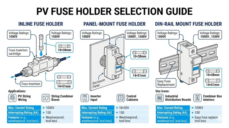
Le système complet de protection contre les surintensités comprend à la fois le fusible et le porte-fusible. Les exigences du NEC et les normes UL établissent des critères spécifiques pour la sélection et l'installation des porte-fusibles.
Valeurs nominales de tension et de courant: Les porte-fusibles doivent être conçus pour une tension et un courant égaux ou supérieurs à ceux des fusibles qu'ils contiennent. Un porte-fusible conçu pour 600 V CC ne peut être utilisé avec des fusibles de 1000 V, même si la tension réelle du système est inférieure à 600 V. Le porte-fusible doit offrir une isolation et une capacité d'interruption de l'arc électrique adéquates pour la tension nominale. Le porte-fusible doit offrir une isolation et une capacité d'interruption d'arc adéquates pour la tension nominale.
Compatibilité de l'évaluation des interruptions: La norme UL 2579 exige que les fusibles soient testés en combinaison avec les porte-fusibles prévus, créant ainsi des “systèmes” fusibles/porte-fusibles aux performances vérifiées. L'utilisation de fusibles dans des porte-fusibles non compatibles peut compromettre l'indice d'interruption, car la résistance mécanique du porte-fusible et les caractéristiques de confinement de l'arc ont une incidence sur les performances globales.
Conception à sécurité tactile: Les porte-fusibles situés dans des endroits accessibles doivent être dotés de connexions à sécurité tactile qui empêchent tout contact accidentel avec les bornes sous tension lors du remplacement des fusibles. Cela nécessite généralement des bornes encastrées ou des couvercles isolants qui restent en place lorsque les fusibles sont retirés.
Notations environnementales: Les coffrets combinés extérieurs nécessitent des porte-fusibles avec des classements NEMA ou IP appropriés pour la protection de l'environnement. Les boîtiers NEMA 3R (étanche à la pluie) ou NEMA 4X (étanche à l'eau, résistant à la corrosion) sont typiques pour les installations sur le toit et au sol.
L'article 690 du NEC établit des exigences spécifiques pour l'emplacement des dispositifs de surintensité dans les systèmes photovoltaïques. Ces exigences établissent un équilibre entre l'accessibilité pour la maintenance et la protection contre les risques environnementaux et les accès non autorisés.
NEC 690.9(E) - Emplacement exige que les dispositifs de protection contre les surintensités soient facilement accessibles, sauf en cas d'exemption spécifique. L'expression “facilement accessible” signifie qu'il est possible d'y accéder rapidement sans avoir à utiliser une échelle, à enlever des obstacles ou à déverrouiller des portes (définition de l'article 100 du NEC). Cette exigence garantit que les fusibles peuvent être remplacés et inspectés sans effort extraordinaire.
Cependant, les systèmes photovoltaïques nécessitent souvent des boîtes de raccordement sur le toit contenant des fusibles de chaîne. L'exception NEC 690.9(E) permet de placer des dispositifs de surintensité sur les toits ou dans d'autres endroits moins accessibles lorsque les dispositifs sont : (1) à portée de vue et à moins de 1,8 mètre (6 pieds) de l'équipement qu'ils protègent, (2) correctement identifiés, (3) faisant partie d'ensembles d'équipement répertoriés.
Emplacement du fusible de la corde: Les fusibles de branche doivent être placés au point où les branches individuelles sont parallèles, généralement dans une boîte de combinaison près du réseau. Le fait de placer les fusibles trop loin de l'installation crée des parcours de conducteurs non protégés, vulnérables aux dommages physiques ou aux défauts de mise à la terre.
Un étiquetage correct est essentiel pour assurer la sécurité de la maintenance et des interventions d'urgence. L'article 690 du NEC établit des exigences complètes en matière d'étiquetage pour les systèmes photovoltaïques, y compris des exigences spécifiques pour les dispositifs de protection contre les surintensités.
NEC 690.13 - Moyens de déconnexion des systèmes photovoltaïques exige des étiquettes permanentes identifiant les moyens de déconnexion et les dispositifs de surintensité. Les étiquettes doivent indiquer la tension maximale du système, le courant de défaut maximal disponible et la date d'installation ou de calcul du courant de défaut maximal.
Étiquetage des boîtes de combinaisons doit comprendre les éléments suivants : “AVERTISSEMENT : SOURCE D'ALIMENTATION PHOTOVOLTAIQUE” en lettres réfléchissantes, la tension du système et les marques de polarité, le nombre de branches protégées, les valeurs nominales des fusibles et les numéros des pièces de rechange, et l'avertissement de risque d'éclair d'arc électrique avec le niveau d'énergie incident et les exigences en matière d'équipement de protection individuelle.
Étiquetage des porte-fusibles: Les positions individuelles des fusibles doivent être étiquetées avec : l'identifiant de la chaîne (par exemple, “Chaîne 1”, “Chaîne 2”, etc.), le calibre et le type de fusible (par exemple, “15A gPV 1000V DC”), et la correspondance avec l'emplacement de la matrice pour le dépannage.

Problème : Installer des fusibles standard en courant alternatif dans des circuits photovoltaïques en courant continu sans vérifier la capacité d'interruption en courant continu.
Scénarios courants :
- Utilisation de fusibles CA facilement disponibles en tant que remplacements “temporaires”.
- En supposant que la tension nominale de 600V AC est égale à la capacité de 600V DC
- Installation de fusibles automobiles ou industriels standard dans des applications solaires
- Achat de fusibles non listés auprès de fournisseurs de matériel électrique général
Correction : Vérifiez toujours les valeurs nominales explicites de tension continue et la certification UL 2579 ou IEC 60269-6 de tous les fusibles utilisés dans les systèmes photovoltaïques. Les fusibles classés AC ne disposent pas de la technologie d'extinction d'arc améliorée requise pour l'extinction de l'arc DC et peuvent maintenir un arc dangereux dans des conditions de défaut, créant ainsi des risques d'incendie. Remplacez immédiatement tous les fusibles à courant alternatif par des fusibles gPV correctement certifiés correspondant aux exigences de tension et de courant du système.
Problème : Utiliser des fusibles dont la tension nominale est inférieure à la tension maximale en circuit ouvert du système, en particulier dans des conditions de température froide.
Scénarios courants :
- Utilisation de fusibles de 600 V dans des systèmes approchant la tension nominale de 600 V
- Absence de prise en compte des augmentations de température à froid Voc selon NEC 690.7
- En supposant que la tension nominale du système est égale à la tension maximale du système
- Ignorer les facteurs de correction de la tension à froid du fabricant
Correction : Calculer la tension maximale du système en utilisant les facteurs de correction de température à froid NEC 690.7(A). Choisir des fusibles dont la tension nominale dépasse la tension maximale calculée d'une marge de sécurité d'au moins 20%. Pour les systèmes approchant les 1000V maximum, spécifier des fusibles de 1500V pour fournir une marge adéquate. Vérifier que la tension nominale des fusibles tient compte de la température ambiante la plus basse prévue sur le lieu d'installation.
Problème : Installer des fusibles dont le pouvoir de coupure (taux d'interruption) est inférieur au courant de défaut disponible à l'emplacement de l'installation.
Scénarios courants :
- Utilisation de fusibles de 10 kA dans les systèmes à grande échelle présentant des courants de défaut plus élevés
- Absence de calcul du courant de défaut disponible pour toutes les chaînes parallèles
- Ignorer le retour potentiel de l'onduleur en cas de défaut à la terre
- Sélection des fusibles sur la base du seul courant nominal sans vérification de la capacité d'interruption
Correction : Calculer le courant de défaut disponible à chaque emplacement du dispositif de protection en tenant compte de toutes les sources parallèles. Pour les fusibles de branche, calculer (N-1) × Isc ajusté où N est le nombre de branches en parallèle. Choisir des fusibles dont le pouvoir d'interruption dépasse les valeurs calculées d'au moins 20%. Les installations à grande échelle requièrent généralement des fusibles de 20 kA ou 30 kA ; les systèmes résidentiels requièrent généralement un minimum de 10 kA.
Problème : Sélection des calibres de fusibles sur la base de conditions de référence à 25°C sans appliquer les facteurs de déclassement de la température pour l'environnement d'installation réel.
Scénarios courants :
- Installation de boîtes de raccordement en plein soleil sans gestion thermique
- Ne pas mesurer les températures ambiantes réelles pendant les heures d'ensoleillement maximal
- En supposant que les conditions de référence standard de 25°C s'appliquent aux installations extérieures
- Utiliser des calibres de fusibles qui semblent adéquats sur le papier mais qui ne fonctionnent pas dans les conditions réelles.
Correction : Mesurer ou estimer les températures internes maximales de la boîte de raccordement pendant les périodes d'ensoleillement maximal (généralement de 60 à 85 °C). Appliquer les courbes de déclassement de la température du fabricant aux calibres de fusibles sélectionnés. Choisir des fusibles de calibre supérieur pour maintenir une capacité adéquate après déclassement, ou mettre en œuvre une gestion thermique (ventilation, ombrage, revêtements réfléchissants) pour réduire les températures ambiantes. Documenter les calculs de déclassement dans les dossiers de conception du système.

Les fusibles à courant continu diffèrent des fusibles à courant alternatif par leur tension nominale, leur capacité à interrompre l'arc et l'espacement des contacts. Le courant continu crée des arcs soutenus pendant l'interruption car il ne traverse pas naturellement le zéro comme le courant alternatif. Les fusibles à courant continu intègrent des espaces de contact plus importants, des goulottes d'arc améliorées avec un remplissage de sable de silice et des corps céramiques spécialisés pour interrompre en toute sécurité les défauts de courant continu.
Un fusible de 600 V CA ne peut supporter en toute sécurité que 300 à 400 V CC en raison des problèmes d'arc soutenus dans les circuits CC. La chambre d'extinction de l'arc dans les fusibles à courant continu est généralement de 50 à 100 mm de long, ce qui est nettement plus long que pour les fusibles à courant alternatif. Vérifiez toujours les tensions nominales explicites en courant continu et la certification UL 2579 ou IEC 60269-6 plutôt que de supposer que les composants en courant alternatif fonctionnent pour les applications en courant continu.
Commencez par le courant de court-circuit de la fiche technique du module (Isc). Appliquer le facteur de rayonnement élevé NEC 690.8(A)(1) : Isc ajusté = Isc × 1,25. Appliquer ensuite l'exigence de dimensionnement NEC 690.9(B)(1) : Calibre minimum du fusible = Isc ajusté × 1,56.
Sélectionnez le calibre de fusible standard suivant au-dessus de ce minimum calculé. Par exemple, si Isc = 10,5A, alors Isc ajusté = 13,1A, et fusible minimum = 20,4A, sélectionnez un fusible de 25A. Vérifiez que ce calibre ne dépasse pas le calibre maximal des fusibles de série du fabricant du module (généralement indiqué sur la fiche technique). Enfin, appliquez un déclassement de température pour votre environnement d'installation afin de garantir une capacité adéquate.
Un surdimensionnement modéré (sélection du calibre standard suivant au-dessus du minimum calculé) est acceptable et offre une marge pour les variations de température. Cependant, un surdimensionnement important des fusibles compromet l'efficacité de la protection. Vous ne devez pas dépasser le calibre maximal des fusibles de série du fabricant du module, conformément à la norme NEC 690.9(D) - cela constitue une violation de la liste des modules et peut entraîner l'annulation des garanties.
Par exemple, si les calculs indiquent un minimum de 20,4 A, la sélection d'un fusible de 25 A est appropriée. La sélection d'un fusible de 32 ou 40 A alors qu'un fusible de 25 A est nécessaire retarderait le fonctionnement en cas de surcharge, ce qui risquerait d'endommager les composants avant que le fusible n'agisse. Vérifiez toujours que le calibre sélectionné offre une protection adéquate aux composants en aval, en particulier aux diodes de dérivation des modules.
Le pouvoir de coupure doit être égal ou supérieur au courant de défaut disponible sur le lieu d'installation. Pour les systèmes résidentiels (2 à 12 chaînes parallèles), un pouvoir de coupure de 10 kA est généralement suffisant. Les systèmes commerciaux (12 à 30 chaînes parallèles) doivent utiliser des fusibles de 15 kA ou 20 kA.
Les installations à grande échelle avec plusieurs onduleurs et des schémas de mise à la terre complexes peuvent nécessiter des valeurs nominales de 30 kA. Calculer le courant de défaut disponible comme (N-1) × Isc ajusté, où N est le nombre de branches en parallèle. Ajouter une marge de sécurité de 20% pour tenir compte des variations et de la rétroaction potentielle de l'onduleur en cas de défaut de mise à la terre.
Effectuer des inspections visuelles annuelles pour vérifier que les porte-fusibles et les connexions ne sont pas décolorés, corrodés ou endommagés par la chaleur. Lors de la mise en service du système et de l'entretien annuel, inclure les boîtes de combinaisons dans les scans thermiques - des températures élevées au niveau des porte-fusibles (plus de 10°C au-dessus des porte-fusibles adjacents) indiquent des connexions à haute résistance nécessitant une attention particulière.
Inspecter les fusibles après un coup de foudre à proximité du réseau ou après toute défaillance du système. Remplacer tout fusible qui a fonctionné (grillé) par un fusible de même calibre et de même type. Vérifier chaque année les spécifications du couple de serrage des bornes, car les cycles thermiques peuvent desserrer les connexions au fil du temps. Dans des conditions de fonctionnement normales, les fusibles gPV ont une durée de vie indéfinie s'ils ne sont pas soumis à des courants de défaut.
L'indice I²t (prononcé “eye-squared-tee”) quantifie l'énergie thermique qui traverse un fusible avant qu'il n'élimine un défaut. Chaque composant électrique a un seuil de dommage thermique ; pour être protégé, l'I²t d'élimination du fusible doit être nettement inférieur à l'I²t de résistance du composant protégé.
Les diodes de dérivation des modules ont généralement une résistance I²t de 2 000 à 10 000 A²s. L'I²t d'élimination du fusible de protection gPV aux courants de défaut prévus doit être inférieur d'au moins 50% à cette valeur. Par exemple, si une diode de dérivation résiste à 8 000 A²s, l'I²t d'élimination du fusible ne doit pas dépasser 4 000 A²s. Demandez les courbes de données I²t du fabricant lorsque vous spécifiez des fusibles pour des applications critiques avec des composants coûteux tels que des micro-onduleurs ou des optimiseurs de courant continu.
Une installation correcte nécessite des tournevis dynamométriques calibrés ou des clés dynamométriques réglées selon les spécifications du fabricant. La plupart des porte-fusibles spécifient un couple de serrage des bornes de 7 à 15 Nm, qui varie en fonction de la taille du conducteur et de la conception de la borne. Les tournevis standard ne permettent pas d'obtenir de manière fiable un couple de serrage correct, ce qui entraîne soit des connexions lâches qui surchauffent, soit des bornes trop serrées qui endommagent les composants.
Les outils supplémentaires comprennent des pinces à dénuder pour les conducteurs de calibre 10-4 AWG, des outils de sertissage pour les conducteurs torsadés (améliorant la fiabilité des contacts) et un équipement d'étiquetage approprié pour l'identification des circuits. Les outils permettent d'éviter les défaillances de connexion nécessitant un dépannage et des travaux de reprise qui dépassent de loin l'investissement dans l'outil.
La sélection, la spécification et l'installation correctes des fusibles gPV représentent des étapes critiques dans la conception des systèmes photovoltaïques qui ont un impact direct sur la sécurité, la fiabilité et les performances à long terme. Contrairement à la protection contre les surintensités en courant alternatif, les applications photovoltaïques en courant continu présentent des défis uniques nécessitant des composants spécialisés conçus pour l'interruption de l'arc en courant continu, les conditions environnementales extrêmes et les caractéristiques de défaut spécifiques des sources photovoltaïques à courant limité.
Le choix entre les fusibles certifiés IEC 60269-6 et UL 2579 dépend principalement de l'emplacement du projet, des codes applicables et des paramètres de conception du système. Les deux normes de certification établissent des exigences d'essai rigoureuses garantissant une capacité d'interruption fiable du courant continu, bien que leurs séries de tension nominale, leurs classes de pouvoir de coupure et leurs exigences de marquage diffèrent de manière significative.
Les critères de sélection technique vont au-delà de l'adéquation entre le courant nominal du fusible et le courant de la chaîne. Une application correcte nécessite une évaluation systématique des tensions nominales tenant compte des augmentations de température à froid, du pouvoir de coupure adapté à toutes les sources parallèles, des facteurs de déclassement en fonction de la température reflétant les conditions d'installation réelles, et de la coordination de l'I²t garantissant la protection des composants.
Ressources connexes :
Complétez votre compréhension de Fusibles DC avec les éléments de protection correspondants :
- Disjoncteurs DC pour systèmes solaires - Protection alternative contre les surintensités réinitialisables
- Protection contre la foudre DC SPD - Protection contre les surtensions fonctionnant avec des fusibles
- Conception d'une boîte de raccordement PV - Intégration complète des fusibles, des disjoncteurs et des SPD
- Interrupteurs-sectionneurs DC - Dispositifs d'isolation pour un remplacement sûr des fusibles
Prêt à spécifier des fusibles gPV conformes pour votre installation solaire ? Contactez l'équipe technique de SYNODE pour obtenir des recommandations spécifiques à votre projet en fonction de la tension de votre système, de la configuration de votre chaîne et des conditions environnementales. Nous veillons à ce que le choix des fusibles soit conforme aux exigences du NEC et aux normes de sécurité pour des systèmes de protection photovoltaïques fiables.
Dernière mise à jour : Novembre 2025
Auteur : L'équipe technique de SYNODE
Révisé par : Département de génie électrique