Adresse
304 North Cardinal
St. Dorchester Center, MA 02124
Heures de travail
Du lundi au vendredi : de 7h00 à 19h00
Le week-end : 10H00 - 17H00
Adresse
304 North Cardinal
St. Dorchester Center, MA 02124
Heures de travail
Du lundi au vendredi : de 7h00 à 19h00
Le week-end : 10H00 - 17H00

Protecting solar systems from lightning requires a systematic approach combining structural lightning protection equipment with surge protection devices and proper grounding—not just hoping your system avoids strikes.
Lightning poses three distinct threats to photovoltaic installations: direct strikes that physically destroy components, conducted surges that damage electronics through wiring, and electromagnetic pulses that induce voltages in cables. Each threat requires specific protection equipment installed according to proven methods.
This guide walks you through every piece of equipment needed for comprehensive lightning protection and explains exactly how to install each component. You’ll learn what to buy, where to place it, how to connect everything properly, and how to verify protection effectiveness using industry-standard methods.
💡 Key Insight: Complete lightning protection isn’t a single device—it’s a coordinated system of air terminals, conductors, surge protectors, and grounding working together. Installing only surge protectors or only structural protection leaves critical vulnerabilities that lightning will exploit.
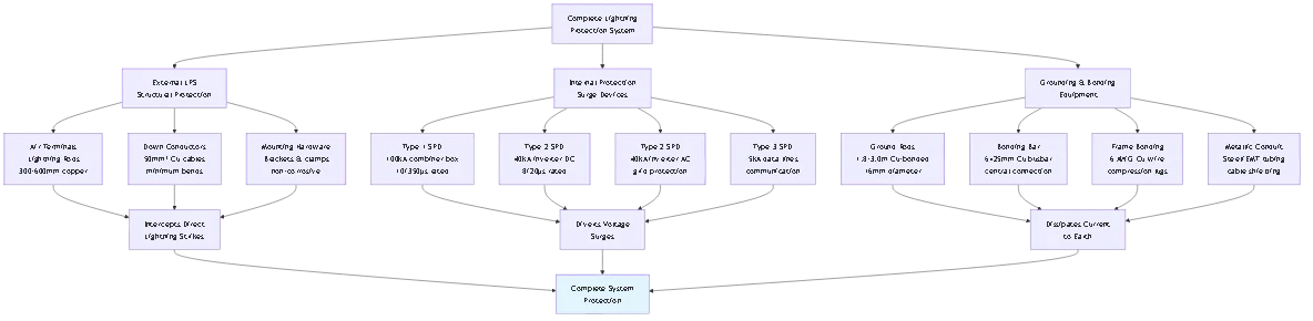
Lightning protection systems consist of three integrated subsystems working together. Understanding what each component does helps you specify appropriate equipment for your installation.
Air Terminals (Lightning Rods):
These are the pointed metal rods that intentionally attract lightning strikes, intercepting them before they hit solar panels or building structures. Modern air terminals use the “early streamer emission” principle or traditional Franklin rod design.
What you need: Copper or aluminum rods 300-600mm long, mounted 300-600mm above the highest point of your solar array. For arrays larger than 400m², install multiple air terminals spaced 15-20 meters apart.
Down Conductors (Lightning Cables):
These heavy-gauge cables carry lightning current from air terminals to the ground electrode system. They must follow the shortest practical path to earth with minimal bends.
What you need: Copper conductor minimum 50mm² cross-section (6 AWG) or aluminum 70mm² (4 AWG). Commercial systems need 95mm² copper (3/0 AWG). One down conductor per air terminal, maximum 20m spacing between conductors.
Ground Electrode System:
The termination point where lightning current dissipates into earth. Multiple ground rods or buried conductors create low-resistance paths to earth.
What you need: Copper-bonded steel ground rods 1.8-3.0m long, minimum 16mm diameter. Install 2-4 rods per down conductor, spaced 2× rod length apart. Target ground resistance <10Ω (measure with earth resistance tester).
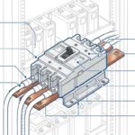
Type 1 SPDs (Primary Protection):
Installed at the first point where lightning current might enter—typically at array combiner boxes for ground-mount systems or service entrance for building-integrated arrays.
What you need: DC-rated Type 1 SPD with 100kA discharge capacity (10/350μs waveform), MCOV rating 1.15× system Voc. One SPD per positive and negative DC line. Include thermal disconnector and visual failure indicator.
Type 2 SPDs (Secondary Protection):
Installed at inverter DC inputs and AC outputs to protect sensitive electronics from conducted surges that bypass or overwhelm Type 1 protection.
What you need: DC-rated Type 2 SPD with 40-65kA discharge capacity (8/20μs waveform) for DC side. AC-rated Type 2 with 40-65kA for inverter output. Install within 30cm of protected equipment terminals.
Type 3 SPDs (Final Protection):
Protect communication lines and control circuits from voltage transients. These small devices install directly at equipment terminals.
What you need: Type 3 SPD rated for data line voltage (typically 24V or 48V) with RJ45, USB, or RS485 connectors matching your monitoring equipment. Maximum 5kA discharge capacity sufficient.
Equipotential Bonding Bar:
Central connection point where all grounding conductors, panel frames, and metal structures connect together, eliminating voltage differences during lightning events.
What you need: Copper or tin-plated copper busbar, minimum 6mm thick × 25mm wide × length matching number of connections. Mount on insulated standoffs near main grounding point.
Panel Frame Bonding Conductors:
Connect each solar panel’s aluminum frame to the racking system and bonding bar, ensuring no isolated metal that could develop dangerous voltages.
What you need: 6 AWG bare copper wire with listed compression lugs or bonding clips. One connection per panel or per section (every 3-4 panels). Use star-washers and anti-oxidant compound on aluminum connections.
Cable Shielding and Armor:
Reduces electromagnetic coupling into DC and AC cables from nearby lightning strikes, preventing induced voltages from damaging equipment.
What you need: Metallic conduit (rigid steel or EMT) for DC wiring runs exceeding 10 meters. For flexible applications, use armored MC cable or shielded solar cable with grounded metal braid.
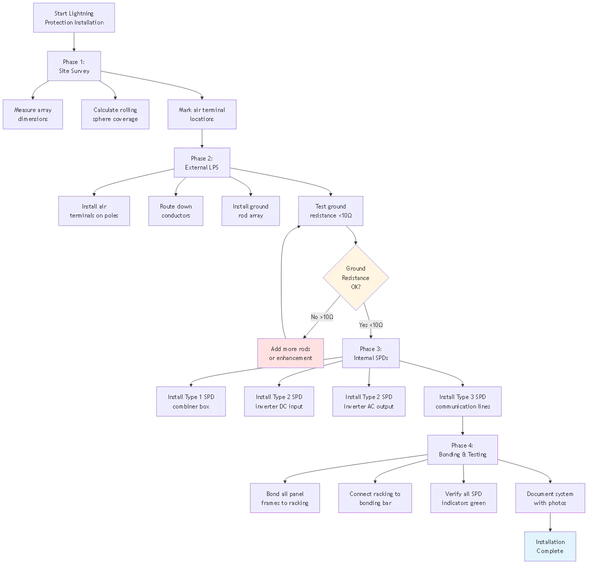
Before installing any equipment, map your solar array and calculate required air terminal placement using the rolling sphere method or protective angle method.
Rolling Sphere Method:
Imagine rolling a sphere of radius R over your installation. Any point the sphere touches needs protection. For solar arrays, use R = 45 meters (IEC 62305 Level III protection).
Procédure :
– Measure array dimensions and roof/ground elevation
– Identify highest points of array (typically corners and center)
– Calculate protective zones using 45m sphere radius
– Mark air terminal locations ensuring complete coverage
Exemple : 20m × 15m ground-mount array requires 4 air terminals at corners plus 1 center terminal to ensure no point exceeds 45m from nearest air terminal. Total: 5 air terminals.
🎯 Conseil de pro: Use free software like “LPS Design Tool” or “Lightning Protection Calculator” to visualize rolling sphere coverage. These tools generate 3D models showing protection zones and identify vulnerable areas requiring additional air terminals.
Air terminals must be mechanically secure and electrically bonded to down conductors. Installation method depends on mounting surface and structural requirements.
For Ground-Mount Arrays:
Install air terminals on dedicated poles positioned 2-3 meters from array edges, extending 1-2 meters above panel height. This keeps lightning current path away from DC wiring.
Materials needed:
– 3-meter galvanized steel or aluminum poles (schedule 40 pipe)
– 600mm copper air terminals with threaded bases
– Concrete footings 300mm diameter × 600mm deep
– Pole mounting brackets with U-bolts
– Stainless steel hardware (all connections)
Installation steps:
1. Dig footings at marked locations, 600mm deep
2. Set poles in concrete, plumb and level using laser level
3. Allow 48-hour concrete cure before proceeding
4. Thread air terminals into pole tops, torque to 40-50 N⋅m
5. Connect down conductor to air terminal base using compression lug
For Rooftop Arrays:
Mount air terminals to array racking or building structure using listed mounting brackets that penetrate weatherproof membranes with proper sealing.
Critical requirements:
– Penetrations must use listed roof flashing assemblies
– Maintain 300mm minimum clearance between air terminals and solar panels
– Bond air terminal mounting brackets to array frame
– Use expansion joints if mounting to different roof sections
Down conductors carry lightning current from air terminals to ground electrodes. Route them to minimize length and sharp bends while maintaining mechanical protection.
Routing Guidelines:
Run down conductors vertically with minimal horizontal runs. Each bend adds inductance that increases voltage during lightning events. Maximum bend radius should be 200mm (8 inches).
For Ground-Mount Systems:
– Route conductors down support poles internally if possible
– Use PVC conduit only for mechanical protection below grade
– Above-grade conductors need UV-resistant jacketing
– Maintain 1 meter separation from DC cables
For Rooftop Systems:
– Route along roof edges using listed stand-off brackets every 1 meter
– Cross roof surfaces using elevated cable trays (minimum 100mm above surface)
– Enter building through dedicated penetrations (not with electrical conduits)
– Run down exterior walls to ground level
Connection Methods:
All conductor connections use exothermic welding (Cadweld) or listed mechanical compression connectors—never solder or wire nuts for lightning conductors.
Best practice: Compression lugs with 4-bolt connections, torqued to 20 N⋅m, with anti-oxidant compound on all aluminum-to-copper transitions.
Ground electrodes dissipate lightning current into earth. Installation quality determines overall system effectiveness—poor grounding renders expensive air terminals and SPDs useless.
Ground Rod Installation:
Drive copper-bonded steel rods vertically into earth using listed driving tools. Angled installations (up to 45°) acceptable only when rock prevents vertical driving.
Spacing Requirements:
– Minimum 2 rods per down conductor
– Rod spacing = 2× rod length (e.g., 2.4m rods need 4.8m spacing)
– Form array or ring configuration for multiple rods
– Connect rods with bare copper conductor (50mm²)
Installation Steps:
1. Mark rod locations per design drawings
2. Drive rods using jackhammer with driving adapter or manual post driver
3. Leave 150mm (6 inches) exposed above grade for connections
4. Connect rods using exothermic welds or listed clamps
5. Route connection to down conductor compression lug
6. Backfill and compact soil around rods
Ground Resistance Testing:
After installation, measure resistance using 3-wire or 4-wire earth resistance tester (not standard multimeter). Target <10Ω for effective lightning protection.
If resistance exceeds 10Ω:
– Add more ground rods to array (each additional rod reduces resistance ~30%)
– Use chemical ground enhancement (bentonite or conductive concrete)
– Install ground ring (buried bare copper around array perimeter)
– Extend ground rods deeper (3m or 4.5m lengths)

Type 1 SPDs protect against lightning current entering through the DC array. Install at the first junction point where multiple strings combine—typically the combiner box for ground-mount or large rooftop systems.
Mounting Location:
Install SPDs inside combiner box enclosure on DIN rail or mounting plate. For outdoor combiner boxes, use IP65-rated SPDs in NEMA 4X enclosures.
Wiring Procedure:
Type 1 SPDs install in parallel with DC lines, between positive/negative conductors and ground.
Step-by-step wiring:
1. De-energize system – Open DC disconnect, verify zero voltage with multimeter
2. Identify DC polarity – Mark positive (red) and negative (black) bus bars
3. Mount SPD – Secure device to DIN rail, maintain 50mm spacing from other equipment
4. Connect DC inputs – Run 6 AWG from positive busbar to SPD “+” terminal, torque to manufacturer spec (typically 3-5 N⋅m)
5. Connect DC negative – Run 6 AWG from negative busbar to SPD “−” terminal, same torque
6. Connect ground – Run 6 AWG from SPD ground terminal to main bonding bar, use shortest possible path (<1 meter) 7. Verify polarity – Double-check positive/negative connections before energizing
8. Check indicators – After energizing, verify SPD green/OK indicator illuminated
⚠️ Avertissement: SPD ground lead length is critical. Each meter of wire adds ~1μH inductance that reduces protection effectiveness by ~1kV per meter. Keep total positive + negative + ground lead length under 1 meter combined.
Coordination with Other SPDs:
When using both Type 1 and Type 2 SPDs, maintain minimum 10-meter cable distance between them for proper coordination. If closer installation required, use manufacturer-coordinated SPD sets.
Type 2 SPDs provide equipment-level protection directly at inverter terminals. Most modern inverters include integrated SPDs, but external high-capacity devices offer superior protection.
Inverter DC Input Protection:
Install external Type 2 SPD between DC disconnect and inverter DC terminals when:
– Inverter built-in SPD rated <20kA (check specifications) – DC cable run exceeds 30 meters from combiner to inverter – Installation in high-lightning-risk area (>25 strikes/km²/year)
– Building insurance requires IEC 62305-compliant protection
Installation Method:
For string inverters with multiple DC inputs, install one SPD per string input or one high-capacity SPD across all strings at common bus.
Wiring Steps:
1. Mount Type 2 SPD on wall near inverter or inside inverter enclosure if space permits
2. Connect SPD positive terminal to DC positive bus using 6 AWG with compression lug
3. Connect SPD negative terminal to DC negative bus, same wire gauge
4. Run 6 AWG ground wire to inverter grounding point (equipment ground bus)
5. Keep all three leads (+, −, ground) as short as possible, bundled together to minimize loop area
6. Torque all connections per manufacturer specifications
7. Verify indicator shows operational status
Lead Length Optimization:
For inverters with DC terminals on bottom, mount SPD directly below terminals, minimizing lead length to 20-30cm total. This provides maximum protection effectiveness.
AC-side protection prevents utility grid surges from damaging inverter output stages and protects connected loads from voltage transients.
AC SPD Selection by System Type:
- Single-phase residential (120/240V): Type 2, 40-65kA, 2-pole SPD
- Three-phase commercial (208Y/120V or 480Y/277V): Type 2, 65kA, 3-pole + neutral SPD
- With ground fault protection: SPD with N-PE disconnector to prevent nuisance RCD trips
Installation Location Options:
Option 1 – At Inverter AC Terminals:
Install SPD in dedicated junction box mounted adjacent to inverter, connecting AC output wires before they enter building distribution system. Provides best protection for inverter electronics.
Option 2 – At Main AC Panel:
Install SPD in main distribution panel on dedicated breaker. Protects entire building but offers less protection for inverter itself due to longer conductor runs.
Recommended: Use both locations for comprehensive protection—Type 2 at inverter (40kA) coordinated with Type 2 at panel (65kA).
Wiring for Single-Phase SPD:
1. Mount SPD near inverter AC output or in main panel on DIN rail
2. Connect black/red AC wires to SPD L1/L2 terminals (40A breaker on feed side)
3. Connect white neutral to SPD N terminal
4. Connect green/bare ground to SPD ground terminal
5. Bond SPD ground to panel ground bus or inverter ground point
6. Verify all connections tight (10 N⋅m torque for AC terminals)
7. Energize and check SPD status indicator
Modern inverters communicate through Ethernet, RS485, WiFi, or cellular connections. These data lines create lightning entry paths that bypass DC/AC SPDs.
Communication Line Protection Points:
Install Type 3 SPDs at:
– Ethernet cables between inverter and router (outdoor cable runs)
– RS485 daisy-chains connecting multiple inverters
– External WiFi antennas mounted on roofs
– Cellular modem connections to monitoring systems
Installation for Ethernet (RJ45) Connections:
Use inline RJ45 SPD devices that install between cable segments.
Procédure :
1. Disconnect Ethernet cable from inverter monitoring port
2. Plug cable into SPD “line” or “input” port
3. Use short patch cable (<0.5m) from SPD “equipment” port to inverter 4. Connect SPD ground wire to inverter chassis ground using #10-32 screw 5. Verify link lights show successful connection 6. Test monitoring connection to confirm data passing through SPD For RS485 Connections:
Install terminal-block style SPD in series with communication wiring.
Wiring steps:
1. Cut RS485 twisted pair at convenient splice point
2. Strip wire ends, tin with solder
3. Connect A+ wire to SPD terminal A
4. Connect B− wire to SPD terminal B
5. Connect shield drain wire to SPD ground terminal
6. Ground SPD to nearest equipment ground point
7. Verify communication with logic probe (differential voltage 2-5V typical)
The bonding bar serves as the central star-point connection where all ground conductors, panel frames, equipment grounds, and LPS components connect together.
Bonding Bar Specifications:
Use solid copper or tin-plated copper busbar, minimum 6mm thick × 25mm wide. Length depends on number of connections—allow 50mm spacing per connection point.
Mounting Location:
Install bonding bar near the main grounding electrode system connection, typically:
– At inverter location (for rooftop systems)
– At combiner box (for ground-mount systems)
– At main distribution panel (for building-integrated systems)
Installation Steps:
1. Mount bonding bar on insulated standoffs attached to wall or enclosure
2. Use minimum 16mm (5/8″) spacing between bar and mounting surface
3. Connect bonding bar to main grounding electrode conductor (50mm² minimum)
4. Bring all ground conductors to bar in star configuration (no daisy-chaining)
5. Use listed bonding lugs, one per connection, torqued per manufacturer spec
6. Label each connection with wire tag identifying source
Connections to Bonding Bar:
– Down conductor grounds from air terminals
– Ground electrode conductor from rod array
– SPD ground conductors (Type 1, 2, and 3)
– Solar panel frame bonding conductors
– Inverter equipment ground
– Metallic conduit bonds
– Racking system ground
Every solar panel frame must connect to the grounding system to prevent voltage differences between panels during lightning events.
Bonding Methods:
Method 1 – Individual Panel Bonding:
Run 6 AWG copper wire from each panel’s bonding hole (pre-drilled ground point) to racking system using bonding clips or lugs.
Method 2 – Shared Bonding Straps:
Use listed bonding straps that span multiple panels, connecting frames together and to racking in sections of 3-4 panels.
Installation Procedure:
1. Clean all connection surfaces with wire brush to remove oxidation
2. Apply anti-oxidant compound (NOALOX or similar) to aluminum frame connections
3. Install bonding lug or clip at panel bonding point
4. Connect 6 AWG bare copper wire to lug, torque to 3-5 N⋅m
5. Route wire to racking rail without sharp bends
6. Connect to racking using stainless steel star washer and bolt
7. Verify metal-to-metal contact (no paint or anodizing between surfaces)
8. Test continuity from panel frame to bonding bar (<1Ω resistance)
🎯 Conseil de pro: For large arrays with 100+ panels, use listed bonding systems with copper tape or wire-management channels integrated into racking. These pre-engineered solutions ensure code compliance and reduce installation time by 50-70% compared to individual wire runs.
The metal racking structure must bond to the main bonding bar to prevent it from becoming energized during lightning events.
Racking Bonding Requirements:
Each racking rail section requires bonding connection every 10 meters maximum. For ground-mount systems, also bond racking post foundations to ground rod array.
Connection Method:
1. Drill and tap bonding hole in racking rail if not pre-drilled
2. Install 6 AWG copper bonding wire from rail to next rail or to bonding bar
3. Use stainless steel bolts with star washers to ensure gas-tight connection
4. For aluminum racking on steel support posts, use bimetallic connectors
5. Bond rail-to-rail connections across expansion joints
6. Connect racking to bonding bar using 6 AWG minimum conductor
Ground-Mount Post Grounding:
For systems on driven posts or concrete foundations, provide supplemental grounding:
– Drive 1.2m ground rods at corner posts
– Bond posts to rods using 6 AWG copper
– Connect post ground array to main ground electrode system
– Creates ground grid under array reducing step potential
Ground resistance testing verifies that your electrode system can dissipate lightning current effectively. Testing must use proper instruments—standard multimeters cannot measure ground resistance.
Required Equipment:
Use 3-wire or 4-wire earth resistance tester (Megger, Fluke, or equivalent). These instruments inject known current and measure voltage drop to calculate resistance.
Three-Wire Testing Procedure:
This is the most common method for solar installations.
Setup:
1. Disconnect down conductor from ground electrode being tested (isolation required)
2. Drive two test stakes into earth: P1 stake at 20 meters, P2 at 40 meters from ground electrode
3. Connect tester E terminal to ground electrode under test
4. Connect tester P terminal to P1 stake (voltage probe)
5. Connect tester C terminal to P2 stake (current probe)
6. Verify all connections tight and test stakes driven to minimum 300mm depth
Test Execution:
1. Power on tester, select 3-wire mode
2. Press test button, wait for reading to stabilize (10-30 seconds)
3. Record resistance value (target <10Ω) 4. Move P1 stake ±2m in both directions, retest 5. If readings vary <10%, test is valid 6. If readings vary >10%, soil conditions are interfering—use 4-wire method
If Resistance Exceeds 10Ω:
Option 1 – Add Ground Rods:
Install additional rods spaced 2× rod length apart, connecting with bare copper conductor. Each rod reduces total resistance by ~25-30%.
Option 2 – Chemical Enhancement:
– Pour 20kg bentonite clay around each ground rod
– Mix with water to form slurry that fills rod hole
– Reduces resistance by 40-60% in high-resistivity soil
– Retest after 48-hour settling period
Option 3 – Ground Ring:
Install buried bare copper conductor (50mm²) in 600mm deep trench around array perimeter. Connect to existing ground rod array at 4+ points.
After installation, verify all SPDs are operational and properly connected before considering system complete.
Visual Inspection Checklist:
– [ ] All SPD status indicators showing green/OK (LED or mechanical flag)
– [ ] No visible damage to SPD housing or terminals
– [ ] All wire connections tight (no loose lugs)
– [ ] Ground conductor continuous from SPD to bonding bar
– [ ] SPD mounting secure (no loose DIN rail or bolt connections)
– [ ] Lead length <1 meter for DC SPDs, <0.5m for Type 3 – [ ] Polarity correct (positive to positive, negative to negative)
Functional Testing:
For SPDs with Test Buttons:
Some models include test function that simulates surge event.
1. Press test button while observing status indicator
2. Indicator should change from green to red momentarily
3. Indicator returns to green after releasing button
4. If indicator stays red, SPD may be failed or improperly connected
Insulation Resistance Testing:
Use megohm meter to verify SPD not creating unintended low-resistance path.
1. De-energize circuit being tested
2. Disconnect SPD if possible, or isolate using DC disconnect
3. Set megohm meter to 500V DC for 600V nominal systems
4. Measure insulation resistance between positive and negative DC conductors
5. Reading should exceed 1 MΩ (typically 10+ MΩ for good installation)
6. Low readings (<100 kΩ) indicate SPD failure or moisture ingress
Complete documentation enables future maintenance and proves code compliance during inspections or insurance reviews.
Required Documentation:
As-Built Drawings:
– Site plan showing air terminal locations with dimensions
– Down conductor routing with attachment points marked
– Ground electrode layout with rod spacing and depth
– SPD locations with model numbers and ratings
– Bonding bar location and connection diagram
Test Reports:
– Ground resistance test results for each electrode
– Date of testing and tester information
– Pass/fail status (target <10Ω) – Remediation actions if resistance exceeded targets Equipment Specifications:
– Complete list of installed components with model numbers
– SPD voltage and current ratings
– Ground rod specifications (length, diameter, material)
– Conductor sizes and materials
– Date of installation and installer information
Maintenance Schedule:
– SPD indicator inspection (every 6 months)
– Ground resistance re-testing (every 3-5 years)
– Visual inspection of air terminals and down conductors (annually)
– Post-lightning-strike inspection protocol
Problème : Contractors route SPD ground wires along neat wire bundles, creating 2-3 meter ground leads that look professional but destroy protection effectiveness.
Why this fails: Every meter of wire adds ~1μH inductance. During fast-rising lightning surges (1-10kA/μs), this creates V = L × (dI/dt) voltage overshoot. A 2-meter lead creates 2,000-3,000V additional voltage that SPD cannot clamp, defeating the protection.
Scénarios courants :
– Routing SPD ground wire along existing wire bundles for neat appearance
– Installing SPD on wall far from protected equipment “to keep it accessible”
– Using long pre-made ground leads without trimming to minimum length
Correction : Install SPDs within 30cm of protected equipment terminals. Use shortest possible wire path even if routing appears less neat. Cut factory ground leads to minimum required length. The code-required maximum is 1 meter, but best practice targets <50cm total for all three leads combined.
Problème : Installers connect panel frames in daisy-chain fashion (panel 1 → panel 2 → panel 3 → ground) instead of star configuration, creating ground loops that increase lightning-induced voltages.
Why this fails: Loop configurations allow electromagnetic fields from lightning to induce voltages in the wire loops themselves, creating the exact problem bonding is supposed to prevent. Daisy-chains also create long current paths with higher resistance.
Scénarios courants :
– Running single bonding wire through array, connecting each frame in series
– Connecting racking sections together without also connecting each to central bonding point
– Using array frame as ground conductor instead of dedicated bonding wire
Correction : Use star configuration where each panel’s bonding wire connects directly to racking, and each racking section connects directly to bonding bar. No daisy-chaining. No using structural members as sole ground path. Every connection point sees low-impedance path to central bonding bar.
Problème : Connecting copper conductors directly to aluminum panels or racking without anti-oxidant compound or bimetallic connectors, leading to galvanic corrosion that increases resistance over time.
Why this fails: Copper and aluminum form electrochemical cell in presence of moisture. Oxidation occurs at interface, creating high-resistance connection that can eventually open-circuit entirely. Resistance increases from <0.1Ω to >10Ω within 2-5 years.
Scénarios courants :
– Bolting bare copper wire directly to aluminum panel frames
– Using standard steel hardware instead of stainless in connections
– Omitting anti-oxidant compound to “save time”
Correction : Apply generous amount of NOALOX or equivalent anti-oxidant compound to all aluminum contact surfaces before connecting copper conductors. Use stainless steel hardware exclusively (no zinc-plated bolts). Alternatively, use listed copper-to-aluminum bimetallic connectors that include built-in corrosion barriers.
Problème : Driving ground rods only 1-1.2m deep instead of minimum 1.8m, or spacing rods too closely, reducing effectiveness and violating code requirements.
Why this fails: Ground resistance is primarily determined by depth—90% of resistance reduction occurs in the first 2-3 meters of depth. Shallow rods contact dry surface soil with high resistivity. Closely-spaced rods have overlapping resistance zones that don’t add in parallel as expected.
Scénarios courants :
– Stopping rod installation when rock is encountered at 1m depth
– Driving multiple rods in small cluster (<2m spacing) to “concentrate” grounding – Using 4-foot (1.2m) rods instead of code-required 8-foot (2.4m) minimum Correction : Drive rods to full 1.8-2.4m depth even if rock is present (use rotary hammer with driving adapter if needed). Angle rods up to 45° if vertical driving impossible. Space rods minimum 2× rod length apart (4.8m spacing for 2.4m rods) to prevent zone overlap. Test final resistance to verify <10Ω achieved.
Problème : Installing comprehensive DC and AC SPD protection but leaving Ethernet, RS485, or WiFi connections unprotected, creating unprotected entry path for lightning surges.
Why this fails: Lightning-induced voltages couple into all conductors near the array, including low-voltage communication lines. Surge current entering through unprotected Ethernet port destroys monitoring board even when DC/AC SPDs function perfectly.
Scénarios courants :
– Assuming low-voltage circuits don’t need protection
– Running outdoor Ethernet cable from monitoring router to inverter without SPD
– Connecting external WiFi antenna directly to inverter without surge protection
Correction : Install Type 3 SPD on every communication circuit entering inverter or monitoring equipment. Use shielded cable for outdoor runs exceeding 5 meters. Ground cable shields at equipment end only (one-point ground). Consider fiber optic isolation for long communication runs (>30m) in high-risk areas.

Lightning protection systems require minimal maintenance but critical periodic checks ensure continued effectiveness.
Monthly Visual Checks (5 minutes):
– Observe all SPD status indicators from ground level or inverter location
– Verify green/OK lights illuminated on Type 1 and Type 2 SPDs
– No immediate action needed if all indicators show operational status
– If any indicator shows red/failed, schedule replacement within 7 days
Semi-Annual Inspections (30 minutes):
Perform every 6 months, ideally spring and fall before peak storm seasons.
– Closely inspect all SPD indicators, including Type 3 devices
– Check bonding connections at 5-10 random panels for tightness
– Visually inspect accessible air terminals for physical damage
– Verify no new metal objects near array creating potential strike points
– Test inverter monitoring communication to verify data SPDs functioning
– Document inspection with dated photos
Annual Professional Testing (2-4 hours):
Hire qualified lightning protection specialist or electrical contractor to perform:
– 3-wire ground resistance testing at all electrode locations
– Megohm insulation resistance testing DC circuits with SPDs disconnected
– Thermal imaging of bonding connections (detects high-resistance oxidized connections)
– Mechanical inspection of down conductor attachments and routing
– Verification of bonding bar connections remain tight
– Complete system documentation update with test results
Post-Lightning-Strike Protocol:
After any known lightning strike within 500 meters of array or any electrical disturbance event:
1. Immediate (within 24 hours):
– Check all SPD indicators throughout system
– Replace any SPDs showing failed status immediately
– Test inverter operation and communication systems
– Document event date, weather conditions, and observed effects
2. Within one week:
– Schedule professional inspection including ground resistance testing
– Thermal imaging of all bonding connections
– Visual inspection of air terminals and down conductors for arc damage
– Review monitoring data for production anomalies
3. Documentation:
– Record strike date and system response
– Photograph any damaged components
– File insurance claim if damage exceeds $1,000
– Update maintenance log with remediation actions
SPDs degrade with each surge event they handle, eventually exhausting their protective capacity.
Replacement Indicators:
Immediate Replacement Required:
– Status indicator shows red/failed
– Visual damage (burnt housing, melted terminals)
– Failed insulation resistance test (<100 kΩ) – Thermal imaging shows hot spots at SPD (>20°C above ambient)
Preventive Replacement Schedule:
Even if indicators show good status, consider replacement:
– Type 1 SPDs: every 8-10 years in high-lightning areas
– Type 2 SPDs: every 10-15 years in moderate areas
– Type 3 SPDs: every 5-8 years (lower energy capacity)
– Any SPD exposed to known nearby strike: replace within 6 months
Replacement Procedure:
1. Purchase identical replacement SPD (same voltage/current ratings)
2. De-energize circuit at DC disconnect or AC breaker
3. Photograph existing SPD connections before removal
4. Disconnect all wire leads, noting polarity
5. Remove failed SPD from mounting
6. Install new SPD in same location
7. Reconnect wires per original configuration
8. Verify polarity correct (critical for DC SPDs)
9. Energize and verify green indicator
10. Label SPD with installation date
The minimum protection required by Article 690 du NEC.35 consists of Type 2 surge protective devices (SPDs) installed on the DC side of ungrounded photovoltaic systems. Specifically, you need DC-rated SPDs between the solar array and inverter with voltage ratings exceeding 1.15 times the system’s open-circuit voltage.
For a typical residential rooftop system under 15kW in moderate lightning-risk areas, this minimum includes: one Type 2 SPD (20-40kA capacity) at the inverter DC input, proper grounding per NEC Article 250 with ground resistance under 25 ohms, and equipotential bonding of all solar panel frames and racking. This basic protection costs $300-$800 installed and protects against conducted surges from nearby lightning strikes—the most common threat. However, ground-mounted systems, commercial installations over 50kW, or any system in high-risk areas (>25 lightning strikes/km²/year) require enhanced protection including Type 1 SPDs at combiner boxes and potentially structural lightning protection with air terminals and down conductors. Local building codes and insurance requirements may mandate protection levels exceeding NEC minimums.
Complete lightning protection costs vary dramatically based on system size and protection level required. For residential rooftop systems (5-15kW), basic SPD-only protection costs $300-$800 installed, including Type 2 DC and AC SPDs with proper grounding. Enhanced protection adding Type 1 SPDs and ground electrode upgrades costs $1,200-$2,500. Full structural protection with air terminals, down conductors, and ground grid costs $4,000-$8,000 for residential installations.
Commercial systems (50-250kW) require comprehensive protection costing $3,000-$8,000 for enhanced SPD systems or $10,000-$35,000 for complete IEC 62305-compliant protection including engineering design, structural LPS, coordinated multi-level SPD protection, and professional installation with documentation. Ground-mounted systems always need structural protection due to exposure, adding $3,000-$15,000 depending on array size. The investment is economically justified when expected damage costs over system lifetime (25 years) exceed protection costs—typically true for systems over $30,000 value in moderate-risk areas, or any system in high-risk zones regardless of size. Additional factors include insurance premium reductions (5-15% for commercial) and avoiding production downtime during repairs.
Basic SPD installation at inverter DC and AC terminals can be performed by qualified electricians or experienced DIY installers following manufacturer instructions, since this work resembles standard electrical installation with proper safety precautions. However, structural lightning protection system installation (air terminals, down conductors, ground electrode arrays) requires specialized knowledge and should be performed by certified lightning protection specialists.
DIY-appropriate tasks include: installing Type 2 SPDs at inverter terminals, bonding panel frames to racking using listed connectors, basic ground rod installation (2-3 rods), and Type 3 communication line SPD installation. These tasks require basic electrical skills, proper tools (torque drivers, wire strippers, multimeter), and careful attention to lead length and polarity. Professional installation is essential for: complete structural LPS design and installation, Type 1 SPD coordination with ground systems, ground resistance testing and remediation (achieving <10Ω in difficult soils), systems requiring IEC 62305 compliance documentation, and insurance-required installations needing certified installer signatures. The middle ground is hiring professionals for structural work (air terminals, down conductors, ground grid) while self-installing SPDs and bonding components to reduce total costs by 30-40%.
Lightning protection system testing involves multiple verification methods since the system consists of separate subsystems. The critical test is ground resistance measurement using a 3-wire or 4-wire earth resistance tester—never use standard multimeters which cannot measure ground resistance accurately. You need resistance below 10 ohms for effective lightning protection, though lower values (5 ohms or less) provide superior performance.
Testing procedure: Disconnect the down conductor from ground electrodes, drive test stakes at 20m and 40m from electrode, connect earth resistance tester per manufacturer instructions, and run the test sequence. If resistance exceeds 10 ohms, add ground rods or chemical enhancement until target is achieved. SPD functionality testing is simpler—check status indicators monthly to verify green/OK lights illuminated. Most modern SPDs include visual or LED indicators showing operational status; red or no light indicates failed SPD requiring immediate replacement. For comprehensive verification, perform annual professional inspection including: thermal imaging of bonding connections (detects high-resistance oxidation), megohm insulation resistance testing (verifies SPD not creating short circuit), and continuity testing from random panel frames to bonding bar (should measure <1 ohm). After any nearby lightning strike, immediately check all SPD indicators and retest ground resistance even if no obvious damage occurred.
Properly installed lightning protection doesn’t prevent strikes—it safely manages their effects to prevent equipment damage and fire hazards. When lightning strikes a protected solar system, the structural protection (air terminals and down conductors) intercepts the strike current and routes it through designed paths to ground electrodes where it dissipates harmlessly into earth. SPDs throughout the system activate in microseconds, clamping voltage surges to safe levels and diverting excess current to ground.
In a well-protected system, you might observe: SPD status indicators showing degradation or failure (requiring replacement), temporary system shutdown as inverter protective relays activate, minor arc marks at air terminal strike points (cosmetic only), and possible grid disconnect if utility-side protection activated. The solar equipment (panels, inverters, batteries) should remain undamaged and resume normal operation immediately or after SPD replacement. Poorly protected or unprotected systems experience catastrophic damage: destroyed inverters ($1,500-$8,000 replacement), melted panel junction boxes and frames ($200-$400 per panel), destroyed monitoring equipment ($300-$1,500), melted wiring requiring complete rewiring ($2,000-$8,000), and extended downtime (2-6 weeks) awaiting repairs. This is why the protection investment—even $5,000-$10,000 for comprehensive systems—is economically justified compared to $15,000-$35,000 in unprotected strike damage plus lost production and deductibles.
Lightning protection component lifespan varies significantly by component type and exposure. Structural components (air terminals, down conductors, ground rods) last 20-30+ years with minimal degradation if proper materials are used—copper or aluminum conductors, stainless steel hardware, and copper-bonded ground rods resist corrosion and maintain electrical properties indefinitely. These require only periodic inspection for mechanical damage, with replacement needed only if physical damage occurs from storms or equipment impact.
Surge protection devices (SPDs) have finite lifespans since they sacrifice themselves protecting equipment during surge events. Type 2 SPDs in residential applications typically last 5-15 years depending on surge exposure frequency, but the key is monitoring not calendar replacement. Check SPD status indicators every 6 months—green means operational, red means failed and requires immediate replacement regardless of age. After known lightning strikes within 1km, inspect all SPDs and replace any showing degradation even if indicators still show good status. Preventive replacement guidelines for SPDs showing good indicators: Type 1 SPDs every 8-10 years in high-risk areas, Type 2 SPDs every 10-15 years in moderate areas, Type 3 SPDs every 5-8 years. Bonding connections need periodic inspection—annual torque checking and retightening as thermal cycling can loosen connections over time. Anti-oxidant compound on aluminum connections should be refreshed every 5-7 years to maintain low resistance.
Lightning protection installation does not void solar panel warranties when performed according to manufacturer specifications and electrical code requirements. In fact, many commercial solar warranties require lightning protection as a condition of extended warranty coverage for systems in high-risk areas or ground-mounted installations. Panel manufacturers specifically design bonding holes or grounding provisions that installers must use for code compliance.
The key is using proper bonding methods: connecting to manufacturer-designated bonding points using listed bonding clips or lugs, applying anti-oxidant compound to all aluminum connections, torquing connections to specified values (typically 3-5 N⋅m), and avoiding frame drilling or modifications not specified by manufacturer. What can void warranties: drilling unauthorized holes in panel frames, over-torquing connections causing frame deformation, using incompatible bonding hardware creating galvanic corrosion, or failing to properly protect drilled holes with listed sealants. Always review panel installation manual for grounding requirements before starting—these instructions describe approved bonding methods and connection points. For warranty protection, document your lightning protection installation with photos showing proper connection methods, keep records of all materials used with UL listings, and retain professional installer certifications if applicable. Some inverter manufacturers actually recommend or require lightning protection installation and will void warranties if systems in high-risk areas lack proper SPDs and grounding.
Protecting solar systems from lightning requires comprehensive approach combining structural interception, surge suppression, and proper grounding—no single component provides complete protection alone.
Principaux enseignements :
1. Complete system protection needs three layers: External LPS with air terminals and down conductors for direct strike interception, internal SPD coordination at DC and AC connection points for conducted surge protection, and low-resistance grounding system (<10Ω) for current dissipation.
2. Installation quality determines effectiveness: SPD lead length under 1 meter, star-configuration bonding eliminating ground loops, proper material transitions with anti-oxidant compound, and verified ground resistance testing are non-negotiable for functional protection.
3. Protection requirements scale with system type: Residential rooftop arrays need minimum Type 2 SPD protection ($300-$800), commercial systems require coordinated Type 1+2 protection ($3,000-$8,000), and ground-mounted arrays always need structural LPS with air terminals ($5,000-$15,000+).
4. Regular maintenance ensures continued protection: Monthly SPD indicator checks, semi-annual bonding connection inspection, annual ground resistance testing, and immediate post-strike verification prevent protection system failure.
5. Economic justification is clear: Protection investment prevents catastrophic equipment losses—$4,000 comprehensive protection saves $15,000-$35,000 in unprotected strike damage, plus production downtime and insurance deductibles over 25-year system life.
The most effective strategy implements protection during initial installation rather than retrofitting after damage occurs. Follow equipment specifications exactly, test all installations to verify performance, maintain documentation for inspections and insurance, and establish regular maintenance schedules ensuring protection remains effective throughout the solar system’s operational lifetime.
Ressources connexes :
- DC SPD for Solar Systems: Type 1 vs Type 2 Applications
- Lightning Protection for Solar Systems: IEC 62305 Standards
- Do Solar Panels Need Lightning Protection? Risk Analysis
Ready to specify lightning protection equipment for your installation? Contact our technical team for system-specific equipment recommendations, installation support, and coordination with your local electrical contractor. We provide complete protection system packages with all components engineered for compatibility and code compliance.
Dernière mise à jour : Décembre 2025
Auteur : L'équipe technique de SYNODE
Révisé par : Département de génie électrique