Adresse
304 North Cardinal
St. Dorchester Center, MA 02124
Heures de travail
Du lundi au vendredi : de 7h00 à 19h00
Le week-end : 10H00 - 17H00
Adresse
304 North Cardinal
St. Dorchester Center, MA 02124
Heures de travail
Du lundi au vendredi : de 7h00 à 19h00
Le week-end : 10H00 - 17H00

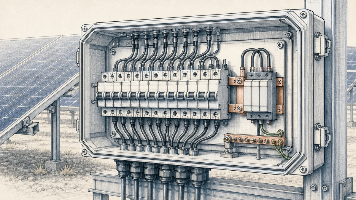
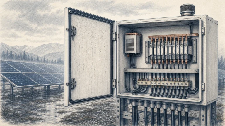
A reliable pv combiner box spd layout is not only about selecting the right DC surge protective device. In a Sinobreaker PV Combiner Box, the physical layout of the SPD, DC conductors, protective bonding path, and service access directly affects surge performance, inspection efficiency, and replacement safety.
IEC 61643-32 describes selection, installation, and coordination principles for PV DC SPDs up to 1,500 V DC, which makes it highly relevant to modern combiner box designs used in utility, commercial, and industrial photovoltaic systems. In practice, the best SPD layout combines three priorities: short connections, low-impedance bonding, and clear replacement access.
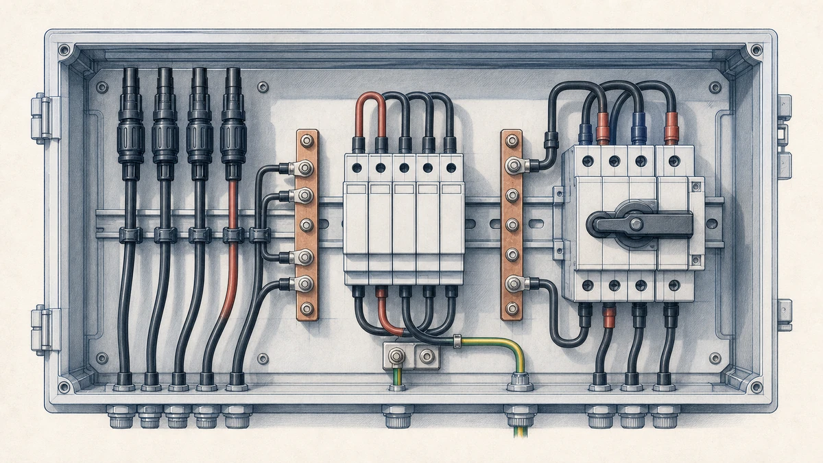
A PV combiner box collects multiple string inputs and routes them toward the inverter or DC distribution system. Because the combiner box is often installed outdoors and connected to long PV string cables, it can be exposed to lightning-induced surges and switching transients.
The DC SPD is intended to divert surge current away from sensitive downstream equipment. However, the SPD can only perform well if its installation path is effective. Long, looped, or poorly bonded SPD conductors add impedance. During a surge, that impedance can increase the residual voltage seen by protected equipment.
For Sinobreaker PV Combiner Box design, the SPD should be treated as a layout-critical component, not as an accessory placed wherever unused panel space remains.
SPD connection conductors should be as short and straight as practical. Schneider Electric notes that added lead length increases the voltage seen at protected equipment during a surge, which is why lead routing matters as much as SPD rating.
In a PV combiner box, this means the SPD should be positioned close to the DC positive and negative bus connection points and close to the protective earth or grounding bar. The layout should avoid unnecessary bends, crossing paths, and long return routes.
Good practice includes:
A short, straight connection path helps reduce let-through voltage and improves the practical effectiveness of the SPD.
The physical loop formed by the positive conductor, negative conductor, SPD, and bonding conductor affects surge behavior. A large loop increases inductance. During a fast transient, this inductance can create additional voltage stress across the protected circuit.
For a Sinobreaker PV Combiner Box, the SPD should be arranged so the DC connection points and PE bonding point are close together. The aim is not only to reduce conductor length, but also to reduce the enclosed loop area.
A compact SPD zone can include:
This arrangement supports both electrical performance and inspection clarity.
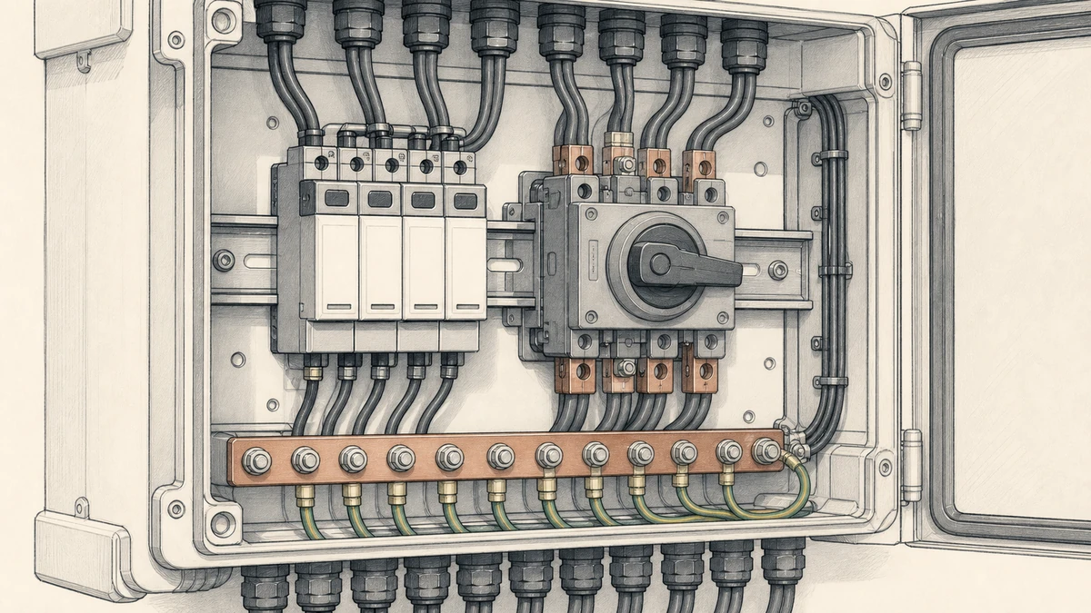
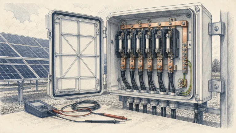
Bonding is central to SPD performance. If the SPD has a weak or indirect connection to earth or the protective bonding network, surge current may not be diverted as intended.
In a metal PV combiner box, bonding should ensure that the enclosure, PE terminal, SPD grounding conductor, cable gland bonding, and external grounding system form a continuous low-impedance path. In non-metallic enclosure designs, the internal PE bar and grounding terminals become even more important because they provide the defined surge current path.
The SPD PE conductor should connect to the main PE bar or grounding terminal with the shortest practical route. The conductor should not be routed through unnecessary terminal chains or shared paths that complicate inspection.
For Sinobreaker PV Combiner Box layouts, the PE path should be:
The goal is to make the protective path obvious to installers, inspectors, and maintenance teams.
IEC 61643-32 covers PV DC SPD selection and installation principles for systems up to 1,500 V DC. For a PV combiner box, the SPD must be suitable for the maximum PV array voltage, system earthing arrangement, and expected surge exposure.
Important selection points include:
Layout cannot compensate for an incorrectly selected SPD. The physical arrangement and the electrical rating must work together.
The best SPD location is usually near the output side of the PV combiner box, close to the DC busbar or main DC isolator, while still maintaining direct access for inspection and replacement. This protects the downstream cable and inverter-side equipment more effectively than a distant SPD position with long internal wiring.
In Sinobreaker PV Combiner Box designs, the SPD location should support three goals:
The SPD should not be hidden behind string fuse holders, cable bundles, monitoring modules, or enclosure structural parts.
Although compact routing is important, the SPD should not be placed in a way that forces technicians to disturb string wiring or output cables during replacement. Serviceability matters because SPDs are sacrificial devices and may need replacement after surge events or end-of-life indication.
A practical layout keeps the SPD near the protected bus while preserving front-facing access to:
This layout reduces service time and lowers the chance of accidental disturbance to live or recently energized PV circuits.
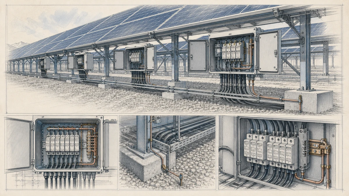
SPD placement affects maintenance. Schneider Electric documentation highlights that visual access and a means to isolate the SPD support replacement and service activity. This is especially important in PV DC applications, where arrays can remain energized whenever light is present.
A Sinobreaker PV Combiner Box should be designed so the maintenance path is clear before the box is installed in the field. If the SPD cannot be seen, isolated, or removed without excessive disassembly, the layout is not service-friendly.
Most PV DC SPDs include a status indicator that shows whether the protective module remains serviceable or has reached end of life. The enclosure layout should allow technicians to see this indicator immediately after opening the door.
Good access design includes:
Clear visual indication shortens inspection time and helps maintenance teams identify replacement needs early.
An SPD may require isolation before replacement, depending on the product design and site procedure. The combiner box should provide a safe and understandable method for disconnecting the SPD from the DC circuit.
Depending on the design, this may involve:
The isolation method should be obvious inside the panel. If a technician must trace unlabeled conductors to understand how the SPD is connected, the layout needs improvement.
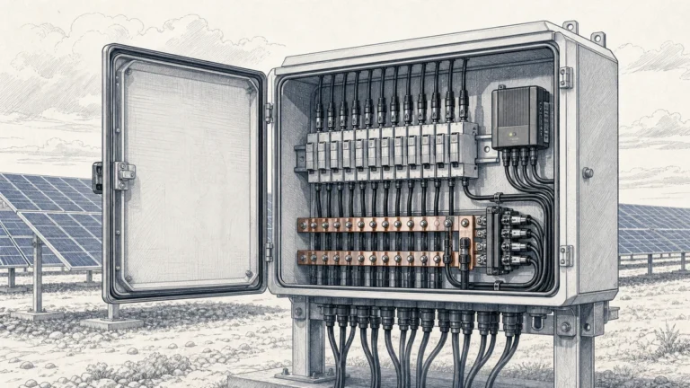
The internal routing of PV combiner box wiring should support both thermal performance and surge performance. DC string conductors, output cables, SPD leads, and PE conductors should be organized so that the SPD path remains direct and visible.
Excess conductor length should not be coiled inside the enclosure. Coiled conductors increase inductance and can reduce the effectiveness of surge diversion. If a supplied SPD lead is too long, it should be trimmed and terminated correctly where permitted by the product instruction and applicable wiring rules.
A clean SPD wiring route uses:
Short conductors should still be serviceable. Do not make the wiring so tight that replacement requires forcing or bending terminals.
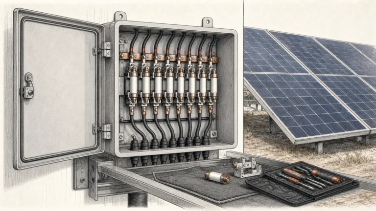
Many DC SPDs use replaceable plug-in modules. The enclosure should provide enough clearance to pull the module straight out without removing nearby equipment. This is a common layout issue in compact combiner boxes.
Design checks should confirm:
Replacement access should be verified during prototype assembly, not only during CAD layout.
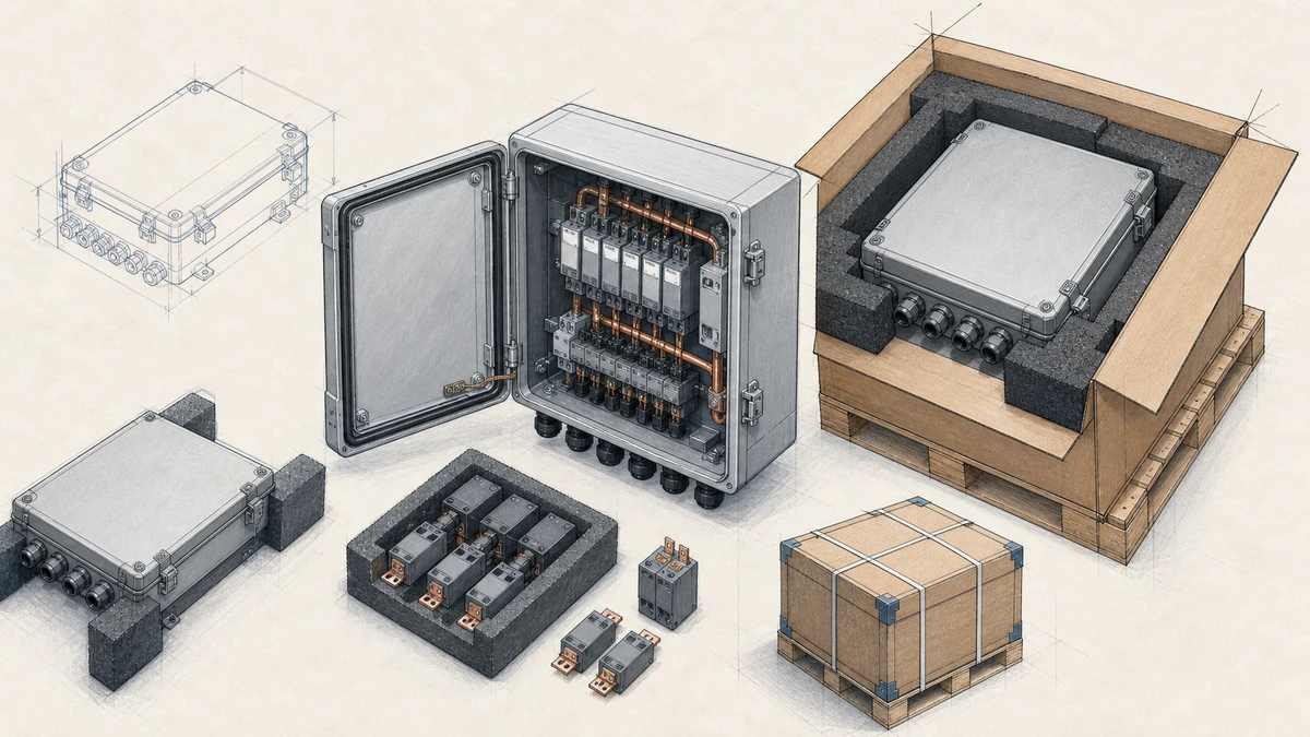
For a practical pv combiner box spd layout, Sinobreaker designs should confirm the following before production:
A good SPD layout is compact but not cramped. It reduces surge path impedance while keeping maintenance safe and predictable.
Lead length matters because surge current changes very quickly. Longer conductors add impedance, and that added impedance can increase the voltage appearing at the protected equipment during a surge. This is why SPD connections in a PV combiner box should be kept as short and straight as practical.
The DC SPD should normally be installed close to the protected DC bus, output terminal area, or DC isolator connection point, with a short connection to the PE bar. It should also remain visible and accessible so technicians can inspect status indicators and replace modules when needed.
Replacement access should allow technicians to see the SPD status indicator, isolate the SPD according to the design, and remove the SPD module without disturbing string wiring, fuse holders, or output cables. Clear labeling, front-facing installation, and adequate hand clearance make maintenance safer and faster.