Adresse
304 North Cardinal
St. Dorchester Center, MA 02124
Heures de travail
Du lundi au vendredi : de 7h00 à 19h00
Le week-end : 10H00 - 17H00
Adresse
304 North Cardinal
St. Dorchester Center, MA 02124
Heures de travail
Du lundi au vendredi : de 7h00 à 19h00
Le week-end : 10H00 - 17H00

PV combiner box schematics serve as the critical communication tool between designers, installers, and inspectors for solar photovoltaic systems. A properly designed single-line diagram not only ensures code compliance but also facilitates troubleshooting and system modifications throughout the installation’s lifespan. Understanding IEEE and IEC schematic standards is essential for creating accurate, professional documentation that meets AHJ requirements.
The schematic design process requires balancing technical accuracy with clarity, using standardized symbols to represent complex electrical components and their interconnections. This guide explores the principles, standards, and best practices for creating comprehensive PV combiner box schematics that satisfy both engineering requirements and regulatory mandates.
Single-line diagrams, also known as one-line diagrams, provide a simplified representation of three-phase or DC electrical systems using single lines to represent conductors and standardized symbols for components. For PV combiner boxes, these diagrams illustrate the path from individual string inputs through protective devices to the combined output feeding the inverter.
The primary purpose of a schematic differs from physical layout drawings. While wiring diagrams show actual conductor routing and terminal connections, schematics focus on the electrical relationships and functional organization of system components. This abstraction allows engineers to analyze circuit behavior without being distracted by physical installation details.
IEEE Standard 315 and IEC 60617 establish the symbolic language for electrical schematics. These standards ensure that any qualified electrician worldwide can interpret your drawings correctly. For PV combiner boxes, critical symbols include fuses, circuit breakers, disconnect switches, surge protection devices, and busbar connections.
💡 Aperçu clé : A well-designed schematic answers three fundamental questions: What components are present? How are they electrically connected? What are their ratings and specifications?
IEEE 315 provides comprehensive guidelines for electrical and electronics diagrams in North America, while IEC 60617 serves as the international standard. For solar installations in the United States, adhering to IEEE conventions ensures compatibility with electrical inspectors’ expectations and industry norms.
The single-line representation simplifies polarity-sensitive DC systems by showing positive and negative conductors as a single line, with polarity indicated by symbols or annotations. This approach reduces drawing complexity while maintaining all essential electrical information. Grounding and bonding connections require special attention, typically shown as separate symbols connecting to the main ground bus.
Component orientation within schematics follows conventional practices: power flows from top to bottom or left to right. PV combiner box schematics typically show string inputs at the top, protective devices in the middle layer, and the combined output at the bottom. This logical flow matches the actual current path and aids in circuit comprehension.
Line weights and styles convey additional information in professional schematics. Main power conductors use heavier lines, while control and monitoring circuits appear as lighter lines. Dashed lines indicate mechanical interlocks or physical groupings, helping readers understand which components reside within the same enclosure.
| Type de composant | IEEE 315 Symbol | IEC 60617 Symbol | Schematic Usage |
|---|---|---|---|
| Fusible | Rectangle with line through center | Rectangle outline | String overcurrent protection |
| Disjoncteur | Switch symbol with rectangular override | Box with diagonal line | Main disconnect and protection |
| SPD (Surge Arrester) | Arrow pointing to ground with gap | Arrow with box symbol | Overvoltage protection |
| Busbar | Heavy horizontal line with connection points | Thick line with junctions | Current consolidation |
| Ground Connection | Three descending parallel lines | Three lines or earth symbol | Equipment grounding |

Professional CAD software like AutoCAD Electrical, EPLAN, or SolidWorks Electrical provides pre-built symbol libraries conforming to IEEE and IEC standards. However, many solar designers use general-purpose drawing tools and must ensure symbol accuracy. Maintaining a verified symbol library prevents inconsistencies across project documentation.
For PV-specific components, some symbols require customization or annotation. The gPV fuse symbol, for instance, appears identical to standard fuse symbols but requires a “gPV” designation to indicate photovoltaic-rated protection. Similarly, DC-rated circuit breakers need voltage and current ratings clearly specified adjacent to the symbol.
Symbol scaling maintains readability across different drawing sizes. A 2-string combiner box schematic on an 8.5×11 sheet requires different symbol sizes than a 12-string utility-scale combiner on a 24×36 drawing. Consistent scaling ratios ensure that all drawings from a single project maintain visual coherence.
Terminal identification on schematic symbols connects the abstract diagram to physical hardware. Using terminal numbers or letters (e.g., L1, L2, N, PE) matching manufacturer documentation facilitates wire tracing during installation and troubleshooting. This cross-reference between schematic and physical reality proves invaluable for field technicians.
⚠️ Important : Always verify that custom or modified symbols comply with applicable standards. Non-standard symbols can lead to misinterpretation, installation errors, and code violations during inspection.
Article 690 du NEC.56(B) mandates that PV systems include diagrams showing the significant components and interconnections. While the code doesn’t explicitly require professional engineering drawings for small systems, professional schematics significantly reduce installation errors and inspection delays. For systems above 250 kW, many jurisdictions require professional engineer certification of electrical documentation.
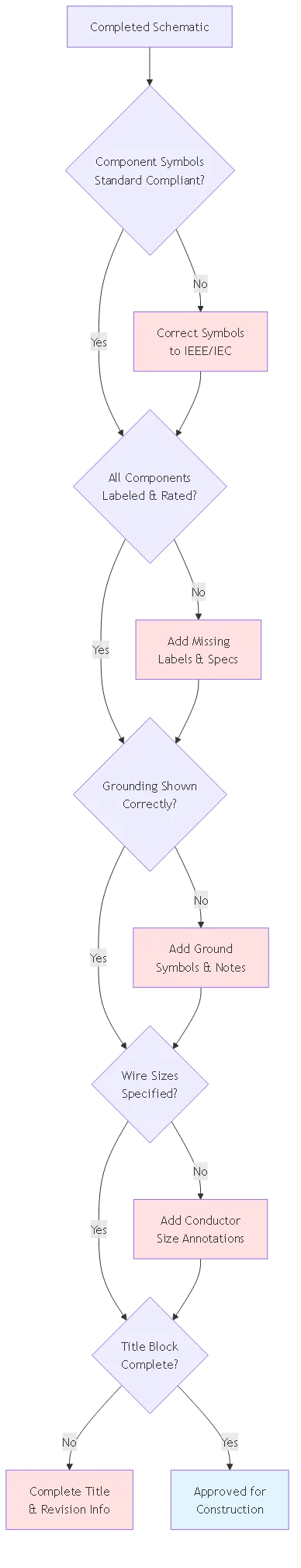
The schematic must capture all information necessary for safe installation and maintenance. This includes conductor sizes, voltage and current ratings, equipment model numbers, and breaker settings. Color-coding or annotation systems help distinguish between different voltage levels, especially in systems combining DC and AC circuits.
Revision control marks another critical aspect of professional documentation. Every schematic should include a revision block showing dates, description of changes, and initials of the engineer responsible. As-built documentation requires updating schematics to reflect field modifications, ensuring that future work proceeds from accurate information.
Electrical schematics integrate with other project documentation including layout drawings, equipment schedules, and wire run lists. Cross-referencing between these documents using consistent nomenclature (e.g., CB-1, F-1A, SPD-1) creates a cohesive documentation package. Many CAD systems support automatic cross-reference generation from schematic data.

A 2-string residential combiner box schematic emphasizes simplicity and clarity. With only two input circuits, the drawing focuses on proper fuse sizing, grounding details, and string monitoring connections if present. Residential systems often include integrated disconnect switches, requiring clear indication of the main service disconnect location.
Commercial 6-string or 8-string combiners introduce complexity through multiple parallel paths. Schematics must clearly show that each string has independent overcurrent protection before combining onto common busbars. Busbar current ratings require calculation and annotation, demonstrating that the combined current of all strings doesn’t exceed busbar capacity.
Utility-scale combiners with 12 or more strings may require multi-sheet schematics or zone-based drawing approaches. One technique divides the schematic into repeating modules: a single detailed 4-string section shown once, with notation indicating “Repeat 3x” to represent a 12-string combiner. This approach maintains drawing clarity while documenting all system components.
Split-bus configurations, where strings feed two separate output circuits, require careful schematic representation. Dashed boundary lines indicate which strings connect to which output buses. This configuration appears in systems with multiple inverters or when implementing maximum power point tracking (MPPT) input optimization.
| String Configuration | Application typique | Schematic Complexity | Key Documentation Focus |
|---|---|---|---|
| 2-String | Residential 3-10 kW | Low – Single sheet | Grounding detail, disconnect location |
| 4-String | Small Commercial 20-50 kW | Medium – Single sheet with detail | Busbar ratings, fuse coordination |
| 8-String | Commercial 100-250 kW | Medium-High – May need zone detail | Parallel conductor grouping, monitoring |
| 12+ String | Utility Scale >500 kW | High – Multi-sheet or modular approach | Sectional isolation, metering integration |
Every component symbol requires unique identification enabling cross-reference to equipment schedules and installation specifications. A systematic naming convention prevents confusion: F1-F4 for fuses, CB-1 for the main breaker, SPD-1 for surge protection. Some designers prefer location-based identifiers like “COMB-A-F1” indicating Combiner Box A, Fuse position 1.
Electrical ratings must appear adjacent to component symbols without cluttering the drawing. A standard format like “15A/1000VDC gPV” provides current rating, voltage rating, and application type in compact form. Conductor sizes typically appear near connection lines, formatted as “10 AWG (2 conductors)” for parallel runs.
Annotation placement follows drafting conventions that prevent overlap with component symbols or connection lines. Horizontal text reading left-to-right proves most readable, even if this requires leader lines connecting annotations to components. Consistent text height throughout the drawing aids readability when documents are printed at various scales.
Special conditions require callout notes explaining exceptions or clarifications. Examples include “Fuse F3 increased to 20A per field modification 2024-08-15” or “SPD connection uses #6 AWG per NEC 690.35(C).” These notes capture engineering decisions that aren’t apparent from the schematic alone.
🎯 Pro Tip : Use a notation key or legend explaining abbreviations and special symbols. This proves especially valuable when designs are reviewed by electrical inspectors unfamiliar with PV-specific terminology.
Proper grounding schematic representation distinguishes between equipment grounding conductors (EGC), grounding electrode conductors (GEC), and bonding connections. IEEE standards use different ground symbols: three descending parallel lines for equipment ground, a single vertical line with horizontal plates for earth ground, and a triangle for chassis ground.
NEC Article 690.41 through 690.47 govern PV system grounding requirements. Schematics must show the grounding electrode system connection, typically indicated with a note referencing the main service grounding point. For ground-mounted arrays, schematics may indicate “To driven ground rod, see site plan” with an arrow pointing to the earth ground symbol.
Array frame bonding appears as connections from the negative busbar or positive busbar (depending on system grounding type) to the equipment ground bus. The schematic should indicate bonding jumper sizes per NEC Table 250.122, even if this information also appears in the equipment schedule. Redundant specification prevents installation errors.
Isolated grounding for monitoring equipment sometimes appears in advanced PV systems. These specialized grounds require clear differentiation from the main equipment ground, often shown as dashed lines or with distinct symbols. Notes must explain the isolation purpose and verify compliance with NEC Article 250 requirements.
DC surge protection devices connect between power conductors and ground, requiring careful schematic representation. Type 1 SPDs appear at the service entrance location, Type 2 at the combiner box output, and Type 3 at individual inverters. Single-line diagrams typically show SPD symbols connected from the busbar to the ground bus with a distinctive surge arrester symbol.
The schematic must indicate SPD voltage ratings (Uc), maximum discharge current (Imax), and voltage protection level (Up). For example: “SPD-1: Type 2, Uc=1000VDC, Imax=40kA, Up=3.5kV” provides complete specification. This information enables installers to verify that installed equipment matches design intent.
SPD disconnector switches appear inline with the SPD connection when required by manufacturer specifications. The schematic shows these as simple switch symbols, often with a note like “SPD disconnect per manufacturer” to clarify their purpose. Some designs use thermal disconnectors that automatically isolate failed SPDs.
Coordination between multiple SPD stages requires indication of their relative locations. When both Type 2 combiner SPDs and Type 3 inverter SPDs exist, the schematic should show sufficient conductor length between them (typically >10 meters) for proper surge current division. Distance notes on connection lines provide this information.
Problème : Mixing IEEE and IEC symbols within a single schematic creates confusion and potential misinterpretation during installation.
Scénarios courants :
– Using IEEE fuse symbols with IEC circuit breaker symbols
– Employing non-standard ground symbols copied from online sources
– Creating custom symbols without explanation or legend
Correction : Select one symbol standard (IEEE 315 for North American projects) and maintain consistency throughout all project drawings. Create a symbol library template preventing inadvertent mixing.
Problème : Schematics showing component symbols without voltage, current, or specification annotations leave critical information undefined.
Scénarios courants :
– Fuse symbols without current ratings
– Circuit breakers without voltage class specification
– SPD symbols without Type designation or Uc rating
Correction : Establish a standard notation format for each component type. Review checklists should verify that every symbol includes minimum required specifications per NEC Article 690.
Problème : Ambiguous ground symbols or missing bonding connections create safety hazards and inspection failures.
Scénarios courants :
– Single ground symbol used for both EGC and earth ground
– Missing equipment bonding jumper representations
– No indication of grounding electrode connection point
Correction : Use distinct IEEE-standard ground symbols for different grounding types. Add notes referencing specific NEC articles governing each ground connection. Show grounding conductor sizes per NEC Table 250.122.
Problème : Schematics without revision tracking lead to installation from outdated drawings and conflicts between field conditions and documentation.
Scénarios courants :
– Field modifications not recorded on as-built drawings
– Multiple drawing versions circulating without version control
– Changes made without date stamps or engineer initials
Correction : Implement formal revision block showing date, description, and responsible engineer for every change. Mark revised areas with clouds or revision triangles. Maintain superseded drawing archive for reference.
AutoCAD Electrical provides industry-standard electrical design tools with extensive symbol libraries and automatic wire numbering. The software generates reports, bills of materials, and wire lists directly from schematic data. Integration with AutoCAD’s 3D modeling enables coordination between electrical and structural designs.
EPLAN Electric P8 offers powerful database-driven design for larger projects. The software maintains relationships between schematics, panel layouts, and equipment lists, automatically updating all documentation when components change. EPLAN’s multi-user environment supports collaborative design for complex installations.
SolidWorks Electrical combines 2D schematic design with 3D cabinet layout in a single environment. Engineers can verify that components fit within enclosures while maintaining electrical correctness. The software’s routing tools suggest optimal wire paths based on schematic connectivity.
Open-source alternatives like QElectroTech provide basic schematic capture for simple projects. While lacking the automation and integration of commercial tools, these programs follow standard symbol conventions and export to common formats. For small residential installations, open-source tools may prove sufficient.
Modern PV combiner boxes often include string monitoring systems measuring current, voltage, and temperature for each input. Schematics must show monitoring sensor connections, typically as dotted lines distinguishing them from power circuits. Current transformers (CTs) appear as circular symbols around conductor lines with polarity marks indicating proper orientation.
Communication wiring for remote monitoring systems requires representation even though it doesn’t affect electrical safety directly. Many designers show communications on separate sheets or in dedicated zones of the schematic. Protocol specifications (Modbus RTU, RS-485, Ethernet) should appear in notes rather than cluttering the main power schematic.
Data acquisition systems integrate with SCADA platforms requiring interface details in project documentation. Schematics may reference separate control diagrams showing the monitoring architecture. At minimum, the combiner schematic should indicate communication terminal blocks with “To SCADA System – See Drawing E-04” type references.
Arc fault detection systems mandated by NEC 690.11 for rooftop systems require sensor representation on schematics. These devices typically connect to the combiner box output and appear as specialized component symbols near the main breaker. Proper placement ensures that arc fault detection covers all DC conductors before the inverter.
Well-designed schematics anticipate future system modifications by showing unused positions in combiner boxes. A 6-string combiner designed for future expansion to 8 strings should show positions 7-8 as “Reserved for Future” with dashed outlines. This documentation prevents field confusion when expansion occurs years after initial installation.
Test point accessibility appears indirectly through schematic organization. Grouping positive and negative test points together, typically at the busbar locations, implies their physical proximity in the actual enclosure. Some designers add small “TP-1” labels indicating dedicated test point terminals.
Fuse replacement procedures benefit from clear schematic organization. Showing all fuse positions with matching F-numbers corresponding to physical enclosure labels enables quick identification during maintenance. Color-coding or position numbers (Top Left, Top Right, etc.) provide additional correlation between drawing and reality.
Expansion joint locations in large utility-scale combiners require documentation when busbars span multiple sections. Schematics use special symbols or notes indicating “Busbar expansion joint – maintain bonding” to alert installers. These details prevent mechanical failures from thermal cycling.
Title blocks capture essential project information including project name, drawing title, scale, date, and sheet number. For PV combiner schematics, the title might read “PV Combiner Box CB-1 Single-Line Diagram” with the project name above. Sheet numbers use formats like “E-3.1” indicating Electrical, Section 3 (PV System), Drawing 1.
Drawing scales typically appear as “NTS” (Not To Scale) for schematics since component spacing doesn’t represent physical dimensions. However, maintaining consistent symbol sizes across drawing sheets creates professional appearance. Some firms establish symbol size standards like “All breaker symbols 0.5 inch height” ensuring uniformity.
Professional engineer stamps and signatures appear in designated areas of title blocks for projects requiring PE certification. Many jurisdictions mandate PE stamps for commercial and utility-scale installations. The stamp area should include license number and jurisdiction of licensure, matching AHJ requirements.
Company logos and standardized borders create professional appearance and brand consistency. Templates incorporating these elements speed drawing creation while ensuring compliance with company standards. Version control numbers in title blocks track drawing evolution throughout project lifecycle.
A schematic (single-line diagram) shows the electrical relationships and component connectivity using standardized symbols, focusing on circuit function rather than physical layout. A wiring diagram shows actual conductor routing, terminal connections, and wire colors matching physical installation. Schematics are used for engineering analysis and code review, while wiring diagrams guide installers during field work. Both documents are typically required for comprehensive project documentation.
IEEE Standard 315 provides the recognized symbolic conventions for electrical and electronics diagrams in North America. This standard ensures compatibility with electrical inspector expectations and industry norms. While IEC 60617 serves international projects, maintaining IEEE consistency throughout North American installations prevents confusion. Some multinational projects may require dual-standard documentation showing both symbol sets.
Every component symbol requires minimum specifications: voltage and current ratings for protective devices, conductor sizes for all power circuits, and SPD classifications with voltage ratings. Include model numbers only when specific equipment is engineered (e.g., “Square D QOU220” versus generic “20A 2P Breaker”). Balance detail with readability—overly cluttered schematics become difficult to interpret. Use equipment schedules for detailed specifications, referencing them from the schematic.
Monitoring system connections can appear on the main schematic using dashed lines to distinguish them from power circuits, or on separate control diagrams. For simple residential systems, showing monitoring on the main schematic provides complete single-sheet documentation. Complex commercial systems benefit from separate monitoring diagrams to prevent schematic clutter. Always include cross-references indicating where monitoring details appear.
Every field modification requires schematic update with revision tracking. Add revision clouds around changed areas, increment the revision number in the title block, and document the change description with date and initials. Maintain superseded drawing archives for reference. Issue revised schematics to all project stakeholders including the AHJ, preventing future work from outdated documentation. NEC Article 690.56(B) mandates maintaining accurate system documentation.
AutoCAD Electrical, EPLAN Electric P8, and SolidWorks Electrical represent professional standards for electrical design. These platforms provide symbol libraries, automatic wire numbering, and integration with other project documentation. For small projects, general CAD programs or even open-source tools like QElectroTech suffice if IEEE symbol standards are maintained. Software selection depends on project complexity, budget, and integration requirements with other design disciplines.
NEC Article 690.56(B) requires diagrams showing “the significant components in the installation.” While the code doesn’t mandate specific drawing standards, schematics must clearly identify all components, their ratings, and interconnections. Inspectors typically expect professional engineering drawings for commercial installations. Include all information necessary for safe installation, operation, and maintenance. Reference relevant NEC articles for grounding, SPD placement, and conductor sizing directly on the schematic.
Ready to create professional-grade PV combiner box schematics for your next solar installation? Contact SYNODE’s technical team for schematic review services and access to our standardized drawing templates meeting IEEE 315 and NEC requirements. Our engineering support ensures your documentation passes inspection on the first submission while establishing clear installation guidance for field teams.
Articles connexes :
- PV Combiner Box Selection: String Count & Current Capacity
- DC Circuit Breaker Specifications for Solar Applications
- Solar Fuse Selection and Coordination Strategies