Adresse
304 North Cardinal
St. Dorchester Center, MA 02124
Heures de travail
Du lundi au vendredi : de 7h00 à 19h00
Le week-end : 10H00 - 17H00
Adresse
304 North Cardinal
St. Dorchester Center, MA 02124
Heures de travail
Du lundi au vendredi : de 7h00 à 19h00
Le week-end : 10H00 - 17H00


Understanding PV combiner box wiring standards ensures code-compliant installations meeting NEC 690.15 requirements while delivering reliable long-term performance. This comprehensive installation guide examines conductor sizing methodology, preparation techniques, terminal connection procedures, grounding and bonding protocols, and verification testing. Electrical contractors and solar installers will find detailed step-by-step procedures, torque specifications, and inspection checklists for professional combiner box wiring installations.
Proper combiner box wiring represents critical installation phase where theoretical design translates to physical implementation. Poor wiring practices—incorrect conductor sizing, inadequate torque, reversed polarity, or missing ground connections—create reliability problems, code violations, and potential safety hazards despite properly specified equipment. Systematic wiring procedures following established standards ensure installations pass inspection first attempt and operate reliably throughout 25-year system lifetime.
NEC 690.15 establishes specific requirements for photovoltaic source circuit and output circuit conductors affecting combiner box wiring design and installation. Understanding these requirements prevents code violations and ensures inspector approval during final review.
Conductor identification requirements:
NEC 690.15(A) mandates photovoltaic source conductors be identified at all points of termination, connection, and where visible. This identification distinguishes PV conductors from other electrical system conductors preventing misidentification during maintenance or emergency response. Acceptable identification methods include:
- Color coding: Use red (or red-striped) for DC positive conductors, white or gray for DC negative grounded conductor (if system uses grounded configuration), black or blue for DC negative ungrounded conductor. NEC permits white conductors for ungrounded negative if permanently re-identified with colored tape, paint, or labels at terminations.
- Permanent labeling: Apply labels at 3-meter (10-foot) maximum intervals and at all termination points identifying conductors as “PV positive,” “PV negative,” or equivalent terminology. Use UV-resistant outdoor-rated labels for exposed installations preventing fading and deterioration.
- Physical separation: Route PV DC conductors in dedicated raceways separate from AC conductors per NEC 690.31(C) providing inherent identification through separate routing systems.
Multiconductor cable requirements:
When using multiconductor cable assemblies (Type USE-2, PV Wire, or similar) for combiner connections, NEC 690.31(B) permits single cable containing both positive and negative conductors. Cable jacket must be sunlight-resistant and rated for wet locations (outdoor installations) or appropriate for conduit enclosure. Individual conductors within cable must maintain proper identification through color coding or labeling at terminations where conductors become visible.
NEC 110.26 establishes working space requirements for electrical equipment applicable to combiner box installations. While often overlooked during installation, working space violations create code compliance issues and safety hazards during maintenance operations.
Minimum working space dimensions:
- Width: Minimum 762mm (30 inches) or width of equipment, whichever is greater
- Depth: Minimum 914mm (36 inches) for equipment operating 151-600V to ground
- Height: Minimum 2.0 meters (6.5 feet) or height of equipment, whichever is greater
- Access: Clear access to working space with no obstructions
Document working space dimensions on installation drawings ensuring inspector can verify compliance during plan review. Rooftop combiner installations must maintain working space despite roof penetrations, HVAC equipment, or other obstructions potentially encroaching on required clearances.
Accessibility requirements per NEC 690.15(C):
Combiner boxes must locate in readily accessible locations permitting inspection, maintenance, and replacement without requiring extensive dismantling of building structure or electrical systems. “Readily accessible” means capable of being reached quickly without requiring ladders, keys, or removal of obstacles. This requirement affects combiner mounting location selection ensuring long-term serviceability.
Rooftop locations generally satisfy accessibility requirements if accessible via permanent roof access (hatch, stairs, or fixed ladder). Interior attic locations require adequate lighting and clear access pathway meeting building code egress requirements. Avoid locations requiring extensive equipment removal or specialized access equipment for routine maintenance.
| NEC Requirement | Spécifications | Common Violations | Inspection Focus |
|---|---|---|---|
| 690.15(A) Conductor ID | Color coding + labels every 3m | Missing labels, faded markings | Visual conductor inspection |
| 690.8(B) Ampacity | 156% of Isc with derating | Undersized, missing derating | Calculation verification |
| 110.26 Working Space | 762mm × 914mm × 2.0m clear | Obstructions, insufficient depth | Physical measurement |
| 690.43 Equipment Ground | Continuous, sized per 250.122 | Splices, wrong size, poor termination | Continuity testing |
💡 Aperçu clé : NEC 690.15 requirements extend beyond simple conductor connection encompassing identification, sizing, routing, and accessibility. Comprehensive understanding of these requirements prevents common installation mistakes causing inspection failures. Maintain NEC 2023 copy on job sites enabling field verification of specific requirements during installation.
Accurate conductor measurement and clean cutting establish foundation for quality combiner wiring. Errors at this preparatory stage compound through installation creating difficult-to-correct problems.
Conductor length calculation:
Calculate required conductor length accounting for actual installation routing plus service loops and termination allowances. Typical calculation: Physical distance + bends (add 150mm per 90° bend) + service loops (300mm each end) + termination allowance (200mm each end) = total required length.
Example: String combiner to inverter = 25-meter straight-line distance with two 90° bends, service loops at combiner and inverter, terminal connections both ends:
– Base distance: 25,000mm
– Bend allowance: 2 × 150mm = 300mm
– Service loops: 2 × 300mm = 600mm
– Termination: 2 × 200mm = 400mm
- Total length: 26,300mm (26.3 meters)
Cut conductors using appropriate tools for conductor type: cable cutters for solid conductors, ratcheting cutters for stranded conductors up to 2/0 AWG, hydraulic cutters for larger sizes. Avoid hack saws or diagonal cutters creating ragged cut ends requiring extensive cleanup. Clean cut ends allow proper terminal crimping and prevent strand fraying during installation.
Proper insulation removal exposes correct conductor length for terminal connection without damaging conductor strands or leaving excessive exposed metal creating shock hazards.
Strip length determination:
Terminal manufacturer specifications define required strip length matching terminal barrel depth. Common strip lengths:
- Compression lugs: 10-15mm strip length with conductor fully inserted to barrel backstop
- Bornes à ressort: 10-12mm strip exposing conductor for spring mechanism capture
- Screw terminals: 8-10mm forming hook wrapping around screw shaft
Measure strip length from conductor end using ruler or terminal block measurement markings. Mark insulation at appropriate distance using marker or thumbnail impression providing visual reference during stripping.
Stripping technique:
Use automatic wire strippers adjusted for conductor gauge ensuring clean insulation removal without nicking strands. Hold stripper perpendicular to conductor applying gentle pressure while rotating tool through stripping motion. Inspect stripped conductor for damage:
- Acceptable: Clean copper with all strands intact, smooth insulation edge
- Unacceptable: Nicked strands, ragged insulation edge, excessive strip length
Damaged conductors require re-stripping at different location or conductor replacement if damage cannot eliminate. Never use conductors with nicked or broken strands creating weak points prone to failure under current load or mechanical stress.
Compression terminal lugs create gas-tight mechanical connection between conductor and combiner terminals preventing oxidation and maintaining stable contact resistance over decades. Proper crimping technique ensures reliable connections.
Lug selection criteria:
Match terminal lug to conductor size and combiner terminal configuration:
- Conductor size: Lug must accommodate conductor gauge without forcing
- Barrel type: Standard barrel (solid conductors), long barrel (fine-strand flexible)
- Tongue type: Ring (bolted connections), spade (some terminal blocks), pin (spring-clamp)
- Matériau: Copper lugs for copper conductors (dissimilar metals cause galvanic corrosion)
- Plating: Tin-plated prevents oxidation, recommended for all outdoor/high-humidity applications
Crimping procedure:
1. Select appropriate crimping die matching lug size and manufacturer specifications
2. Insert stripped conductor fully into lug barrel until insulation contacts barrel entry
3. Verify conductor strands fill barrel without excess strands protruding from barrel end
4. Position lug in crimping tool with die properly aligned to barrel (follow manufacturer orientation marks)
5. Apply full crimping pressure using ratcheting tool until tool releases (indicating proper crimp compression)
6. Inspect crimped connection verifying proper barrel deformation and conductor retention
7. Perform pull test applying 45N (10 pounds) force—properly crimped lug resists conductor pullout
Mark crimped terminals with permanent marker indicating installation date and technician initials creating quality control documentation. Store pre-crimped conductors carefully preventing terminal damage before final installation.
Systematic terminal block organization simplifies installation and troubleshooting providing logical connection sequence matching system documentation.
Standard wiring arrangement:
Most combiner boxes organize terminals in sequential order: String 1 positive, String 1 negative, String 2 positive, String 2 negative, etc. This arrangement groups each string pair together simplifying conductor routing and circuit tracing. Verify combiner terminal layout matches expected organization before beginning wiring:
- Sequential pairs: S1+, S1−, S2+, S2−, S3+, S3− (grouped by string)
- Separate poles: S1+, S2+, S3+, S4+ | S1−, S2−, S3−, S4− (grouped by polarity)
Combiner documentation should clearly identify terminal arrangement through internal schematic labels. When documentation unclear, trace internal busbar connections determining actual terminal organization before connecting field wiring.
Color coding implementation:
Apply consistent color coding throughout installation preventing wiring errors:
- Positive DC: Red conductors or white conductors with red tape/labels at all visible points
- Negative DC (grounded): White or gray conductors (if system uses grounded DC)
- Negative DC (ungrounded): Black or blue conductors
- Equipment ground: Green, green/yellow stripe, or bare copper
Label each conductor at terminal block connection plus 300mm back from terminal using durable labels (Brady, Dymo embossed) reading: “String 1 Positive,” “String 2 Negative,” etc. Labeling both at terminal and along conductor enables circuit tracing during troubleshooting without requiring terminal disassembly.
Proper terminal torque creates reliable electrical connection without damaging terminal hardware or crimped lugs. Under-torqued connections create high contact resistance causing heating and premature failure. Over-torqued connections crush lug barrels, crack terminal blocks, or strip screw threads.
Manufacturer torque specifications:
Combiner documentation provides terminal torque specifications typically organized by terminal type:
- M3 screws: 0.5-0.6 N⋅m (4-5 lb⋅in)
- M3.5 screws: 0.8-1.0 N⋅m (7-9 lb⋅in)
- M4 screws: 1.2-1.5 N⋅m (11-13 lb⋅in)
- M5 screws: 2.5-3.0 N⋅m (22-27 lb⋅in)
- M6 screws: 4.0-6.0 N⋅m (35-53 lb⋅in)
- M8 screws: 8-12 N⋅m (71-106 lb⋅in)
Use calibrated torque screwdriver or torque wrench appropriate for specified range. Torque tools must show current calibration certificate (annual calibration typical) ensuring accuracy. Never estimate torque by “feel”—even experienced electricians cannot consistently achieve proper torque without calibrated tools.
Torquing procedure:
1. Insert lug tongue into terminal with lug body fully seated against terminal face
2. Thread screw hand-tight ensuring proper screw engagement in threads
3. Select appropriate driver bit (hex, Torx, Phillips) matching screw drive type
4. Set torque tool to specified value per manufacturer documentation
5. Position tool perpendicular to terminal applying steady pressure while rotating
6. Continue rotation until torque tool clicks or breaks over indicating proper torque achieved
7. Mark torqued connection using paint pen or torque stripe across screw head and adjacent surface
8. Document torque completion on installation checklist or QC form
Torque marks provide visual indication of proper initial torque allowing future inspection to detect loosened connections through broken or misaligned marks. Some installations require torque re-verification after 30 days accounting for thermal cycling and connection settling—initial torque marks document original torque enabling comparison with verification torque.
Polarity errors represent common wiring mistake potentially causing protection device malfunction, monitoring errors, or equipment damage. Systematic polarity verification prevents these errors through multiple independent checks.
Visual verification:
Trace positive conductors (red) from string terminals to combiner positive busbar confirming continuity. Trace negative conductors (black, blue, white, or gray) to negative busbar. Look for crossed conductors, reversed terminal connections, or color code errors. Visual verification catches obvious errors but may miss subtle problems in complex wiring bundles—supplement with electrical testing.
Voltage testing:
With modules uncovered (or using artificial light), measure voltage between string terminals verifying expected polarity:
1. Set multimeter to DC voltage range (select range exceeding expected Voc, typically 1000V)
2. Touch black (negative) meter probe to conductor marked “String 1 Negative”
3. Touch red (positive) meter probe to conductor marked “String 1 Positive”
4. Verify meter shows positive voltage reading (if meter shows negative voltage, polarity is reversed)
5. Repeat for all strings verifying consistent polarity across all circuits
Continuity verification:
With system de-energized, use ohmmeter measuring resistance from string positive terminals through combiner internal wiring to output positive terminal. Very low resistance (< 1Ω) confirms correct connection path. Repeat for negative circuit. High or infinite resistance indicates open circuit, wrong polarity connection, or internal combiner wiring problem.
Document polarity verification results on commissioning checklist including technician signature and date. Polarity problems discovered after system energization require shutdown, correction, and re-testing creating costly delays—proactive pre-energization verification prevents these issues.
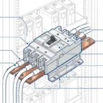
Combiner output terminals connect to main busbar through bolted, compression, or spring-clamp interfaces depending on combiner design. Proper busbar connection ensures low-resistance current path handling combined string output.
Bolted busbar connections:
Premium combiners use direct busbar bolting with output lugs attaching directly to exposed busbar sections:
1. Position crimped lug against busbar with lug hole aligned to busbar mounting hole
2. Insert stainless steel bolt (M6 or M8 typical) through lug and busbar
3. Add split lock washer plus flat washer on bolt back side
4. Thread nut onto bolt hand-tightening until components snug together
5. Hold nut stationary using wrench while torquing bolt head to specification
6. Apply torque in two stages: 50% of specification, verify alignment, then 100% final torque
7. Mark completed connection with torque stripe across nut, washer, and adjacent surface
Compression terminal connections:
Standard combiners use heavy-duty compression terminals accepting large-gauge output conductors:
1. Strip output conductor to length specified by terminal manufacturer (typically 15-20mm)
2. Insert stripped conductor fully into terminal barrel until insulation contacts barrel entry
3. Position compression die properly aligned to barrel orientation marks
4. Apply full crimping pressure until ratcheting tool releases
5. Insert crimped terminal into combiner output terminal block
6. Torque terminal screw per manufacturer specification
7. Mark and document completed connection
Spring-clamp terminals:
Some commercial combiners use high-current spring-clamp terminals simplifying installation:
1. Prepare conductor with appropriate strip length (typically 12-15mm for high-current terminals)
2. Activate terminal release mechanism (button, lever, or screwdriver-actuated)
3. Insert stripped conductor fully until it contacts internal backstop
4. Release terminal mechanism allowing spring to capture conductor
5. Perform pull test applying 90N (20 pounds) force verifying secure retention
6. Measure exposed conductor confirming no bare metal visible outside terminal housing
Document output connection details including conductor size, torque values (for torqued terminals), and visual inspection results confirming proper installation.
Proper output conductor routing from combiner to inverter maintains circuit integrity, satisfies code requirements, and provides professional installation appearance.
Conduit installation standards:
Output circuit conductors typically route in metallic (EMT, rigid) or non-metallic (Schedule 40 PVC, HDPE) conduit depending on installation environment:
- Exposed outdoor: Rigid metal conduit or Schedule 80 PVC for mechanical protection and UV resistance
- Rooftop concealed: EMT or Schedule 40 PVC with proper supports every 1.4 meters
- Underground: Schedule 40 PVC, HDPE, or metallic in concrete-encased duct bank per NEC 300.5
- Interior building: EMT typical for commercial installations, NM cable permitted residential (if suitable for PV application)
Conductor pulling techniques:
Long conduit runs require proper pulling techniques preventing conductor damage:
1. Apply pulling lubricant (non-conductive, wire-pulling specific) to conductors at conduit entry
2. Use pulling eye or kellum grip attaching to conductor ends (never pull on conductor insulation)
3. Maintain straight pulling angle avoiding sideways force binding conductors in conduit
4. Limit pulling tension to 300N (67 pounds) for copper conductors preventing conductor elongation
5. For difficult pulls, install pull points (junction boxes) every 30 meters reducing total pull length
6. Support conductors at pull completion preventing conductor weight from stressing terminations
Maintain service loops (300-450mm) at combiner and inverter allowing future terminal maintenance without conductor tension. Coil excess conductor neatly securing with cable ties avoiding tangled bundles blocking enclosure access.
Comprehensive conductor labeling satisfies NEC requirements while simplifying future troubleshooting and maintenance.
Required label locations per NEC 690.15(A):
– At conductor origin (combiner output terminals)
– At conductor termination (inverter input terminals)
– Every 3 meters (10 feet) along exposed conductor routes
– At all access points (junction boxes, pull boxes, conduit entries)
Label content specifications:
Effective labels communicate circuit function, voltage, and warnings:
- Circuit identification: “PV Combiner Output,” “Positive DC from Combiner A”
- Voltage information: “600V DC,” “Maximum Voc: 520V”
- Polarity: “Positive (+),” “Negative (−)”
- Warnings: “PHOTOVOLTAIC POWER SOURCE,” “DO NOT DISCONNECT UNDER LOAD”
Use UV-resistant outdoor-rated labels (vinyl, polyester) for exposed installations. Indoor installations may use paper labels if protected from moisture. Apply labels to clean, dry conductor jackets ensuring good adhesion. Wrap clear tape over labels in high-traffic areas preventing accidental label removal.
Proper equipment grounding provides fault current return path protecting personnel and equipment during ground fault conditions. NEC 690.43 establishes specific grounding requirements for PV systems.
EGC sizing per NEC 250.122:
Size equipment grounding conductor based on overcurrent protection device rating protecting circuit:
– 15A or 20A overcurrent protection: #14 AWG copper minimum (#12 AWG copper with 20A aluminum/copper-clad aluminum conductors)
– 30A protection: #10 AWG copper
– 40A protection: #10 AWG copper
– 60A protection: #10 AWG copper
– 100A protection: #8 AWG copper
PV installations often specify oversized EGC (one or two sizes larger than minimum) improving surge protection effectiveness by reducing ground impedance. For example, use #10 AWG even when #12 AWG satisfies code minimum.
EGC routing requirements:
Route EGC with circuit conductors in same raceway maintaining parallel path minimizing inductance. Never route EGC separately from associated circuit conductors creating ground loops and increasing impedance. NEC 250.134(B) requires EGC to be:
– Continuous without splices (preferred)
– If splicing necessary, use listed splice connectors with compression or exothermic weld (no wire nuts)
– Protected from physical damage
– Securely fastened to prevent displacement
Termination procedures:
Terminate EGC at combiner equipment ground terminal using compression lug ensuring gas-tight connection:
1. Strip EGC insulation 15mm exposing conductor for lug barrel insertion
2. Install compression lug using appropriately sized crimping die
3. Connect lug to combiner ground terminal using stainless steel hardware
4. Torque connection per manufacturer specifications
5. Continue EGC to inverter and system grounding electrode maintaining continuous path
Test ground continuity measuring resistance from combiner enclosure through EGC to grounding electrode. Target < 1Ω confirms adequate low-impedance ground path. Resistance > 2Ω indicates poor connections, undersized conductor, or missing bonding jumpers requiring investigation and correction.
Photovoltaic module frames require bonding to equipment grounding system per NEC 690.43(B) ensuring all exposed conductive surfaces remain at same electrical potential during fault conditions.
Bonding methods:
- Listed module bonding devices: Specialized clamps or washers installed at module mounting locations creating electrical connection between module frame and mounting rail
- Bonding jumpers: Flexible conductors (typically #8 or #6 AWG bare copper) connecting module frames to mounting structure
- Continuous bonding: Listed rail systems providing continuous conductive path through entire array requiring only periodic bonding to EGC
Install bonding connections at clean metal surfaces removing paint, anodizing, or oxidation ensuring good electrical contact. Use stainless steel or approved bimetallic hardware preventing galvanic corrosion between dissimilar metals (aluminum frames, steel rails).
Array-to-combiner bonding:
Connect array frame bonding system to combiner equipment ground creating integrated grounding system:
1. Run bonding conductor from array mounting structure to combiner location
2. Size bonding conductor per NEC 250.122 (same as or larger than EGC)
3. Terminate bonding conductor at combiner enclosure ground terminal or busbar
4. Maintain electrical continuity through all connections avoiding reliance on mechanical pressure alone
Document bonding installation through photographs showing bonding connections, hardware details, and termination locations. Testing bonding integrity using low-resistance ohmmeter confirming < 0.1Ω between array frame and combiner ground validates proper installation.
Comprehensive pre-energization testing identifies wiring errors and installation deficiencies correctable before system energization avoiding troubleshooting under full system voltage.
Continuity testing:
Measure DC resistance through each circuit path verifying proper connections:
1. String circuits: Measure resistance from string terminals at array through combiner to output terminals. Target < 1Ω confirms good connections and appropriate conductor sizing.
2. Output circuit: Measure resistance from combiner output to inverter input terminals. Calculate acceptable resistance from conductor properties: R = ρ × L / A (where ρ = resistivity, L = length, A = cross-section). For 6 AWG copper, 50 meters: R ≈ 0.65Ω maximum.
3. Ground circuit: Measure resistance from combiner enclosure to system grounding electrode. Target < 1Ω confirms adequate ground path.
Resistances significantly exceeding calculated values indicate poor connections, incorrect conductor size, or broken conductors requiring investigation and repair before proceeding.
Insulation resistance testing:
Verify adequate insulation between conductors and from conductors to ground prevents ground faults and ensures personnel safety:
1. Use megohmmeter rated for test voltage exceeding system operating voltage (typically 500V or 1000V test voltage for PV systems)
2. Disconnect array from combiner (open fuses/breakers or physically disconnect conductors)
3. Measure insulation resistance:
– Positive busbar to ground
– Negative busbar to ground
– Positive busbar to negative busbar
4. Target reading: > 1MΩ (higher is better, > 10MΩ indicates excellent insulation)
Readings < 500kΩ suggest moisture intrusion, damaged insulation, or contamination requiring cleaning or conductor replacement. Document all insulation resistance measurements creating baseline data for future comparison detecting degradation trends.
Polarity verification:
Final polarity check before energization prevents costly errors:
1. With modules still covered, verify zero voltage at all combiner terminals
2. Uncover one string confirming voltage appears at correct combiner terminals
3. Measure voltage with multimeter verifying positive indication when red probe contacts positive terminal, black probe contacts negative terminal
4. Repeat for all strings confirming consistent polarity
5. Measure output voltage confirming polarity matches input polarity
6. Document verification results with technician signature
Systematic energization procedure manages risks during initial system startup:
Sequential energization:
1. Initial conditions: Verify all modules covered, combiner fuses/breakers open, inverter disconnected
2. First string energization:
– Uncover String 1 modules
– Measure open-circuit voltage at combiner String 1 terminals
– Close String 1 fuse/breaker
– Verify voltage appears at combiner output
– Monitor combiner temperature (should remain near ambient)
3. Second string energization:
– Uncover String 2 modules
– Measure String 2 voltage
– Close String 2 fuse/breaker
– Verify combined voltage at output (should equal individual string voltage, not double)
– Measure output current under load conditions confirming additive string currents
4. Inverter connection:
– Connect inverter DC input
– Enable inverter allowing MPPT startup
– Verify inverter successfully tracks power and begins AC output
– Monitor system for 15-30 minutes confirming stable operation
Vérification des performances :
Measure key electrical parameters documenting baseline performance:
- String voltages: Record each string Voc confirming expected values ±5%
- String currents: Measure each string current under full sun (>800 W/m²) confirming balanced output ±10%
- Output voltage: Verify matches individual string voltage
- Output current: Confirm equals sum of string currents ±5%
- Combiner temperature: Measure internal temperature confirming < ambient +20°C
Document all measurements, photographs of completed installation, and any anomalies requiring monitoring or future attention. Provide commissioning report to system owner including electrical test data, as-built documentation, and maintenance recommendations.
Size conductors per NEC 690.8(B) requiring 156% of circuit short-circuit current with temperature derating. For string inputs with 12A Isc: minimum capacity = 12A × 1.56 = 18.72A. Apply rooftop temperature derating (0.58 typical for 60°C ambient, 75°C conductor) requiring 32A conductor capacity suggesting 10 AWG copper. Output conductors carry combined current: For two strings, 24A × 1.56 = 37.4A requiring 6 AWG copper after derating.
Equipment grounding conductor sizes per NEC 250.122 based on overcurrent device rating: #12 AWG minimum for 20A protection, though #10 AWG or larger recommended for improved surge protection. Request manufacturer conductor recommendations verifying against NEC calculations ensuring compliant sizing. Oversized conductors minimize voltage drop improving system efficiency—calculate actual voltage drop ensuring < 2% from array to inverter.
Torque terminal connections per manufacturer specifications using calibrated torque tools. Typical specifications: M3 = 0.5-0.6 N⋅m, M4 = 1.2-1.5 N⋅m, M5 = 2.5-3.0 N⋅m, M6 = 4-6 N⋅m, M8 = 8-12 N⋅m. Never estimate torque by feel—use calibrated torque screwdriver or torque wrench with current calibration certificate ensuring accuracy.
Under-torqued connections create high resistance causing heating and premature failure. Over-torqued connections damage terminals, strip threads, or crush compression lugs. Mark torqued connections with paint stripe across screw head and adjacent surface providing visual indication of proper initial torque. Some installations require torque re-verification after 30 days accounting for thermal cycling and connection settling. Document all torque values and verification dates on commissioning checklist.
No—NEC 110.14(B) requires conductor splicing methods suitable for application conditions. Wire nuts (twist-on connectors) lack weatherproofing and compression force appropriate for outdoor PV applications experiencing temperature extremes, vibration, and long-term reliability requirements. PV systems demand compression splices, exothermic welds, or listed splice blocks rated for outdoor use and DC operation.
Combiner box internal connections use compression terminals or screw terminals designed for direct conductor termination without separate splicing. String input and output circuits require continuous conductors from array to combiner to inverter avoiding unnecessary splices introducing failure points. When splices prove unavoidable (conductor length limitations, circuit modifications), use listed compression splices with properly sized dies creating gas-tight mechanical connection. Document all splice locations and methods on as-built drawings enabling future troubleshooting.
NEC 690.15(A) mandates conductor identification at all termination points and visible locations. Required labels include: Circuit identification (“String 1 Positive,” “Combiner Output”), voltage information (“600V DC Maximum”), polarity indicators (“+,” “−”), and warnings (“PHOTOVOLTAIC POWER SOURCE”). Apply labels every 3 meters along exposed conductors, at junction boxes, and at termination points.
Use UV-resistant outdoor-rated labels (vinyl, polyester) for exposed installations preventing fading. Label both at terminal connections and 300mm back along conductors enabling circuit tracing without terminal disassembly. Additional recommended labels include installation date, contractor information, and torque completion marks. NEC 690.56 also requires arc-flash hazard labels on equipment doors warning personnel about shock and arc-flash risks. Comprehensive labeling satisfies code requirements while improving long-term maintainability.
Verify polarity through visual inspection plus electrical testing. Visual verification: Trace positive conductors (red) from string terminals to combiner positive busbar confirming continuity. Trace negative conductors to negative busbar. Electrical verification with modules uncovered: Set multimeter to DC voltage range, touch black probe to negative conductor, red probe to positive conductor. Positive meter reading confirms correct polarity; negative reading indicates reversal requiring correction.
Perform polarity checks for each string individually plus output circuit. Document results on commissioning checklist with technician signature. Never energize system without polarity verification—reversed polarity may cause protection device malfunction, monitoring errors, or equipment damage requiring expensive repairs. Additional verification: Measure voltage between positive and negative at multiple points along circuit confirming consistent polarity throughout installation.
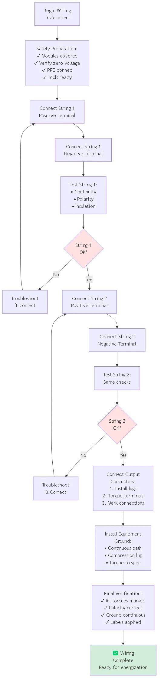
Wire one complete string at a time: connect String 1 positive, connect String 1 negative, perform continuity and polarity testing, then proceed to String 2. This sequential approach enables immediate verification of each string before moving to next preventing compounding errors difficult to troubleshoot in fully-wired combiner.
Complete string inputs before wiring output circuit. After all string connections verified, install output conductors connecting combiner to inverter. Install equipment grounding conductor as final wiring step ensuring all enclosure components bonded to ground. Systematic sequence prevents mistakes, enables progressive testing, and creates logical documentation flow matching installation photos to wiring diagrams. Mark each completed connection preventing accidental double connections or missed terminations.
Implement quarterly visual inspection checking for signs of overheating (discoloration, melted insulation), loose connections (torque marks misaligned), or physical damage. Quarterly inspection takes 10-15 minutes verifying status indicators, enclosure integrity, and visible connection condition. Annual comprehensive inspection includes terminal torque verification, insulation resistance testing, and thermal imaging of all connections under load.
After major thunderstorms or weather events, perform special inspection checking for lightning damage, water intrusion, or storm-related problems. Some jurisdictions require periodic professional inspection (3-5 year intervals) by licensed electrician documenting system condition for insurance or code compliance. Proactive inspection identifies developing problems enabling preventive maintenance rather than reactive emergency repairs. Document all inspections with photographs and test data creating historical record supporting warranty claims and tracking degradation trends.
Professional PV combiner box wiring requires systematic approach following NEC 690.15 requirements and industry best practices. Understanding conductor sizing methodology, preparation techniques, torque specifications, grounding procedures, and verification testing ensures code-compliant installations passing inspection first attempt while delivering reliable long-term performance.
Principaux enseignements :
1. NEC 690.15 mandates conductor identification, proper sizing (156% of Isc), working space clearances, and accessibility for all combiner installations
2. Conductor preparation demands accurate measurement, clean cutting, proper strip lengths, and compression terminal installation using calibrated crimping tools
3. Terminal torque specifications require calibrated tools—typical values range 0.5-12 N⋅m depending on screw size with torque marks documenting completion
4. Equipment grounding follows NEC 250.122 sizing with continuous EGC maintaining < 1Ω resistance to system grounding electrode 5. Pre-energization testing including continuity, insulation resistance (>1MΩ target), and polarity verification prevents costly post-energization troubleshooting
Proper wiring installation directly determines system reliability, safety, and longevity. Investment in quality installation practices—proper tools, systematic procedures, thorough testing—pays dividends through first-time inspection approval, reliable operation, and reduced maintenance requirements over 25-year system lifetime.
Ressources connexes :
- PV Combiner Box Selection: Sizing and Specifications
- What is a Combiner Box? Component Functions Explained
- DC SPD Installation: Surge Protection Integration
Ready for professional combiner box wiring installations? Contact our technical training department for hands-on installation workshops, NEC compliance seminars, and field installation support ensuring your team delivers quality photovoltaic combiner installations meeting code requirements and industry standards.
Dernière mise à jour : Décembre 2025
Auteur : L'équipe technique de SYNODE
Révisé par : Field Installation Services Department