Adresse
304 North Cardinal
St. Dorchester Center, MA 02124
Heures de travail
Du lundi au vendredi : de 7h00 à 19h00
Le week-end : 10H00 - 17H00
Adresse
304 North Cardinal
St. Dorchester Center, MA 02124
Heures de travail
Du lundi au vendredi : de 7h00 à 19h00
Le week-end : 10H00 - 17H00


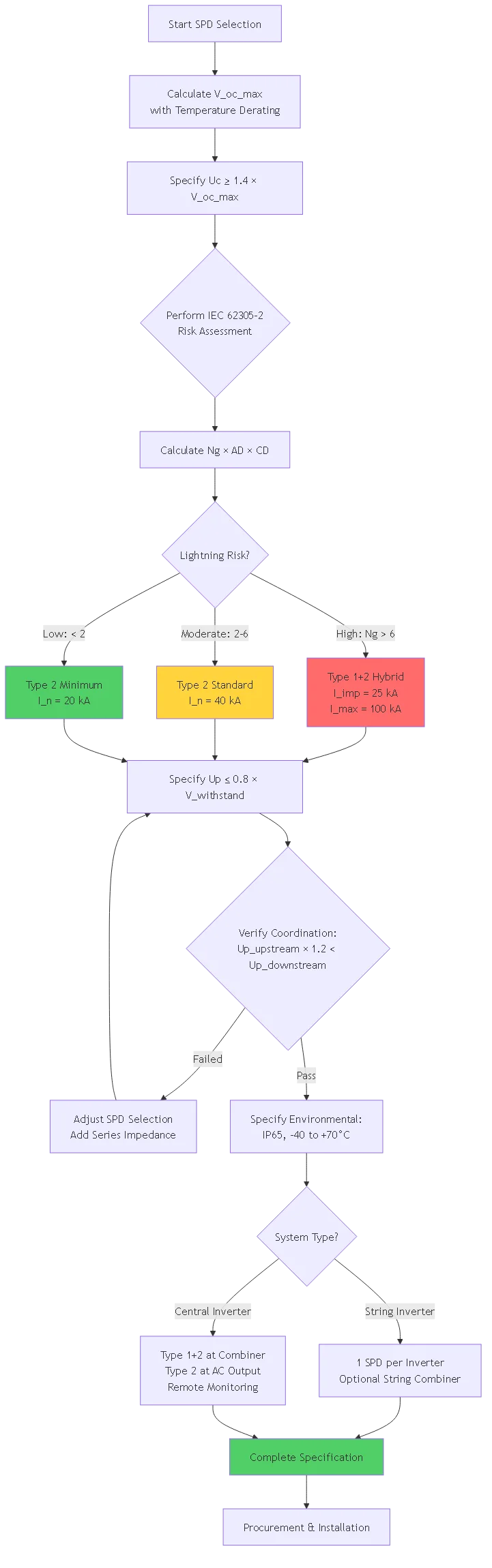
PV lightning protection engineering applies the zone protection concept—a systematic approach that divides installations into distinct lightning protection zones (LPZ), each with progressively lower electromagnetic interference and surge stress.
Traditional lightning protection focuses on preventing direct strikes using structural systems. Zone protection recognizes that electromagnetic effects extend far beyond strike points, requiring coordinated protection at zone boundaries where lightning current, electromagnetic fields, and conducted surges transition between different severity levels.
This guide explains the engineering principles underlying zone-based protection design for photovoltaic installations. You’ll learn how to define lightning protection zones according to IEC 62305-4 standards, calculate electromagnetic threat levels at zone boundaries, design coordinated surge protection systems that manage energy as it transitions between zones, and optimize protection investments by matching device specifications to actual threat characteristics.
💡 Key Insight: Zone protection isn’t about installing the highest-rated surge protectors everywhere—it’s about understanding how lightning threats diminish as you move from external exposure (LPZ 0) through structural protection (LPZ 1) to equipment locations (LPZ 2 and beyond), then specifying appropriate protection at each transition point.
The zone protection concept divides any installation into distinct volumes with different electromagnetic threat characteristics. Each zone boundary represents a protection interface where surge energy must be managed.
LPZ 0A – Direct Lightning Exposure (External Unprotected)
This is the external environment outside any lightning protection structure. Objects in LPZ 0A face direct lightning strike risk plus full electromagnetic field exposure.
Threat characteristics:
– Direct lightning current: 200kA (IEC 62305 Level I)
– Peak electromagnetic field: H = 200kA/m (at 1m distance)
– Voltage induced in loops: V = μ₀ × A × (dH/dt) = potentially millions of volts
– Surge current waveform: 10/350μs (direct strike energy content)
For PV systems: Solar panels, mounting structures, and exposed DC wiring in LPZ 0A require structural lightning protection (air terminals, down conductors) to intercept strikes before reaching equipment. Ground-mounted arrays without structural LPS remain in LPZ 0A indefinitely.
LPZ 0B – Indirect Lightning Exposure (External Protected)
External environment protected by structural lightning protection system but still exposed to electromagnetic fields from nearby strikes.
Threat characteristics:
– No direct strike current (protected by air terminals)
– Reduced electromagnetic field: H = 20-50kA/m (shielded by LPS conductors)
– Conducted surges via utility lines: 25-50kA (8/20μs waveform)
– Induced voltages in cable loops: 1,000-10,000V
For PV systems: Rooftop arrays on buildings with lightning protection, or ground-mount arrays with air terminal systems operate in LPZ 0B. DC cables entering buildings transition from LPZ 0B to LPZ 1 at building entry point.
LPZ 1 – Building Interior (First Protected Zone)
Volume inside building structure or shielded enclosure. Lightning current divided among multiple down conductors and building structural steel.
Threat characteristics:
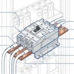
– Direct lightning current reduced to <50kA per conductor (divided among multiple paths) – Electromagnetic field: H = 5-15kA/m (attenuated by building structure) – Conducted surges: 10-25kA (8/20μs waveform entering via cables) – Equipotential bonding reduces voltage differences to <2,500V For PV systems: Building-mounted inverters, combiner boxes inside enclosures, and main distribution equipment operate in LPZ 1. This is the typical location for Type 1 or Type 2 SPDs managing energy transitioning from external cables.
LPZ 2 and Beyond – Equipment Protection Zones (Enhanced Protected)
Volumes inside metal enclosures, shielded rooms, or behind secondary protection devices with further electromagnetic attenuation and surge suppression.
Threat characteristics:
– No direct lightning current (stopped at LPZ 0→1 boundary)
– Electromagnetic field: H = 0.5-5kA/m (multiple shielding layers)
– Residual surges: 1-5kA after primary SPD operation
– Voltage limited to <1,500V by coordinated SPD cascade For PV systems: Sensitive inverter electronics, monitoring equipment, control circuits, and communication devices operate in LPZ 2+. Type 2 and Type 3 SPDs at equipment terminals manage residual energy passing through LPZ 1 protection.
Protection effectiveness depends on proper management at zone boundaries, not just device installation within zones.
Three Transition Rules:
1. All conductive elements crossing zone boundaries require bonding or surge protection: Cables, pipes, structural steel, cable shields—anything conductive creates a potential surge pathway.
2. Protection device ratings must match source zone characteristics: SPDs at LPZ 0→1 boundary need Type 1 ratings (10/350μs, 100kA), while LPZ 1→2 transitions use Type 2 (8/20μs, 40kA).
3. Multiple zone boundaries provide cascaded energy reduction: Each properly implemented transition reduces surge energy by 60-90%, allowing final equipment protection with lower-rated, less expensive devices.
🎯 Conseil de pro: Think of zone protection like pressure reduction in plumbing systems. You don’t install a single high-capacity pressure regulator—you use multiple stages (city main → building entry → equipment connection) with progressively finer regulation. Lightning protection works identically with cascaded energy management.
Proper zone-based protection requires quantifying actual threat levels at each boundary, not simply assuming maximum values everywhere.
Lightning creates time-varying magnetic fields that induce voltages in cable loops. Field strength determines induced voltage magnitude.
Basic Field Equation:
H = I / (2π × r)
Où ?
– H = magnetic field strength (A/m)
– I = lightning current (A)
– r = distance from current path (m)
Example Calculation – LPZ 0A to LPZ 0B Transition:
Ground-mount PV system with air terminals. Down conductor carries 100kA lightning current at 5m distance from DC cable run.
H = 100,000A / (2π × 5m) = 3,183 A/m = 3.18 kA/m
Induced Voltage in Cable Loop:
V_induced = μ₀ × A × (dH/dt)
Où ?
- μ₀ = 4π × 10-⁷ H/m (perméabilité de l'espace libre)
– A = loop area (m²)
– dH/dt = field change rate (A/m/s)
For 10m × 0.5m cable loop (A = 5m²) with 10/350μs waveform:
– dH/dt ≈ 3,183 A/m / 10μs = 3.18 × 10⁸ A/m/s
V_induced = 4π × 10⁻⁷ × 5 × 3.18 × 10⁸ = 2,000V
Protection requirement: SPD at building entry must clamp voltages >2,000V, requiring Type 1 device with voltage protection level Up ≤ 2.5kV.
When lightning strikes a structure with multiple down conductors, current divides among paths. Calculate partial current in each path to determine SPD requirements.
Current Division Formula:
I_partial = I_total × (1/n) × k_c
Où ?
– I_total = total lightning current (kA)
– n = number of down conductors
– k_c = configuration factor (0.5-1.0 depending on geometry)
Example – Commercial Rooftop PV System:
Building with 4 down conductors equally spaced around perimeter. Lightning strikes one corner.
I_total = 100kA (IEC 62305 Level III)
n = 4 conductors
k_c = 0.7 (corner strike, not equally divided)
I_partial = 100kA × (1/4) × 0.7 = 17.5kA per conductor
However, cables entering building near strike point may carry additional current through capacitive and inductive coupling. Safety factor 2.0× applied:
I_design = 17.5kA × 2.0 = 35kA
Protection requirement: Type 1 SPD at building entry must handle 50kA minimum (next standard rating above 35kA calculated requirement).
Different surge waveforms carry different energy content. Match SPD energy handling capacity to actual threat.
Energy in Surge (Simplified):
W = ∫ V(t) × I(t) dt
For practical SPD selection, use specific energy metric:
Specific Energy = (I² × t) / R
Comparing waveforms:
– 10/350μs (Type 1): W_specific = 10,000 kA²μs (high energy, direct strike)
– 8/20μs (Type 2): W_specific = 160 kA²μs (medium energy, conducted surge)
– 1.2/50μs-8/20μs (Type 3): W_specific = 12 kA²μs (low energy, residual surge)
Zone boundary energy reduction:
LPZ 0→1 transition: 10,000 kA²μs → 160 kA²μs (98.4% reduction with Type 1 SPD)
LPZ 1→2 transition: 160 kA²μs → 12 kA²μs (92.5% reduction with Type 2 SPD)
This progressive energy reduction allows final LPZ 2→3 protection using low-cost Type 3 devices instead of expensive high-energy SPDs throughout.
Effective zone protection requires SPD coordination ensuring proper energy sharing and voltage clamping at each transition.
When multiple SPDs protect a circuit, improper coordination causes one device to fail while others remain inactive. Coordination ensures appropriate energy sharing.
Coordination Methods:
Method 1 – Distance Coordination (Decoupling)
Minimum cable length between SPD types provides inductive decoupling that ensures upstream device activates first.
Required minimum distances:
– Type 1 to Type 2: 10 meters minimum
– Type 2 to Type 3: 5 meters minimum
– Same type SPDs: 15 meters minimum
Impedance calculation:
Z_cable = √(R² + (ωL)²)
For DC cable at surge frequencies (100kHz):
– L ≈ 1μH/m
– R ≈ 0.01Ω/m (neglected at high frequency)
– Z ≈ 2πf × L = 0.63Ω/m
10m cable: Z = 6.3Ω
This impedance causes voltage drop during surge events, ensuring upstream Type 1 SPD conducts before downstream Type 2 reaches its clamping voltage.
Method 2 – Impedance Coordination (Series Elements)
When insufficient distance available, add series impedance (inductor or resistor) between SPD types.
Inductor sizing:
L_series = (U_p2 – U_p1) / (di/dt)
Où ?
– U_p1 = upstream SPD voltage protection level
– U_p2 = downstream SPD voltage protection level
– di/dt = current rise rate
Exemple :
– Type 1 SPD: U_p = 4.0kV
– Type 2 SPD: U_p = 2.5kV
– Surge: di/dt = 10kA/μs
L_series = (4,000V – 2,500V) / (10 × 10⁹ A/s) = 150μH
Install 150-200μH inductor between Type 1 and Type 2 SPDs when separation <10m.
Method 3 – Manufacturer-Coordinated Sets
Use pre-tested SPD combinations from single manufacturer with documented coordination testing.
Avantages :
– No calculation required
– Guaranteed energy sharing per test results
– Often allows closer spacing than calculated minimum
– Insurance/code compliance documentation included
Example coordinated set:
Dehn DEHNguard T1+T2 system:
– Type 1 module: 100kA Iimp (10/350μs)
– Type 2 module: 40kA In (8/20μs)
– Minimum separation: 5m (vs. 10m for uncoordinated)
– Tested energy sharing: 70% upstream, 30% downstream
SPDs must be coordinated not just for current sharing but also voltage clamping to prevent equipment exposure to excessive voltage.
Voltage Coordination Rule:
U_p(downstream) < 0.8 × U_equipment
And:
U_p(upstream) × k_lead < U_p(downstream)
Où ?
– U_p = SPD voltage protection level
– U_equipment = equipment surge withstand voltage
– k_lead = lead length factor (1.0 + 0.5V/m)
Example System:
Inverter surge immunity: 6kV
Type 1 SPD: U_p = 4.0kV, installed with 0.5m leads
Type 2 SPD: U_p = 2.5kV, installed with 0.3m leads
Check downstream SPD rating:
2.5kV < 0.8 × 6kV = 4.8kV ✓ (adequate protection) Check voltage with lead inductance:
Type 1 voltage at 10m distance with 10kA surge:
V_total = 4.0kV + (0.5m × 1μH/m × 10kA/μs) = 4.0kV + 5kV = 9kV ✗ (exceeds inverter rating)
Solution: Reduce Type 1 lead length to <0.2m, or increase separation to allow Type 2 to clamp before voltage reaches inverter.
Proper SPD placement at zone boundaries maximizes protection effectiveness and minimizes installation cost.
Placement Strategy by Zone Transition:
LPZ 0→1 Transitions (Type 1 SPDs):
– Array combiner boxes (ground-mount systems)
– Building entry junction boxes (rooftop systems)
– Service entrance panels (AC side)
– Maximum 1 per 100-150kW of array capacity
LPZ 1→2 Transitions (Type 2 SPDs):
– Inverter DC input terminals
– Inverter AC output terminals
– Sub-distribution panels
– Every equipment connection point
LPZ 2→3 Transitions (Type 3 SPDs):
– Communication port connections
– Control circuit terminals
– Monitoring equipment inputs
– Sensitive electronics only
Installation density calculation:
Number of SPD locations = (Critical equipment count) + (Zone boundary crossings)
For 100kW system:
– 1 Type 1 location (combiner box)
– 4 Type 2 locations (2 inverters × 2 sides)
– 6 Type 3 locations (inverter comms + monitoring)
– Total: 11 SPD installation points
Map installation identifying distinct electromagnetic threat volumes.
Zone Definition Criteria:
Physical boundaries:
– Building walls (LPZ 0→1 transition)
– Metal enclosures (LPZ 1→2 transition)
– Shielded cables/conduits (within-zone field reduction)
Electromagnetic boundaries:
– Structural LPS coverage (LPZ 0A→0B transition)
– Cable entry points (conductive path crossing zones)
– Equipotential bonding bars (voltage equalization within zone)
Example System Zoning:
50kW commercial rooftop installation:
LPZ 0A: Roof surface where array mounts (no building lightning protection)
LPZ 1: Building interior (structural steel provides some field attenuation)
– DC cables from roof to inverter room
– Inverter room equipment
LPZ 2: Inside inverter enclosure
– Inverter DC input circuitry
– Inverter AC output circuitry
– Control boards
LPZ 3: Shielded control circuits
– Communication boards
– Monitoring equipment
– Internet connection
Quantify electromagnetic stress at each zone transition using methods from previous section.
Boundary Threat Assessment Matrix:
| Zone Boundary | Current Threat (kA) | Field Strength (kA/m) | Induced Voltage (kV) | Required SPD |
|---|---|---|---|---|
| LPZ 0A→1 | 100-200 | 50-200 | 5-15 | Type 1, 100kA |
| LPZ 0B→1 | 25-50 | 10-50 | 2-8 | Type 1, 50kA |
| LPZ 1→2 | 10-25 | 5-15 | 1-3 | Type 2, 40kA |
| LPZ 2→3 | 1-5 | 0.5-5 | 0.5-1.5 | Type 3, 5kA |
Select SPD types, ratings, and quantities based on calculated threats.
SPD Specification Matrix:
For each zone boundary, specify:
1. SPD type (1, 2, or 3)
2. Discharge current rating (In or Iimp)
3. Voltage protection level (Up)
4. MCOV rating (for DC circuits)
5. Quantity and location
Example Specification – LPZ 0B→1 Boundary:
Location: Rooftop combiner box
Cables: 3 DC strings, 600V nominal, 750V Voc
Threat: 50kA conducted surge from utility or nearby strike
SPD Specification:
– Type: Type 1 (handles lightning current from external zone)
– Rating: Iimp = 50kA (10/350μs), In = 100kA (8/20μs)
– Voltage: Up = 3.5kV, MCOV = 1000V (>750V × 1.15 = 862V requirement)
– Configuration: 2-pole (positive + negative), plus ground
– Quantity: 1 device protecting all 3 strings at common bus
– Coordination: Minimum 12m cable to inverter Type 2 SPDs
Ensure protection cascades properly without unwanted interactions.
Coordination Verification Checklist:
– [ ] Minimum separation distances met (Type 1→2: 10m, Type 2→3: 5m)
– [ ] Voltage protection levels coordinated: Up(upstream) > Up(downstream)
– [ ] Energy capability decreases toward equipment: W(T1) > W(T2) > W(T3)
– [ ] MCOV ratings appropriate for each circuit (>1.15× Voc or Vnom)
– [ ] No parallel SPD paths that bypass protection cascade
– [ ] Ground connections to common bonding point (star configuration)
– [ ] Lead lengths minimized at all SPD locations (<1m total)
Mathematical Verification:
Check voltage at equipment after cascade operation:
V_equipment = U_p(final) + Σ(Z_cable × I_surge) + Σ(V_lead × L_lead × di/dt)
Must satisfy: V_equipment < U_withstand(equipment)
Complete engineering documentation for installation, inspection, and code compliance.
Required Documentation:
Protection zone drawings:
– Site plan with zone boundaries marked
– Building sections showing zone transitions
– SPD locations identified on single-line diagrams
Calculation sheets:
– Electromagnetic field calculations at boundaries
– Partial lightning current distribution
– SPD coordination verification
– Voltage protection level cascade analysis
Equipment specifications:
– Complete SPD datasheets with test reports
– Installation instructions from manufacturers
– Coordination test results for SPD combinations
Compliance certification:
– IEC 62305-4 conformance statement
– Lightning protection system design certification
– As-built deviations from design (if any)

Zone effectiveness depends not just on SPD placement but also on how cables transition between zones.
Cable Shielding Requirements by Zone:
LPZ 0 → LPZ 1 transitions:
– Use fully shielded cables or metallic conduit for all conductors
– Ground cable shield at both ends to bonding bars
– Maintain shield continuity across connectors
– Shield effectiveness target: 40dB attenuation at 100kHz
LPZ 1 → LPZ 2 transitions:
– Shielded twisted-pair construction minimum
– Ground shield at equipment end only (avoid ground loops)
– Use feedthrough filters on power lines if available
– Shield effectiveness target: 20dB attenuation
LPZ 2 → LPZ 3 transitions:
– Foil shielding plus drain wire acceptable
– Separate signal and power cable routing
– Use shielded enclosures for sensitive equipment
– Shield effectiveness target: 10dB attenuation
Cable Routing Rules:
Minimize loop areas to reduce induced voltages:
Maximum loop area calculation:
A_max = V_allow / (μ₀ × dH/dt)
For 1kV allowable induced voltage:
A_max = 1000V / (4π × 10⁻⁷ × 10⁸ A/m/s) = 79.6 m²
Equivalent to: 10m run with 8m separation—achievable with proper routing.
Practical implementation:
– Run positive and negative DC cables in close proximity or twisted together
– Use cable trays with metal covers (provides shielding)
– Route cables along building structural steel when possible
– Cross zone boundaries perpendicular to minimize exposure length
Effective zone protection requires eliminating voltage differences between conductive elements within the same zone.
Bonding Resistance Requirements:
Maximum resistance between bonded elements:
R_bond < V_allow / I_max
For LPZ 1 with 10kA partial lightning current and 500V allowable difference:
R_bond < 500V / 10,000A = 0.05Ω = 50 milliohms
Achieving low-resistance bonding:
Method 1 – Compression Bonding:
Use listed compression lugs torqued to specifications
– Copper-to-copper: Achieve 10-20 milliohms
– Copper-to-aluminum: Use bimetallic lugs + anti-oxidant compound, achieve 30-50 milliohms
– Large surface area: 25mm² minimum contact area per standard
Method 2 – Exothermic Welding:
Permanently bond conductors using Cadweld or similar process
– Achieves <5 milliohms per connection – Requires specialized equipment and training – Preferred for buried connections and critical grounding Method 3 – Bonding Bars:
Central copper busbar (6mm × 25mm minimum) with star-point topology
– All bonding conductors terminate at single bar
– Bar connected to grounding electrode with large conductor (50-95mm²)
– Achieves 5-15 milliohms from any point to ground reference
Testing bonding resistance:
Use 4-wire resistance meter (Kelvin method) to verify low-resistance connections:
1. Connect current terminals across bond
2. Connect voltage terminals on either side of bond
3. Inject 10A test current
4. Measure voltage drop (should be <0.5V for 50 milliohm bond)
Zone protection allows targeted investment at critical boundaries rather than equal protection everywhere.
Protection Cost Structure:
| Protection Level | SPD Configuration | Cost per Location | Typical System Coût |
|---|---|---|---|
| LPZ 0→1 (Type 1) | 100kA Iimp DC or AC rated | $500-$1,200 | $1,000-$3,000 (1-3 locations) |
| LPZ 1→2 (Type 2) | 40kA In DC + AC sides | $200-$600 | $800-$2,400 (4-6 locations) |
| LPZ 2→3 (Type 3) | 5kA combined Data/comm lines | $50-$200 | $300-$1,200 (6-12 locations) |
| Total System | Complete coordination | - | $2,100-$6,600 installed |
Cost Reduction Through Zone Strategy:
Non-optimized approach: Install Type 1 SPDs at every protection point
– 12 locations × $800 = $9,600
Zone-optimized approach: Match SPD type to actual threat level
– 2 Type 1 locations: 2 × $800 = $1,600
– 4 Type 2 locations: 4 × $400 = $1,600
– 6 Type 3 locations: 6 × $100 = $600
– Total: $3,800 (60% cost reduction with equal or better protection)
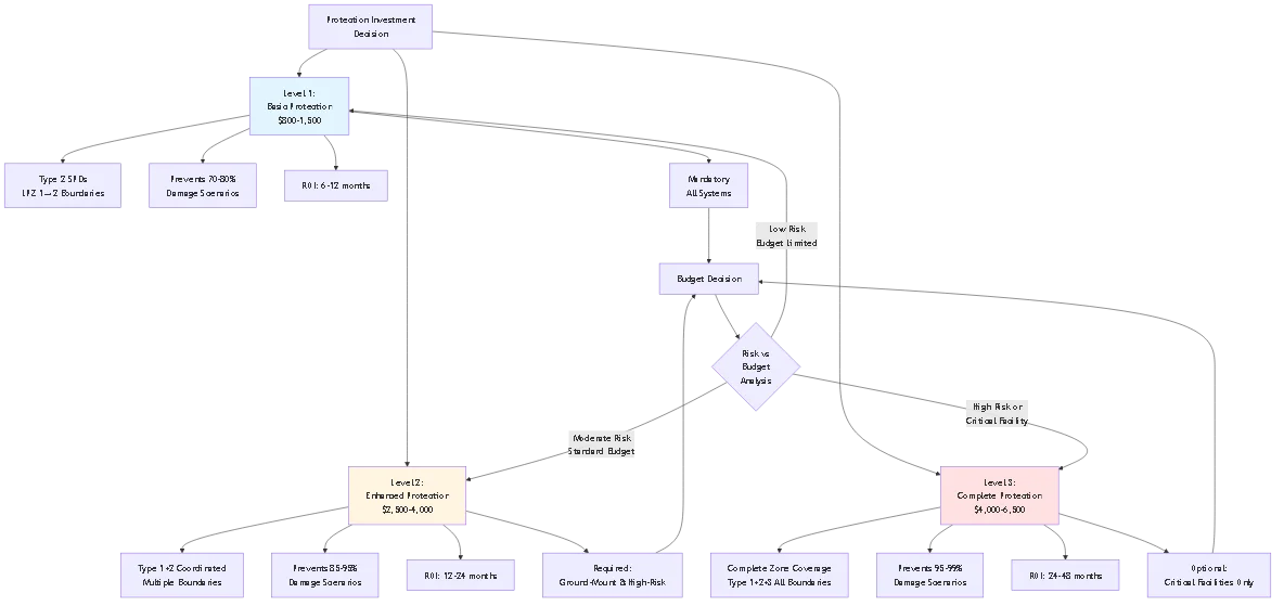
Each additional protection level provides diminishing returns. Optimize investment by focusing on high-value boundaries.
Protection Effectiveness vs. Cost:
Level 1: Basic Type 2 Protection ($800-$1,500)
– Prevents 70-80% of likely damage
– ROI: 6-12 months
– Recommendation: Mandatory for all systems
Level 2: Enhanced Type 1+2 Coordination ($2,500-$4,000)
– Prevents additional 15-20% of damage
– ROI: 12-24 months
– Recommendation: Required for ground-mount and high-risk systems
Level 3: Complete Zone Protection with Type 3 ($4,000-$6,500)
– Prevents additional 3-7% of damage
– ROI: 24-48 months
– Recommendation: Optional except for critical facilities
Optimization Strategy:
Invest protection budget at boundaries with highest damage probability:
1. Priority 1: LPZ 1→2 transitions (inverter DC/AC connections) – $800-$1,500
2. Priority 2: LPZ 0→1 transitions if ground-mount or high-risk – $1,000-$2,500
3. Priority 3: LPZ 2→3 transitions for sensitive monitoring – $300-$600
System characteristics:
– Suburban location, Ng = 15 (moderate lightning)
– Building has no lightning protection
– Single string inverter in garage
– 24 panels on south-facing roof
Zone Definition:
- LPZ 0A: Roof surface with panels
- LPZ 1: Garage interior (building walls provide minimal shielding)
- LPZ 2: Inside inverter enclosure
No LPZ 3 defined (monitoring via WiFi, adequate in LPZ 2)
Threat Assessment:
LPZ 0A→1: Conducted surge via DC cables, estimated 15kA maximum
LPZ 1→2: Residual surge after cable impedance, estimated 5kA
Protection Specification:
LPZ 0A→1 boundary: Not protected (cost optimization for low-risk residential)
LPZ 1→2 boundary:
– Type 2 DC SPD at inverter: 40kA In, Up = 2.5kV, MCOV = 1000V ($250)
– Type 2 AC SPD at inverter: 40kA In, Up = 1.5kV ($200)
Total protection cost: $450 + $200 installation = $650
Design rationale: Skips expensive Type 1 SPDs (would add $800-$1,200) since rooftop location with building shielding reduces direct strike risk to <2%. Type 2 protection prevents 85% of likely damage scenarios for 40% of comprehensive protection cost.
System characteristics:
– Rural location, Ng = 28 (high lightning)
– Open field, array is tallest structure
– 4 string inverters in equipment shelter
– Comprehensive monitoring system
Zone Definition:
- LPZ 0A: Array mounting structure (exposed, no LPS)
- LPZ 0B: After structural LPS protection (air terminals added)
- LPZ 1: Equipment shelter interior
- LPZ 2: Inside inverter enclosures
- LPZ 3: Monitoring equipment rack
Threat Assessment:
LPZ 0A→0B: Direct strike potential, 100kA maximum via structural LPS
LPZ 0B→1: Conducted surge via DC cables after air terminal protection, 50kA
LPZ 1→2: Residual after Type 1 SPD and cable impedance, 10kA
LPZ 2→3: Final residual surge to monitoring, 2kA
Protection Specification:
Structural Protection (LPZ 0A→0B):
– 6 air terminals on 3m poles around array perimeter
– Copper down conductors to ground rod array
– Ground resistance achieved: 6.8Ω
– Cost: $8,500
LPZ 0B→1 boundary (combiner boxes):
– 2× Type 1 SPDs: 100kA Iimp, Up = 4.0kV, MCOV = 1200V ($1,600)
LPZ 1→2 boundary (inverters):
– 4× Type 2 DC SPDs: 65kA In, Up = 2.5kV ($1,200)
– 4× Type 2 AC SPDs: 65kA In, Up = 1.5kV ($1,200)
LPZ 2→3 boundary (monitoring):
– 8× Type 3 data line SPDs: 5kA combined wave ($400)
Total protection cost: $13,900
Design rationale: Ground-mount requires full zone protection due to direct strike exposure. Structural LPS provides LPZ 0A→0B transition, allowing lower-rated (less expensive) Type 1 SPDs at building entry compared to unprotected array scenario requiring higher ratings.
Lightning protection zones (LPZ) are distinct spatial volumes with progressively lower electromagnetic threat levels, defined by IEC 62305-4 standards for systematic protection design. Zones matter because lightning damage mechanisms vary by location—external equipment faces direct strike risks plus intense electromagnetic fields, while interior equipment primarily experiences conducted surges through cables, requiring different protection approaches.
The zone concept allows engineers to match protection device specifications to actual threat levels rather than over-protecting low-risk areas or under-protecting exposed locations. LPZ 0 (external environment) requires high-energy Type 1 surge protectors handling direct lightning current with 10/350μs waveforms, while LPZ 2 (inside shielded enclosures) needs only Type 2 or Type 3 devices managing residual surges with 8/20μs waveforms. This targeted approach reduces total protection costs by 40-60% compared to installing maximum-rated devices everywhere while improving reliability through proper energy coordination. Modern PV systems typically implement 3-4 protection zones: external array exposure (LPZ 0), building interior with combiner boxes (LPZ 1), inverter enclosures (LPZ 2), and sensitive monitoring circuits (LPZ 3). Each zone boundary requires appropriate surge protection matched to electromagnetic stress transitioning between zones. Understanding zones helps system designers specify cost-effective protection that addresses actual threats.
Electromagnetic field calculation at zone boundaries uses the magnetic field equation H = I / (2π × r) where H is field strength in amperes per meter, I is lightning current in amperes, and r is distance in meters from the current path to the evaluation point. This calculation determines induced voltages in cable loops crossing zone boundaries, which directly impacts SPD voltage rating requirements.
For practical PV system design, assume lightning current of 100kA for moderate protection (IEC 62305 Level III) or 200kA for high protection (Level I). Measure distance from nearest down conductor or structural steel carrying lightning current to DC cable runs entering the building—this is your r value. Calculate field strength then determine induced voltage using V = μ₀ × A × (dH/dt) where A is loop area formed by outgoing and return conductors. For example, DC cables 5 meters from a down conductor carrying 100kA create H = 100,000A / (2π × 5m) = 3,183 A/m field strength. A 10m cable run with 0.5m spacing (5m² loop) experiences induced voltage V = 4π×10⁻⁷ × 5m² × (3183 A/m / 10μs) = 2,000V. This calculation shows you need SPD with voltage protection level below 2,000V at that boundary. The magnetic field approach is more accurate than simple voltage assumptions because it accounts for actual installation geometry and current division among multiple conductive paths.
Minimum separation between Type 1 and Type 2 SPDs is 10 meters of cable length for inductive decoupling that ensures proper energy coordination without requiring additional impedance elements. This distance provides sufficient cable inductance (approximately 10μH) to create voltage drop during surge events that forces the upstream Type 1 device to conduct before the downstream Type 2 reaches its lower clamping voltage.
The 10-meter rule comes from coordination testing showing that closer spacing can cause the Type 2 SPD to conduct first despite being downstream, potentially exceeding its energy capacity while the Type 1 remains inactive—exactly the opposite of intended cascade protection. If your installation cannot achieve 10-meter physical separation due to space constraints, three alternatives exist: install series inductance of 15-20μH between SPD types to substitute for missing cable inductance, use manufacturer-coordinated SPD sets specifically tested for closer spacing (typically allowing 5-7 meters with documented compatibility), or employ combined Type 1+2 devices in single housings that include internal coordination circuitry. The separation requirement applies to cable carrying surge current between SPDs—routing can include bends and elevation changes as long as total conductor length meets the minimum. For Type 2 to Type 3 coordination, minimum separation reduces to 5 meters since lower energy levels require less decoupling impedance. Always maintain specified minimums regardless of visual appearance—proper coordination determines whether protection functions or fails during actual lightning events.
Type 1 SPDs can typically be omitted from residential rooftop solar systems under 15kW located on buildings in urban or suburban areas where the array is not the highest point and the building lacks structural lightning protection, provided you install Type 2 SPDs at the inverter. This cost-optimization strategy recognizes that rooftop arrays benefit from surrounding building shielding and operate in what IEC 62305 classifies as LPZ 0B (indirect exposure) rather than LPZ 0A (direct exposure), reducing maximum surge threat from 100-200kA direct strike levels to 15-30kA conducted surge levels.
However, Type 1 protection becomes mandatory for: any ground-mounted system regardless of size (these are preferential strike points), rooftop systems that extend significantly above the roof peak (becoming the highest point), installations in high lightning-risk areas where building code requires comprehensive protection (Ng >30 strikes/km²/year), and systems where insurance or warranty specifically requires IEC 62305-compliant protection with documented Type 1 SPD installation. The economic analysis supports skipping Type 1 in low-risk rooftop scenarios—adding Type 1 SPDs costs $800-$1,500 additional but prevents only 5-10% more damage scenarios beyond what Type 2 protection alone prevents, yielding poor ROI for typical residential installations. Commercial systems generally should include Type 1 protection due to higher equipment values, business interruption costs, and insurance requirements. When uncertain, consult with a lightning protection specialist who can perform site-specific risk assessment considering local lightning density, building geometry, and surrounding structures.
SPD replacement frequency varies by zone and exposure level because devices in external zones (closer to lightning threat sources) experience more frequent surge events and higher energy stress than interior devices. Type 1 SPDs at LPZ 0→1 boundaries typically require replacement every 8-12 years in moderate lightning areas or after any known direct strike within 500 meters, Type 2 SPDs at LPZ 1→2 boundaries last 10-15 years with occasional replacements after significant surge events, and Type 3 SPDs at LPZ 2→3 boundaries may function 15-20 years unless exposed to equipment faults or switching transients.
However, calendar-based replacement is less critical than condition-based monitoring. Modern SPDs include end-of-life indicators—LED lights or mechanical flags—showing operational status continuously. Check these monthly for Type 1 and Type 2 devices (30-second visual inspection), semi-annually for Type 3 devices. Green or OK indication means device is functional; red or REPLACE indication requires immediate replacement regardless of age—failed SPDs provide zero protection while appearing physically intact. After any nearby lightning strike (within 1-2km), inspect all SPD indicators immediately and replace any showing degradation even if not fully failed, as partial surge exposure accelerates internal MOV degradation. For critical commercial systems, implement continuous remote monitoring using SPDs with alarm contacts connected to SCADA or building management systems, enabling immediate notification without manual inspection. The practical replacement strategy combines regular indicator monitoring with immediate post-strike inspection, replacing devices as condition dictates rather than following arbitrary time schedules.
Improper zone coordination causes protection system failure during lightning events despite having quality SPDs installed, because devices interfere with each other rather than working cooperatively. The most common failure mode occurs when downstream SPDs (closer to protected equipment) conduct before upstream devices due to insufficient separation or mismatched voltage ratings, causing the downstream device to handle full surge energy exceeding its capacity while upstream protection remains inactive.
For example: Type 2 SPD installed 3 meters from Type 1 SPD with inadequate inductance between them. During surge event, Type 2’s lower voltage protection level (2.5kV) causes it to conduct first, attempting to handle 80kA surge despite 40kA rating. Type 2 catastrophically fails—often as short circuit—while Type 1 (100kA rated) never activates. Result: inverter receives full unprotected surge through failed Type 2 device, causing $4,000-$8,000 damage despite $2,000 protection system investment. Proper coordination prevents this by ensuring upstream devices always conduct first through adequate cable inductance or series impedance. Secondary coordination failure involves voltage protection level mismatch where upstream SPD’s clamping voltage exceeds downstream device rating or equipment withstand level, allowing damaging overvoltage despite SPD operation. Prevention requires verifying Up(upstream) × lead_factor < Up(downstream) < 0.8 × U(equipment). Test coordination after installation by comparing installed separation to manufacturer requirements, measuring actual cable lengths between SPDs, and verifying no parallel surge paths exist that bypass intended cascade sequence. Incorrect coordination is the leading cause of protection system failure in field installations with quality components improperly configured.
Zone protection principles apply equally to off-grid and grid-tied PV systems with one critical difference—off-grid installations require enhanced protection at the battery interface (DC-DC converter or charge controller) because battery banks cannot tolerate surge-induced voltage spikes without permanent damage or fire risk. The fundamental LPZ zone structure remains identical: external array exposure (LPZ 0), building interior (LPZ 1), equipment enclosures (LPZ 2), but off-grid systems add battery storage as a critical protection point requiring dedicated SPD specification.
Battery charge controllers operate at relatively low DC voltages (12V, 24V, 48V nominal) but connect to high-voltage PV arrays (up to 600V), creating large voltage differences that surge events can exploit. Install Type 2 SPDs on both the PV input side (matching array voltage) and battery output side (matching battery voltage) of the charge controller, treating the controller as a zone boundary between high-voltage PV circuits and low-voltage battery circuits. This dual protection prevents array-side surges from reaching batteries through controller damage, and prevents battery-side faults from propagating to PV circuits. Additional protection considerations for off-grid systems include: generator connections if present require separate AC-side surge protection at the transfer switch or combiner point, battery charge/discharge currents can reach hundreds of amperes creating strong electromagnetic fields that require careful cable routing to minimize coupling, and system-critical nature demands higher reliability—off-grid systems lack utility backup during repairs, making comprehensive protection economically justified even for smaller system sizes (<10kW) where grid-tied installations might accept basic protection.
Zone-based protection engineering for PV systems provides systematic methodology for designing cost-effective lightning protection that matches device specifications to actual electromagnetic threats at each protection boundary.
Principaux enseignements :
1. Zone protection reduces costs through targeted investment: Installing Type 1 SPDs only at LPZ 0→1 boundaries, Type 2 at LPZ 1→2, and Type 3 at LPZ 2→3 reduces total system cost by 40-60% compared to maximum-rated devices everywhere while improving reliability through proper energy coordination.
2. Electromagnetic field calculations enable evidence-based design: Using H = I/(2π×r) to calculate actual field strength at boundaries and V = μ₀ × A × (dH/dt) for induced voltages allows precise SPD voltage rating selection based on installation geometry rather than conservative worst-case assumptions.
3. Coordination requires minimum separation or impedance: Type 1 to Type 2 SPDs need 10 meters cable length for inductive decoupling, or 15-20μH series inductance if closer spacing required, ensuring upstream devices conduct first during surge events and preventing downstream device overload.
4. Economic optimization prioritizes high-probability boundaries: Basic Type 2 protection at LPZ 1→2 transitions ($800-$1,500) prevents 70-80% of damage for minimal investment, while comprehensive multi-zone protection ($4,000-$6,500) prevents 95-99% but requires 3-5× higher investment justified only for critical facilities or high-risk installations.
5. Documentation and verification ensure proper implementation: Complete protection zone drawings, electromagnetic calculation sheets, SPD coordination verification, and as-built conformance documentation enable proper installation, future maintenance, and code compliance demonstration.
The most effective zone protection strategy implements appropriate protection levels at each boundary based on calculated threats rather than uniform maximum protection everywhere, maintains proper coordination through adequate separation or matched device sets, and verifies installation using mathematical analysis and testing before considering system complete.
Ressources connexes :
- Surge Protection for Solar Systems: SPD Type Selection Matrix
- How to Protect Solar System from Lightning: Equipment & Installation
- Lightning Protection for Solar Systems: IEC 62305 Standards
Ready to implement zone-based protection engineering for your PV installation? Contact our technical team for electromagnetic field analysis, zone definition support, and coordinated protection system design meeting IEC 62305-4 requirements with optimized equipment specifications and cost-effective implementation.
Dernière mise à jour : March 2026
Auteur : L'équipe technique de SYNODE
Révisé par : Département de génie électrique