Adresse
304 North Cardinal
St. Dorchester Center, MA 02124
Heures de travail
Du lundi au vendredi : de 7h00 à 19h00
Le week-end : 10H00 - 17H00
Adresse
304 North Cardinal
St. Dorchester Center, MA 02124
Heures de travail
Du lundi au vendredi : de 7h00 à 19h00
Le week-end : 10H00 - 17H00


A solar disconnect is a mandatory safety device that provides visible, physical isolation between solar panels and electrical equipment, enabling safe maintenance, emergency shutdown, and compliance with electrical codes. Unlike overcurrent protection devices (fuses and breakers) that automatically interrupt faults, disconnects are manually operated isolation switches designed for safe human interaction during system servicing.
This comprehensive product guide explains solar disconnect fundamentals from the ground up. We cover what makes a disconnect different from a breaker, the critical concept of “visible break” for safety verification, Article 690 du NEC.13-690.17 requirements, DC-specific switch technology, proper sizing methodology, and the lockout/tagout procedures that protect technicians during maintenance operations.
For solar installers, system owners, maintenance personnel, and electrical contractors, understanding solar disconnect technology and code requirements prevents the most dangerous installation error: inadequate means of disconnection creating shock hazards during routine service operations over 25-30 year system lifespans.
💡 Safety Foundation: A solar disconnect’s primary purpose is NOT overcurrent protection—it’s personnel safety through electrical isolation. When properly opened and locked out, it creates a visible air gap that guarantees zero energy to downstream equipment, protecting technicians from the 400-1500V DC shock hazard present in photovoltaic systems.
Solar Disconnect (Isolation Switch):
Fonction principale: Manual isolation for maintenance and safety
– Opens visible air gap between contacts (3-12mm typical)
– Not designed for automatic operation
– Rated for make/break under load but primarily used unloaded
– Must withstand system voltage when open (dielectric strength)
– Lockout/tagout capable for safety procedures
Typical Ratings:
– 30A, 60A, 100A, 200A, 400A current
– 600V DC, 1000V DC, 1500V DC voltage
– 10,000-25,000 mechanical operations
– IP65-IP67 environmental rating for outdoor use
Disjoncteur DC:
Fonction principale: Automatic overcurrent protection
– Opens automatically when current exceeds rating
– Arc interruption technology (silica sand, magnetic blowout)
– Resettable for multiple fault operations
– Provides both overload and short-circuit protection
– May include manual off position (not always visible break)
| Fonctionnalité | Solar Disconnect | Disjoncteur DC |
|---|---|---|
| Objectif principal | Isolation for safety | Overcurrent protection |
| Operation | Manual only | Automatic + manual |
| Rupture visible | ✅ Required by code | ❌ Not always present |
| Lockout/Tagout | ✅ Built-in provisions | ⚠️ Varies by model |
| Arc Interruption | Basic (load breaking) | Advanced (fault interruption) |
| NEC Requirement | Mandatory (690.13-690.17) | Mandatory (690.9) |
| Coût typique | $80-$500 | $150-$800 |
Can a Breaker Serve as a Disconnect?
Yes, IF it meets specific requirements per NEC 690.13(C):
– Must provide visible break OR have positive indication of open/closed state
– Must be lockable in open position (padlock hasp or internal mechanism)
– Must be rated for DC voltage and current
– Must be accessible to qualified persons
Pratique courante: Most installations use dedicated disconnect switches because they provide better visible break verification and simpler lockout/tagout procedures than breakers.
What Is Visible Break?
Visible break means you can physically see the air gap between open contacts without disassembling the device:
Design Features:
– Transparent window in enclosure showing contact position
– External handle mechanically linked to internal switch
– Contact gap visible: typically 6-12mm minimum for 1000V DC
– Some designs use indicator mechanism (green/red position flag)
Why It Matters:
Scénario: Maintenance technician needs to service inverter
1. Opens disconnect switch
2. Through viewing window, visually confirms 10mm air gap between contacts
3. Applies lockout device (padlock) to prevent reclosure
4. Places tagout label: “DO NOT OPERATE – Personnel Working”
5. Tests for voltage downstream (should read 0V)
6. Proceeds with safe work
Without visible break:
– Must trust position indicator (can fail mechanically)
– Cannot verify actual contact separation
– Higher risk of working on energized equipment
– Violates NFPA 70E safe work practices
⚠️ Safety Critical: NEC 690.13(C) requires disconnects to provide “a means for visually determining the position of the contacts” or equivalent positive indication. Never assume a switch is open based on handle position alone—always verify visible break or test for voltage.
Why AC-Rated Disconnects Don’t Work for Solar:
DC disconnect switches require specialized construction due to sustained arc challenges:
DC Arc Characteristics:
– No natural current zero-crossing (unlike AC at 50/60 Hz)
– Arc persists as long as voltage ≥ arc voltage
– Can establish arc column longer than contact gap
– Generates extreme heat (3000-10,000°C plasma)
DC Disconnect Switch Technology:
1. Extended Contact Gap:
– AC disconnect: 3-5mm adequate for 240V AC
– DC disconnect: 8-15mm minimum for 600V DC
– High-voltage DC (1500V): 12-20mm gap
2. Arc Chutes (Magnetic Blowout):
– Permanent magnets create magnetic field
– Lorentz force deflects arc upward into extinguishing plates
– Arc elongates and cools
– Splits into multiple shorter arcs
– Each arc segment requires ~20V to sustain
– Total arc voltage exceeds supply voltage → arc extinguishes
3. Arc-Resistant Materials:
– Silver-plated copper contacts (resist welding)
– Ceramic or fiber-reinforced polymer housing (high arc tracking resistance)
– Stainless steel arc runners (direct plasma away from contacts)
4. Double-Break Contacts:
– Single contact: opens one point (arc forms across single gap)
– Double-break: opens two gaps in series (arc must jump TWO gaps)
– Doubles effective arc voltage (2 × 20V = 40V vs 20V for single break)
– Used in high-voltage DC disconnects (1000-1500V)
Rating Comparison Example:
| Type d'interrupteur | AC Rating | DC Rating | Ratio |
|---|---|---|---|
| Standard Safety Switch | 240V AC, 100A | 125V DC, 100A | 1.92× voltage reduction |
| DC-Rated Disconnect | Not rated for AC | 600V DC, 100A | DC-specific design |
| High-Voltage DC Disconnect | Not rated for AC | 1500V DC, 100A | Double-break technology |
🎯 Specification Rule: Always verify disconnect is marked with DC voltage rating equal to or exceeding system V_oc_max. An AC-rated disconnect may catastrophically fail if used in DC solar application due to sustained arc.

Exigence: Every PV system must have readily accessible disconnect to interrupt all ungrounded conductors at the building entry point.
Localisation:
– At point where PV conductors enter building
– OR at readily accessible location outside building
– Maximum distance from entry: typically within sight (50 feet per local amendments)
Accessibility:
- Readily accessible: Capable of being reached quickly without climbing over/removing obstacles
– Mounting height: 3.5 to 6.5 feet above grade typically
– Clear working space: 3 feet in front (NEC 110.26)
– NOT in locked rooms unless building serving equipment
Marking Requirements (NEC 690.56):
– Permanent label: “PHOTOVOLTAIC SYSTEM DISCONNECT”
– Available fault current indicated
- Date de calcul
– Maximum system voltage: V_oc_max at coldest temperature
Example Label:
PHOTOVOLTAIC SYSTEM DISCONNECT
Nominal System Voltage: 800V DC
Maximum System Voltage: 912V DC (-10°C)
Available Fault Current: 180A
Date: 10/2025
Exigence: Disconnect required to isolate equipment for maintenance.
Locations Requiring Equipment Disconnects:
1. Inverter Disconnect (NEC 690.15) :
– DC input disconnect (array side)
– AC output disconnect (utility side)
– Must be within sight of inverter OR lockable in open position if remote
2. Battery Disconnect (NEC 690.71):
– Isolates battery bank from PV charge controller
– Isolates battery from inverter input
– Required for safe battery maintenance/replacement
3. Combiner Box Disconnect (if applicable):
– Some installations include disconnect in/at combiner box
– Allows isolation of entire array before disconnect at building
Simplified Rule: Any equipment that requires maintenance must have disconnect within sight (50 feet AND visible from equipment) OR remote disconnect that’s lockable.
Exigences de dimensionnement:
Disconnect ampacity must be ≥ 125% of maximum PV circuit current:
Formule:
I_disconnect ≥ I_sc × 1.25 × 1.25 = I_sc × 1.56
Où ?
– I_sc = short-circuit current of PV source
– First 1.25 = high irradiance factor
– Second 1.25 = continuous operation derating
Exemple de calcul:
Système: 8 parallel strings, I_sc = 11A per string
Step 1 – Calculate combined I_sc:
– I_sc_total = 8 × 11A = 88A
Step 2 – Apply NEC multiplier:
– I_disconnect_min = 88A × 1.56 = 137.3A
Step 3 – Select standard rating:
– Standard disconnect sizes: 30A, 60A, 100A, 200A, 400A
- Sélectionné : 200A disconnect (next size above 137.3A)
Step 4 – Verify voltage rating:
– System V_oc = 800V DC nominal
– At -10°C (coldest expected): V_oc_max = 912V DC
– Disconnect voltage rating required: ≥912V DC
– Selected: 1000V DC rated disconnect ✓
Considérations relatives à la température:
Disconnects in hot environments (rooftop, direct sun exposure) may require derating:
| Température ambiante | Facteur de dérivation | 200A Disconnect Effective Capacity |
|---|---|---|
| 30°C (86°F) | 1.00 | 200A |
| 40°C (104°F) | 0.96 | 192A |
| 50°C (122°F) | 0.91 | 182A |
| 60°C (140°F) | 0.86 | 172A |
For disconnect mounted in direct sun: Consider external shading or ventilated enclosure to keep <50°C.

Conception:
– Metal enclosure (NEMA 3R outdoor rating typical)
– Rotary handle on exterior
– Switch mechanism inside enclosure
– Fused or non-fused configurations available
Avantages:
✅ Weather-resistant enclosure included
✅ Simple operation (rotate handle 90°)
✅ Lockable handle (padlock hasp integrated)
✅ Available in fused configurations (combines overcurrent protection + disconnect)
✅ Standardized form factors (easy replacement)
Inconvénients:
❌ Requires panel mounting or post mounting
❌ Visible break may require opening enclosure (varies by model)
❌ Limited to ~400A maximum
Typical Applications:
– Residential rooftop systems (3-20kW)
– Small commercial ground mount (<50kW) – Simple systems with single inverter Product Examples:
- Eaton DH series: 30-200A, 600V DC, NEMA 3R, non-fused
- Siemens HNF series: 30-100A, 600-1000V DC, fused option available
- ABB OT series: 16-800A, 1000V DC, outdoor IP65
Pricing: $80-$350 depending on amperage and voltage rating
Conception:
– Combines string fuses + main disconnect in single enclosure
– Individual string-level fuses (15-30A typical)
– Main disconnect switch (100-400A)
– Bus bars for parallel string connection
– Surge protection device (SPD) mounting provisions
Avantages:
✅ Consolidates protection and disconnection
✅ Reduces installation cost (one enclosure vs separate)
✅ Simplifies wiring (strings terminate in single box)
✅ Weather-resistant (NEMA 4X stainless available)
Inconvénients:
❌ Higher upfront cost ($500-2000)
❌ Heavier (40-80 lbs) requiring robust mounting
❌ Larger footprint (24″ × 36″ typical)
Typical Applications:
– Commercial rooftop systems (50-500kW)
– Ground mount arrays with 10-30 strings
– Systems requiring both string-level and array-level protection
Configuration Example:
12-String Combiner with Disconnect:
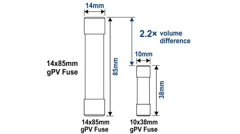
– 12 × 15A gPV fuses (string-level protection)
– 1 × 200A main disconnect switch
– Positive and negative bus bars (rated 200A continuous)
– SPD mounting for Type 2 surge arrester
– Enclosure: NEMA 4X stainless steel, IP66
Pricing: $600-$2,500 depending on string capacity and features
Conception:
– Heavy-duty switch mechanism rated for breaking full-load current
– Arc interruption features (magnetic blowout, arc chutes)
– Modular construction (DIN rail or bolt-mount)
– Available with integrated fuses or separate overcurrent protection
Avantages:
✅ Rated for full-load interruption (not just isolation)
✅ Compact design for high current (400-1600A)
✅ Modular (can expand or reconfigure)
✅ Long mechanical life (20,000+ operations)
Inconvénients:
❌ Expensive ($800-$5,000 per disconnect)
❌ Requires technical knowledge to select and install
❌ May require separate weatherproof enclosure
Typical Applications:
– Utility-scale solar (1-100 MW)
– Central inverter DC inputs (1000-1500V DC, 500-1600A)
– Combining multiple combiner boxes to main disconnect
Product Examples:
- Mersen MPDB series: 250-1600A, 1500V DC, load-break rated
- Littelfuse PV1500 series: 400-1250A, 1500V DC, DIN rail mount
- Eaton Bussmann DCM series: 200-800A, 1000V DC, modular
Pricing: $800-$5,000+ depending on current rating and features
Conception:
– Electric or pneumatic actuator operates disconnect remotely
– Control via SCADA, building management system, or dedicated control panel
– Position feedback (open/closed status transmitted)
– Manual override for emergency operation
Avantages:
✅ Remote operation (no personnel at switch location)
✅ Automated shutdown sequences possible
✅ Rapid response to emergency conditions
✅ Integration with fire alarm systems (automatic PV shutdown)
Inconvénients:
❌ Complex installation (control wiring required)
❌ Expensive ($1,500-$8,000 per disconnect)
❌ Requires maintenance (motor/actuator servicing)
❌ Control power dependency (battery backup recommended)
Typical Applications:
– Rapid shutdown systems (NEC 690.12 compliance)
– Fire department emergency disconnect (rooftop access)
– Large arrays where manual operation impractical
– Integration with automated control systems
Rapid Shutdown Requirement (NEC 690.12):
2017 NEC and later require PV systems to reduce conductor voltage to ≤80V within 10 feet of array and ≤30V everywhere else within 30 seconds of shutdown initiation. Motorized disconnects can satisfy this when combined with module-level power electronics or special string inverters.
Pricing: $1,500-$8,000 depending on current rating and automation features
Lockout/Tagout (LOTO) Purpose:
Prevents unexpected energization of equipment during maintenance by:
1. Lockout: Physical device (padlock) prevents operation
2. Tagout: Warning label identifies who locked out and why
Solar-Specific Challenges:
Unlike typical industrial equipment that can be fully de-energized:
- PV arrays cannot be “turned off”—they generate voltage whenever light hits cells
– Disconnect isolates array from equipment, but array remains energized
– Requires understanding of multiple energy sources (PV, battery, grid backfeed)
Step 1: Preparation
– Identify all energy sources: PV array, battery bank (if present), grid connection
– Identify all disconnects required for isolation
– Notify affected personnel: “PV system will be shut down 2:00-5:00 PM today”
– Gather LOTO materials: Padlocks (one per authorized employee), tags, voltage tester
Step 2: Shutdown
– Stop system normally if possible: Use inverter shutdown procedure first
– Reduces arc potential when opening disconnects under load
– Example: Place inverter in “standby” mode before opening DC disconnect
Step 3: Isolation
Open disconnects in correct sequence:
1. AC disconnect (inverter output) – First
2. DC inverter disconnect (DC input) – Second
3. Building disconnect (if needed) – Third
4. Déconnexion de la batterie (if applicable) – As needed
Raison d'être: Opening AC side first prevents backfeed, then DC side isolates array.
Step 4: Lockout Application
For each opened disconnect:
– Insert padlock through hasp (or use lockout device if no integral hasp)
– Each authorized employee applies their OWN padlock
– Multiple workers = multiple padlocks on same disconnect (lockout hasps accommodate 3-6 padlocks)
Key Rule: One Person, One Lock – Each worker installing their personal padlock ensures they control the energy isolation.
Step 5: Tagout Application
Attach tag to each locked-out disconnect:
Danger Tag Information:
– “DANGER – DO NOT OPERATE”
– Equipment identification: “Inverter #3 DC Disconnect”
– Reason: “Inverter maintenance in progress”
– Employee name: “John Smith, Technician #45”
– Date/Time: “10/15/2025, 2:00 PM”
– Contact: “Call 555-1234 before operating”
Step 6: Verification
Critical Safety Step:
1. Attempt to operate equipment (should not start—disconnect locked out)
2. Test for voltage using appropriate DC voltage meter (rated ≥ system voltage)
3. Measure at equipment terminals (NOT at disconnect load side)
4. Expected: 0V DC
5. If voltage present: Investigate why isolation failed before proceeding
Zero Energy State Verification:
Pour inverter maintenance:
– Test DC input terminals: Should read 0V (array isolated by disconnect)
– Test AC output terminals: Should read 0V (AC disconnect open)
– Test control power: Should read 0V (control transformer isolated)
Pour combiner box maintenance:
– Test bus bar downstream of array disconnect: Should read 0V
– ⚠️ Individual string terminals WILL have voltage (strings cannot be turned off)
– If working on string fuses: Cover modules with opaque material to reduce voltage
Step 1: Workspace Clear
– Remove all tools and materials
– Replace all guards and covers
– Verify equipment ready to return to service
Step 2: Personnel Clear
– Confirm all workers have left hazardous area
– Communication: “Inverter work complete, preparing to energize”
Step 3: Remove LOTO Devices
– Each employee removes their OWN lock only
– Final lock removed by person who initiated LOTO
– Remove tags after locks removed
Step 4: Notification
– Notify affected employees: “PV system returning to service”
– Operator communication: “Ready to close disconnects”
Step 5: Restore Energy
– Close disconnects in REVERSE sequence from shutdown:
1. Battery disconnect (if opened)
2. Building disconnect
3. DC inverter disconnect
4. AC disconnect
– Verify system operation normal

Formule (from NEC 690.17):
I_disconnect ≥ 125% of maximum circuit current
Where maximum circuit current = I_sc × 1.25 (high irradiance factor)
Combined: I_disconnect ≥ I_sc × 1.56
Example 1: Single String
– Module: I_sc = 11.2A
– Required: 11.2A × 1.56 = 17.47A
- Sélectionné : 30A disconnect (smallest standard size ≥ 17.47A)
Example 2: Multiple Parallel Strings
– System: 10 strings in parallel
– Module I_sc = 11.2A per string
– Combined I_sc = 10 × 11.2A = 112A
– Required: 112A × 1.56 = 174.7A
- Sélectionné : 200A disconnect
Temperature Adjustment:
If disconnect located in high-temperature environment (rooftop, direct sun):
Adjusted Rating: I_disconnect_adj = I_required / k_temp
Where k_temp = temperature correction factor:
– 40°C: 0.96
– 50°C: 0.91
– 60°C: 0.86
Example with Temperature:
– Required: 174.7A (from calculation above)
– Disconnect location: Rooftop, estimated 55°C ambient
– k_temp ≈ 0.88 (interpolated between 50°C and 60°C)
– Adjusted: 174.7A / 0.88 = 198.5A
- Sélectionné : 200A disconnect (marginally adequate)
– Better choice: 400A disconnect (provides 100% margin at high temperature)
Exigence:
V_disconnect ≥ V_oc_max (at lowest expected temperature)
Temperature Effect on V_oc:
V_oc increases approximately 0.3-0.5% per °C below 25°C (varies by technology):
Formule:
V_oc_max = V_oc_STC × [1 + β_Voc × (T_min – 25°C)]
Où ?
– V_oc_STC = open-circuit voltage at standard test conditions (25°C)
– β_Voc = temperature coefficient (%/°C), typically -0.28% to -0.45%/°C
– T_min = lowest expected ambient temperature
Exemple de calcul:
Système: 20 modules in series
– Module V_oc_STC = 44V (from datasheet)
– Temperature coefficient: -0.35%/°C
– String V_oc at 25°C: 20 × 44V = 880V
– Location: Denver, Colorado, coldest temp: -20°C
V_oc_max = 880V × [1 + (-0.0035) × (-20 – 25)]
= 880V × [1 + (-0.0035) × (-45)]
= 880V × [1 + 0.1575]
= 880V × 1.1575
= 1019V
Disconnect Voltage Rating Required: ≥1019V DC
Standard Ratings Available:
– 600V DC (insufficient!)
– 1000V DC (marginal—only 2% margin)
– 1500V DC ✓ (recommended—47% margin)
⚠️ Safety Margin: Always select disconnect voltage rating with ≥20% margin above calculated V_oc_max. Cold temperatures can exceed design assumptions, and inadequate voltage rating can cause catastrophic disconnect failure.
Location Determines Required Protection:
Indoor Installations (equipment room, basement):
- NEMA 1 / IP20: Basic enclosure, prevents accidental contact
– Cost: Lowest
– Protection: Fingers and large objects only
– Ventilation: Open (natural cooling)
Outdoor Weather-Resistant (rooftop, wall-mount):
- NEMA 3R / IP54: Rain-tight, sleet-resistant
– Cost: Moderate
– Protection: Prevents water entry from rain (not submersion)
– Ventilation: Drain holes at bottom
– Most common for residential solar disconnects
Outdoor Dust/Water-Tight (ground-mount, coastal):
- NEMA 4X / IP66: Dust-tight, water-tight, corrosion-resistant
– Cost: Higher
– Protection: Prevents dust accumulation, withstands hose-directed water
– Materials: Stainless steel or fiberglass-reinforced polymer
– Recommended for: Coastal installations (salt spray), dusty environments (agriculture, desert)
Comparison Table:
| Evaluation | Protection contre la poussière | Protection de l'eau | Corrosion Resistance | Application typique |
|---|---|---|---|---|
| NEMA 1 / IP20 | Minimal | Aucun | Standard paint | Indoor only |
| NEMA 3R / IP54 | Limité (non étanche à la poussière) | Rain, sleet (not submersion) | Powder coat paint | Outdoor residential |
| NEMA 4X / IP66 | Etanche à la poussière | Eau dirigée par un tuyau | Stainless steel or polymer | Coastal, industrial, harsh |
Impact sur les coûts:
– NEMA 1: $80-$200 (100A disconnect example)
– NEMA 3R: $120-$280 (+40-50% vs NEMA 1)
– NEMA 4X: $200-$450 (+150-200% vs NEMA 1)
A solar disconnect is primarily a safety isolation device for maintenance, providing visible contact separation and lockout/tagout capability, while a circuit breaker is an automatic overcurrent protection device. Disconnects are manually operated switches designed for human interaction—they create a visible air gap (3-12mm) you can see through a viewing window, include padlock hasps for lockout during maintenance, and are NOT designed for repeated opening under full-load conditions. Circuit breakers automatically trip when current exceeds rating, provide arc interruption for fault currents, and can be reset multiple times. Per NEC, solar systems require BOTH: overcurrent protection (breakers/fuses per NEC 690.9) AND disconnecting means (manual disconnects per NEC 690.13-690.17). Some breakers can serve as disconnects IF they provide visible break or positive position indication AND are lockable in open position, but dedicated disconnect switches provide better safety verification for maintenance procedures.
Minimum 2-3 disconnects required by NEC: (1) Building disconnect (NEC 690.13) at point where PV conductors enter building—provides emergency shutdown accessible to building occupants/fire department; (2) Equipment disconnect (NEC 690.15) within sight of inverter OR remote lockable—allows safe inverter maintenance; (3) Déconnexion de la batterie (NEC 690.71) if system includes battery storage—isolates battery for maintenance. Large commercial systems may include additional disconnects: array disconnect at combiner box, string-level isolation switches, AC disconnect at inverter output. Each disconnect serves specific isolation purpose—cannot be eliminated by combining functions. Common residential configuration: combiner with disconnect at array + building disconnect at service entrance + DC/AC disconnects at inverter = 3-4 total disconnects. Complexity increases with system size, but every disconnect must be labeled, lockable, and accessible per code.
No—AC-rated disconnects are NOT safe for DC solar use due to fundamental arc extinction differences. AC disconnects rely on current naturally crossing zero 100-120 times per second where arcs self-extinguish. DC has no zero-crossings; arcs sustain continuously and require specialized technology: extended contact gaps (8-15mm vs 3-5mm AC), magnetic blowout arc chutes, double-break contacts, and arc-resistant materials. An AC disconnect rated 240V AC typically handles only 60-125V DC—using it for 600-1500V DC solar risks catastrophic failure: sustained arc may weld contacts closed (cannot turn off), explode enclosure, or ignite fire. Always verify disconnect marked with DC voltage rating ≥ system V_oc_max. Common misconception: “600V AC = 600V DC”—completely FALSE due to arc behavior differences. Only purchase disconnects explicitly rated for DC voltage at or above your system’s maximum open-circuit voltage. Cost difference minimal but safety difference is life-or-death.
Lockout/tagout (LOTO) is OSHA-mandated safety procedure (1910.147) preventing unexpected equipment energization during maintenance. Lockout = physical device (padlock) prevents disconnect operation; Tagout = warning label identifies who locked out, why, and contact info. Required because photovoltaic arrays cannot be “turned off”—they generate voltage whenever light hits cells, even cloudy days generate 30-50% of rated voltage. LOTO procedure for solar: (1) Open disconnect isolating equipment; (2) Each authorized employee applies personal padlock (one person, one lock rule); (3) Attach danger tag with employee name, date, reason; (4) Test for voltage to verify isolation (critical—confirms disconnect actually opened); (5) After work complete, each employee removes ONLY their own lock. Multi-person jobs require multi-lock capability (lockout hasps accommodate 3-6 padlocks). Solar-specific challenge: array-side conductors remain energized even with disconnect open—must cover modules with opaque material if working on string wiring. Failure to LOTO causes 10-15% of electrical fatalities annually—never skip this procedure.
Use NEC 690.17 formula: I_disconnect ≥ I_sc × 1.56 where I_sc is module short-circuit current (or combined I_sc for multiple parallel strings). The 1.56 factor accounts for high irradiance conditions (1.25×) and continuous operation derating (1.25×), giving 1.25 × 1.25 = 1.56 total. Example: system with 8 parallel strings, module I_sc = 11A each. Combined I_sc = 8 × 11A = 88A. Required disconnect: 88A × 1.56 = 137.3A minimum. Select next standard rating above: 200A disconnect. Temperature consideration: if disconnect located in high-temp environment (rooftop, direct sun), apply additional derating. At 60°C ambient, multiply required current by 1.15-1.20 to compensate for reduced capacity. Same example at 60°C: 137.3A × 1.15 = 157.9A still fits in 200A rating, but provides less margin—consider 400A for severe environments. Always round UP to next standard size, never down. Standard disconnect ratings: 30A, 60A, 100A, 200A, 400A, 800A.
Visible break means you can physically see the air gap between open contacts without disassembling the disconnect—typically through transparent window in enclosure or external viewing port. NEC 690.13(C) requires disconnects provide “means for visually determining position of contacts” for personnel safety. Why critical: during maintenance, technician’s life depends on disconnect being open. Handle position alone insufficient—internal mechanism can fail (broken linkage, corroded contacts stuck closed) while handle appears “OFF”. Visible break provides direct verification: looking through window, see 8-12mm air gap between contacts = confirmed isolation. Alternative: positive position indication (mechanical indicator directly linked to contacts, not just handle). Solar systems operate at 400-1500V DC—invisible, odorless, silent, and DEADLY. Cannot “sense” voltage like 120V AC tingle warning. Visible break or positive indication prevents the worst-case scenario: technician assumes disconnect open based on handle, contacts actually closed, touches “de-energized” bus bar at 800V DC = electrocution. Always verify visible break OR test voltage before touching any conductors. Never trust handle position alone.
Yes—systems >1000V DC require disconnects with higher voltage ratings and enhanced safety features. As residential/commercial systems trend toward 1500V DC (reduces wire size, increases efficiency), disconnect technology must match. Requirements for 1000-1500V DC: (1) Voltage rating ≥ V_oc_max with 20% minimum margin; (2) Increased contact gap 12-20mm (vs 6-10mm for 600V) to prevent arc re-strike; (3) Double-break contacts in some designs—two gaps in series doubles effective arc extinction voltage; (4) Enhanced insulation between phases and to ground; (5) Arc-resistant enclosure materials per IEEE C37.20.7 for indoor installations. Product availability improving as 1500V becomes standard: manufacturers like Mersen, Eaton, ABB offer 1500V DC rated disconnect switches. Cost premium: 1500V disconnects typically 30-50% more expensive than 600-1000V equivalents due to specialized construction. NEC 2017 and later simplified >1000V installations (previously required special permits), making 1500V residential-commercial systems code-compliant nationwide. Always specify exact voltage rating when purchasing—don’t assume “high voltage” model covers 1500V without checking datasheet.
Solar disconnects represent mandatory safety technology enabling personnel protection through visible, physical electrical isolation during maintenance operations on photovoltaic systems. Unlike automatic protection devices (fuses, breakers) that interrupt faults, disconnects are manually-operated isolation switches specifically designed for safe human interaction, lockout/tagout procedures, and code-required emergency shutdown capability.
Key Disconnect Fundamentals:
Visible Break Safety: The defining feature separating disconnects from breakers is visible contact separation—ability to physically see 6-12mm air gap through enclosure window, providing definitive verification of electrical isolation. NEC 690.13(C) mandates this feature because technician safety depends on confirmed isolation, not just handle position indicators that can fail mechanically. Always verify visible break OR test for zero voltage before touching conductors.
Multi-Level Isolation: Typical solar installations require 2-4 disconnects serving different functions: building disconnect (NEC 690.13) for emergency shutdown at service entrance, equipment disconnect (NEC 690.15) within sight of inverter for maintenance, array disconnect at combiner box for string-level work, and battery disconnect (NEC 690.71) if storage present. Each disconnect enables isolation of specific equipment while other parts of system remain operational.
DC-Specific Construction: Solar disconnects employ specialized technology for reliable DC arc interruption: extended contact gaps (2-3× longer than AC), magnetic blowout arc chutes, double-break contacts for >1000V systems, and arc-resistant materials. Never substitute AC-rated disconnects—240V AC switch typically handles only 60-125V DC due to sustained arc challenges. Always verify DC voltage rating ≥ system V_oc_max.
Proper Sizing Methodology: Calculate disconnect current rating per NEC 690.17: I_disconnect ≥ I_sc × 1.56 (accounts for high irradiance and continuous operation). Voltage rating must exceed V_oc_max at coldest expected temperature (V_oc increases ~0.35%/°C below 25°C). Apply temperature derating for disconnects in hot environments (rooftop installations may reach 50-60°C, reducing effective capacity 10-15%).
Lockout/Tagout Integration: OSHA 1910.147 requires LOTO procedures for maintenance on energized equipment. Solar disconnects must provide lockout capability (padlock hasp accommodating multiple locks) and tagout provisions. Critical difference from industrial equipment: PV arrays cannot be “turned off”—disconnects isolate array from equipment but array-side conductors remain energized, requiring enhanced safety procedures including voltage testing and module covering when necessary.
For solar installers, facility maintenance personnel, and system owners, understanding disconnect technology, code requirements, and safety procedures prevents electrical shock hazards during routine maintenance operations throughout 25-30 year system lifespans. Proper disconnect selection, installation, and use represents the foundation of solar electrical safety.
Related Solar Safety Resources:
- Solar Fuses Protection – Overcurrent protection fundamentals
- Disjoncteurs DC – Automatic protection devices
- Conception d'une boîte de raccordement PV – System integration and protection
Safety Compliance Support: SYNODE provides NEC compliance verification services, disconnect specification review, and lockout/tagout procedure development for solar installations. Contact our safety engineering team for project-specific consultation and code compliance documentation.
Dernière mise à jour : Octobre 2025
Auteur : SYNODE Safety Engineering Team
Examen technique : NABCEP Certified Installers, OSHA Safety Specialists
Références du code : NEC Article 690:2023, OSHA 1910.147:2024, NFPA 70E:2024