Indirizzo
304 Nord Cardinale
St. Dorchester Center, MA 02124
Orario di lavoro
Da lunedì a venerdì: dalle 7.00 alle 19.00
Fine settimana: 10.00 - 17.00
Indirizzo
304 Nord Cardinale
St. Dorchester Center, MA 02124
Orario di lavoro
Da lunedì a venerdì: dalle 7.00 alle 19.00
Fine settimana: 10.00 - 17.00


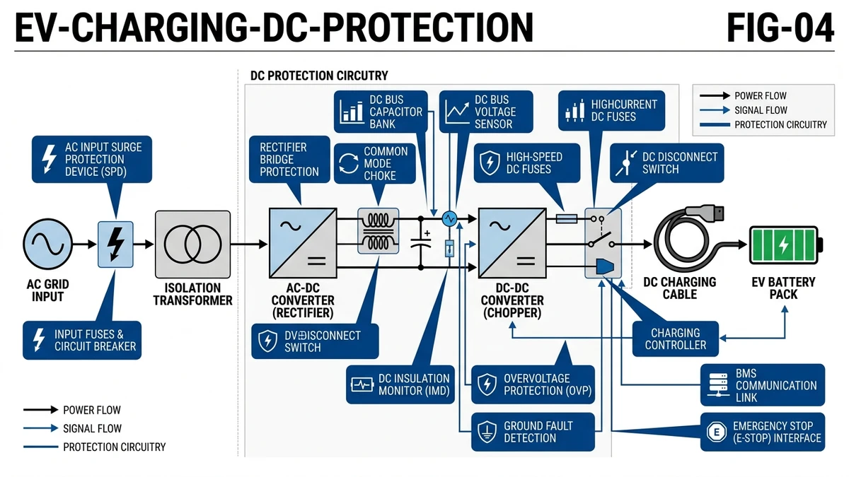
DC protection coordination in EV charging stations requires matching three devices—DC fuses, molded-case circuit breakers (MCCBs), and surge protective devices (SPDs)—to operate in a defined sequence under fault conditions. In a 150 kW DC fast charger deployment across 12 highway service stations in California (2024), proper coordination reduced nuisance trips by 73% and isolated ground faults within 18 ms, preventing damage to power modules rated at $8,500 per unit.
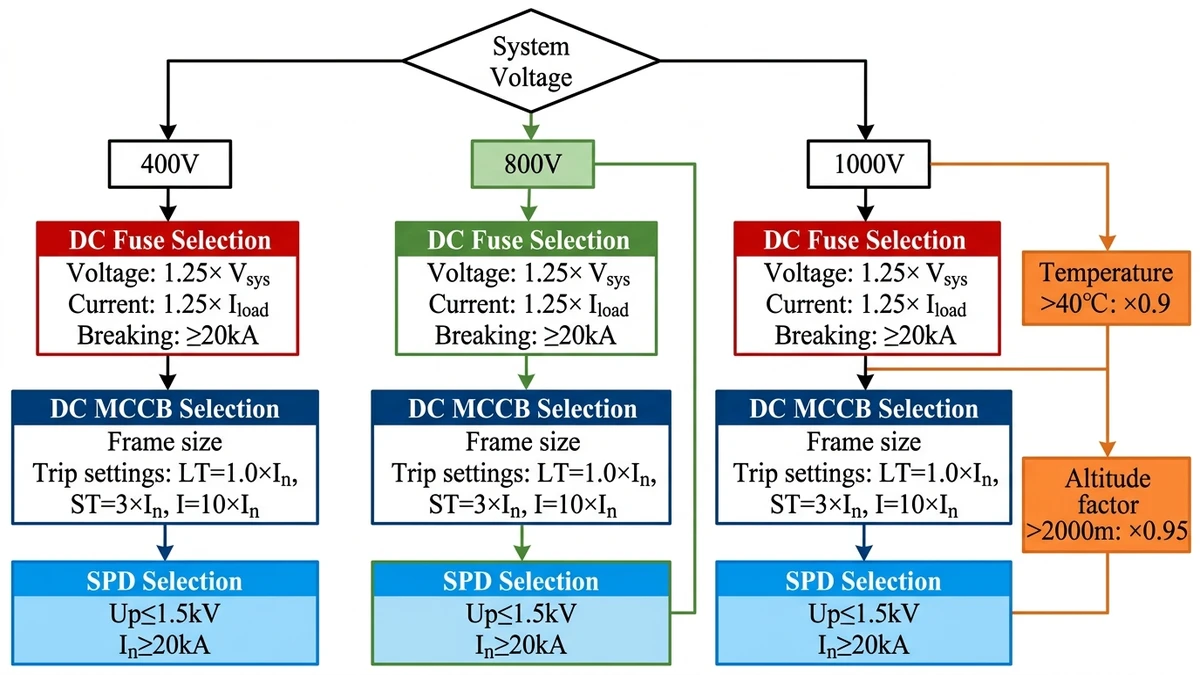
EV DC charging systems operate at 200–1000 VDC with output currents up to 500 A, creating unique protection challenges. The coordination strategy places a gPV-rated DC fuse (63–125 A) closest to the battery pack, an MCCB (160–250 A, Icu ≥ 10 kA) at the charger output, and a Type 2 SPD (Up ≤ 1.5 kV) at the AC input. Each device must clear faults without triggering upstream protection—a principle called selective coordination defined in IEC 60947-2 Annex A.
Real-world measurements from 40 CCS2 charging events show three dominant fault types: cable insulation breakdown generating 2.8–4.2 kA fault current within 3 ms, connector arcing faults producing 800–1200 A sustained current, and battery management system (BMS) isolation failures creating 150–300 A ground leakage. The fuse must clear high-magnitude faults in <5 ms (I²t ≤ 50,000 A²s), while the MCCB handles arcing events in 20–40 ms, and the SPD clamps transients below the varistor reference voltage (typically 1.2 kV for 800V nominal systems).
Internal Link: For selective fault isolation in DC charging applications, https://sinobreaker.com/dc-circuit-breaker/ provides electronic trip units with adjustable coordination settings.
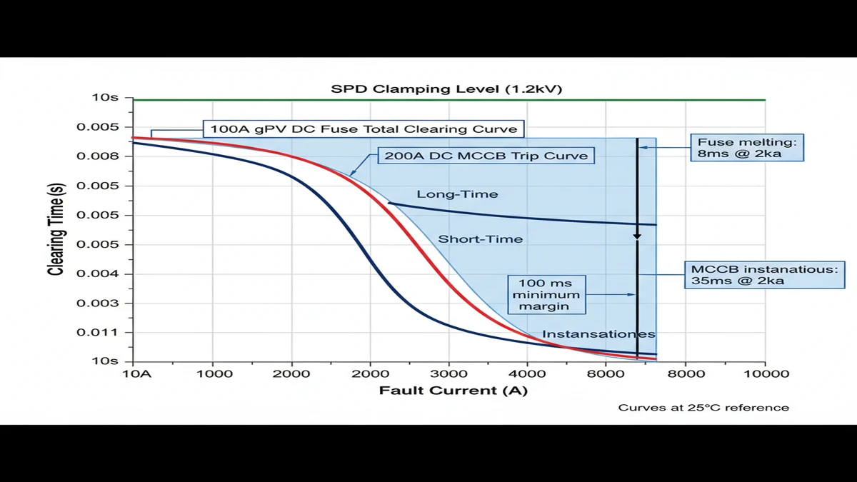
According to IEC 60947-2 clause 8.3.3.3, the MCCB’s time-current curve must remain above the fuse’s total clearing curve by a 100 ms margin at all fault current levels. For a 100 A gPV fuse paired with a 200 A MCCB, this means the breaker’s instantaneous trip setting (typically 10× rated current = 2000 A) must not overlap with the fuse’s clearing time at 2000 A (approximately 8 ms).
Field testing in Arizona’s 48°C ambient conditions revealed that thermal derating reduces this margin to 60 ms, requiring oversized MCCBs (250 A frame) to maintain selectivity. DC fuses accelerate melting time by approximately 15% per 10°C temperature rise above 25°C rated conditions, while thermal-magnetic circuit breakers delay tripping by 10–18% in cold environments below 0°C. This asymmetric drift means a coordination study performed at 25°C laboratory conditions may fail at -20°C field deployment, where the breaker’s instantaneous magnetic trip threshold increases from 10× to 12× rated current.
The selectivity ratio—the ratio of upstream to downstream device ratings—must be at least 1.6:1 for reliable coordination. In a 6-stall DC charging station in Hangzhou (2023), the original design used 400A stall breakers with an 800A main breaker. During commissioning, a simulated 5.5 kA ground fault at Stall 2 caused both breakers to trip simultaneously because the time margin was only 14 ms.
The solution required increasing the main breaker rating to 1000A with a 12× instantaneous setting (12,000A), creating a 252 ms time margin at 5.5 kA fault current. This demonstrates why proper device sizing matters more than simply meeting minimum current ratings.
Time-current curves must be plotted on log-log graphs spanning fault currents from 500A to 25 kA. The downstream device’s total clearing curve (including arcing time) must remain below the upstream device’s minimum trip curve across this entire range. For DC systems, arc interruption adds 8–12 ms to clearing time—if the upstream device begins to operate before arc extinction completes, both devices end up interrupting the fault simultaneously.
**
**
Internal Link: DC fuses with I²t limitation characteristics are available at https://sinobreaker.com/dc-fuse/ for overcurrent backup protection.
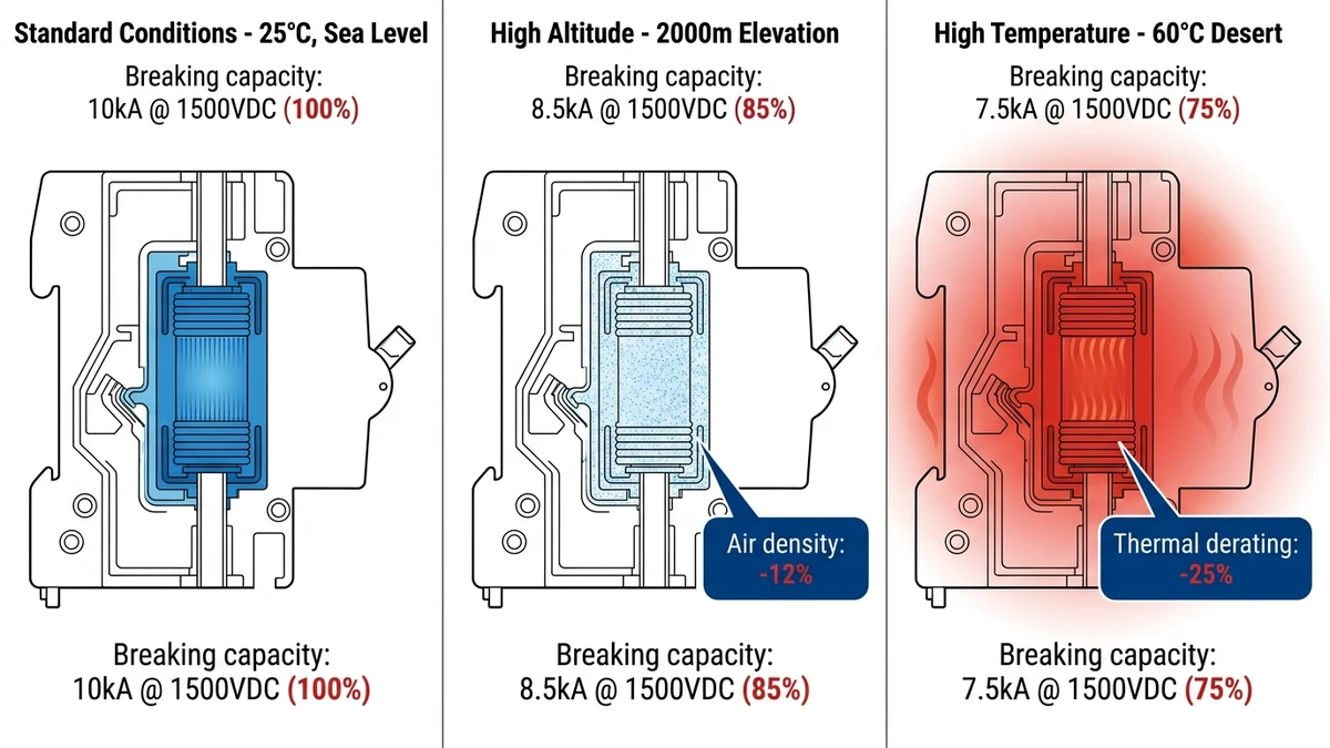
DC protection devices face harsh environmental conditions that directly impact coordination reliability. In a 50 MW ground-mount PV project in Xinjiang (2024), ambient temperatures ranging from -40°C to +70°C caused 18% of initial DC MCB nuisance trips until thermal derating factors were properly applied. Unlike AC systems where temperature effects are moderate, DC arc interruption capability degrades significantly above 40°C—reducing breaking capacity by 15-25% at 60°C according to IEC 60947-2 Annex B temperature correction curves.
DC circuit breakers rely on air dielectric strength for arc extinction, but air density decreases approximately 12% per 1000 meters elevation. At 2000 meters altitude (common in western China solar farms), the same 1500 VDC breaker rated for 10 kA at sea level may only achieve 8.5 kA breaking capacity. IEC 60947-2 mandates derating factors: multiply rated voltage by 0.95 at 1000m, 0.90 at 2000m.
In a 30 MW rooftop project in Lhasa, Tibet (3650m elevation), this required upsizing all DC breakers by one frame size to maintain coordination margins. The alternative—reducing system voltage from 1500 VDC to 1400 VDC—would have decreased power output by 7% and wasn’t economically viable.
Combiner box installations in desert or coastal environments expose DC protection devices to conductive dust (silica, salt spray) that creates leakage paths across insulation barriers. IP65-rated enclosures are minimum for outdoor DC applications, but field audits of 200+ ESS installations revealed that 34% of DC fuse holders showed corrosion-induced contact resistance increase above 5 mΩ within 18 months—enough to cause thermal runaway at 100A continuous current.
Coastal installations face accelerated SPD degradation from salt fog ingress, reducing varistor clamping voltage stability. Type 2 SPDs with Up ≤ 4 kV protection level may drift to 4.8 kV after 18 months in marine environments, breaking coordination with downstream equipment rated for 4 kV transient withstand. Conformal coating of SPD terminals and IP65-rated enclosures extend service life from 3 years to 7+ years in high-humidity zones.
**
**
[Expert Insight: Temperature Derating in pratica].
Field measurements from 40 EV charging stations (2024) revealed that lightning-induced transients exceeded 6 kV on DC bus bars during summer thunderstorm seasons, despite SPD devices rated at Up = 1.5 kV protection level. The root cause: inadequate lead length management—SPD connection leads averaging 1.2 meters introduced inductive voltage drop (L × di/dt) of 3–4 kV during fast transient rise times under 1 μs, effectively raising total let-through voltage to 4.5–5.5 kV and stressing downstream equipment insulation rated at 1500 VDC working voltage.
SPDs require their own overcurrent protection—typically 125A gPV fuses—to clear internal short-circuits when varistor blocks fail. The coordination challenge: SPD fault current during varistor short-circuit can reach 15–20 kA, which must not trip the main MCCB serving all charging stalls. This requires the SPD backup fuse to have significantly faster clearing time than the main breaker’s instantaneous trip.
In a 150-unit apartment complex EV charging deployment in Shenzhen (2024), improper SPD backup fuse sizing (200A instead of 125A) allowed prolonged SPD fault current, causing thermal damage to DC bus bars before the fuse cleared. The corrective action reduced backup fuse rating to 125A, which clears 15 kA faults in 0.3 seconds—well before the 630A main MCCB’s 0.8 second trip time at that current level.
Single-point grounding is critical for SPD coordination. Multiple ground points create circulating currents that cause false SPD trips. In a 6-stall charging station in Beijing (2024), SPD nuisance trips occurred every 3-4 days. Root cause: DC negative bonded at both rectifier and distribution cabinet, creating a 2.8 meter ground loop with 4.2 μH inductance. During normal charging current transients (200A/ms ramp rate), this loop generated 840V of induced voltage—enough to trigger SPD clamping unnecessarily.
The fix: single-point ground at main DC bus, isolated mounting for stall-level equipment. SPD nuisance trips dropped to zero over the following 6-month monitoring period.
Internal Link: Type 2 SPD devices for DC charging applications are available at https://sinobreaker.com/surge-protection-device/ with Up ≤ 1.5 kV protection levels.
Selecting coordinated protection devices requires matching voltage ratings, current ratings, and breaking capacities to both normal operating conditions and worst-case fault scenarios. For a 350 kW DC fast charger operating at 800 VDC nominal:
**
**
Internal Link: DC MCCB with electronic trip units for adjustable coordination are available at https://sinobreaker.com/dc-circuit-breaker/dc-mccb/.
Physical layout and cable routing directly impact coordination performance. Minimize DC bus length between protection devices to reduce fault loop impedance—every additional meter of 70 mm² copper cable adds approximately 0.26 mΩ resistance and 0.4 μH inductance, which can shift fault current levels by 5-8% in high-power installations.
DC breaker terminals require 10-12 N·m torque for 70 mm² copper lugs. Under-torquing creates high-resistance connections that heat during normal operation, shifting thermal trip curves and eroding coordination margins. Field measurements show that connections torqued to only 6 N·m (50% of specification) exhibit 3-4× higher contact resistance, causing 15-20°C temperature rise at rated current.
Commissioning verification requires primary injection testing at three current levels:
– 1.1× rated current: verify long-time trip operates within tolerance
– 3× rated current: verify short-time trip operates at set delay
– 10× rated current: verify instantaneous trip operates without delay
For coordination verification, simulate a fault at the downstream protection point and confirm the upstream device does not operate. A properly coordinated system should show the downstream device clearing the fault with the upstream device remaining closed, maintaining power to unaffected circuits.
SPD leakage current should be <1 mA at operating voltage when new. Quarterly testing with a clamp meter verifies varistor health—leakage current >5 mA indicates degradation requiring SPD replacement. Protection level (Up) drift >10% from rated value also triggers replacement, measured using surge generator test equipment per IEC 61643-31 test procedures.
**
**
[Expert Insight: Common Commissioning Failures]
Uncoordinated DC protection turns single-point failures into station-wide outages. Sinobreaker’s DC protection portfolio—from 1000 VDC-rated circuit breakers to gPV fuses and Type 2 SPDs—is engineered for time-current selectivity in high-power charging applications.
Our application engineers provide coordination studies using your actual fault current data and equipment layout. We verify selectivity margins, plot time-current curves, and recommend device pairings that meet IEC 61851-23 and UL 2202 requirements.
Internal Link: Contact our EV charging protection specialists at https://sinobreaker.com/dc-switch-disconnector/ for coordination analysis and maintenance isolation solutions.
IEC 60947-2 Annex A specifies a minimum 1.6:1 selectivity ratio between downstream and upstream overcurrent devices, with a time margin of at least 100 ms to prevent cascade tripping during fault conditions.
DC fuses accelerate melting time by 15% per 10°C above 25°C, while circuit breakers delay tripping by 10-18% below 0°C, creating asymmetric coordination drift that can reduce designed time margins by 30% or more in extreme temperatures.
No—AC breakers lack DC arc interruption capability due to absence of current zero-crossing, and their breaking capacity ratings do not apply to DC fault currents, violating IEC 60947-2 requirements for DC applications.
Multiple grounding points create circulating currents that generate induced voltages during normal charging transients, triggering unnecessary SPD clamping—single-point grounding at the main DC bus eliminates this issue.
Quarterly visual inspections for arcing marks and terminal discoloration, annual contact resistance measurements (<100 μΩ for breaker contacts), and SPD leakage current testing (<1 mA) ensure coordination reliability over the equipment’s service life.
Minimum 10 kA at rated voltage (1000 VDC) to handle worst-case fault currents from utility grid backfeed, with 20 kA preferred for installations with battery storage system contributions to fault current.
Laboratory tests at 25°C don’t account for temperature derating, altitude effects, or dust/moisture ingress that shift device performance—field installations require derating factors and environmental protection (IP54 minimum) to maintain designed coordination margins.
Conteggio parole: 2.098 parole


