Indirizzo
304 Nord Cardinale
St. Dorchester Center, MA 02124
Orario di lavoro
Da lunedì a venerdì: dalle 7.00 alle 19.00
Fine settimana: 10.00 - 17.00
Indirizzo
304 Nord Cardinale
St. Dorchester Center, MA 02124
Orario di lavoro
Da lunedì a venerdì: dalle 7.00 alle 19.00
Fine settimana: 10.00 - 17.00

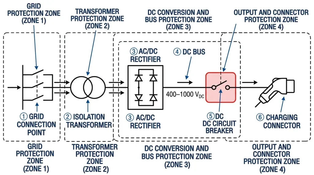
DC fast chargers operate at 400–1000 VDC with sustained currents reaching 500 A. Standard AC circuit breakers cannot safely interrupt these fault currents because DC flows continuously without the natural zero-crossing points that AC systems provide 100–120 times per second. Without zero-crossing, arcs sustain indefinitely unless forced to extinguish through specialized mechanisms—making dedicated DC circuit breakers essential for EV charging infrastructure protection.
When a fault occurs in a charging system—cable insulation failure, connector short, or internal charger malfunction—the protection device must interrupt current flow within milliseconds. An AC breaker attempting this on a DC circuit draws an arc that refuses to self-extinguish. The arc generates extreme heat, damages contacts, and creates fire and arc flash hazards.
In a 120 kW DC fast charger deployment at a logistics hub in Guangdong (2023), a cable fault occurred during commissioning. The installed Interruttore CC cleared the fault in 38 milliseconds. Post-incident analysis estimated that inadequate protection would have allowed arcing to continue for 4+ seconds—sufficient time for cable insulation ignition and enclosure damage.
DC circuit breakers designed for EV charging incorporate three features absent in AC equivalents:
These features add cost and size compared to AC breakers of equivalent current rating. The alternative—using undersized or inappropriate protection—introduces unacceptable risk where vehicles, operators, and bystanders are present.
AC current crosses zero 100–120 times per second at 50/60 Hz, providing natural arc extinction opportunities. DC current flows continuously. This fundamental difference demands entirely different interruption strategies.
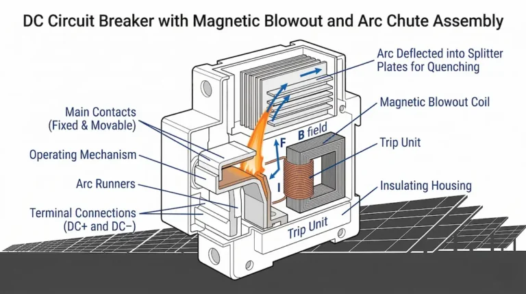
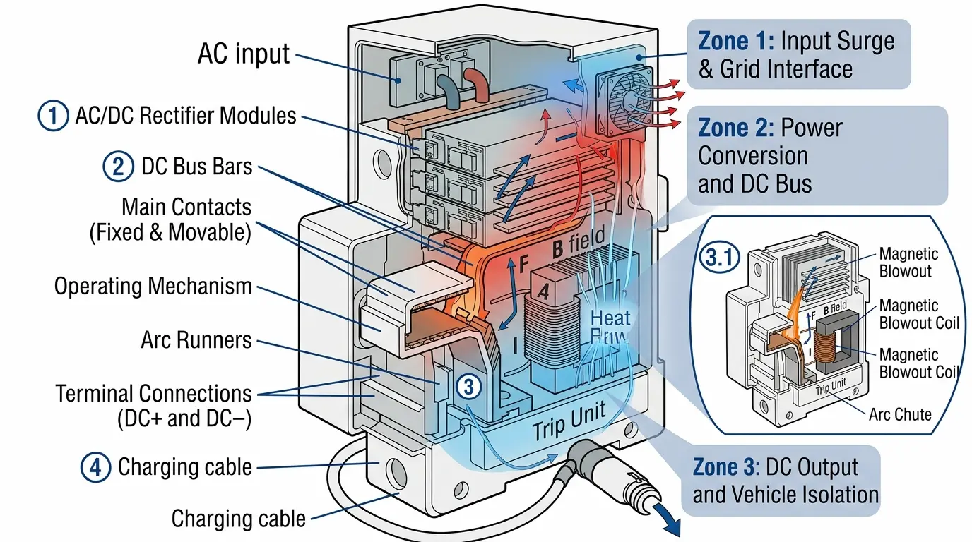
DC breakers use permanent magnets or electromagnets generating field strengths of 80–150 mT to deflect the arc away from main contacts. The magnetic field forces the arc into an elongated path, increasing resistance and voltage drop until the arc can no longer sustain itself.
DC arc extinction in EV charging applications requires magnetic blowout systems generating field strengths of 80–150 mT to deflect and elongate the arc into segmented arc chutes. At 800 VDC—the emerging standard for next-generation EV platforms—arc energy can exceed 15 kJ during fault interruption, demanding arc chute assemblies with 12–18 ceramic plates to achieve sufficient voltage drop across the arc column.
The arc chute splits a single high-energy arc into multiple smaller arcs across steel or ceramic plates. Each plate interface adds 20–30 V of arc voltage, and the combined effect extinguishes arcs that would otherwise sustain indefinitely. A 1000 VDC breaker requires significantly longer arc paths than a 500 VDC unit—typically 8–12 mm contact gaps versus 4–6 mm.
[Expert Insight: DC Arc Physics]
- Arc energy scales with system voltage squared—an 800 VDC fault releases 4× the energy of a 400 VDC fault at equivalent current
- Magnetic blowout effectiveness decreases above 85°C ambient; thermal management directly impacts breaking reliability
- Arc chute contamination from dust or moisture can extend interruption time by 30–50%
Selecting the correct DC circuit breaker starts with matching voltage and current ratings to charger specifications. Undersizing creates safety hazards; oversizing wastes budget and enclosure space.
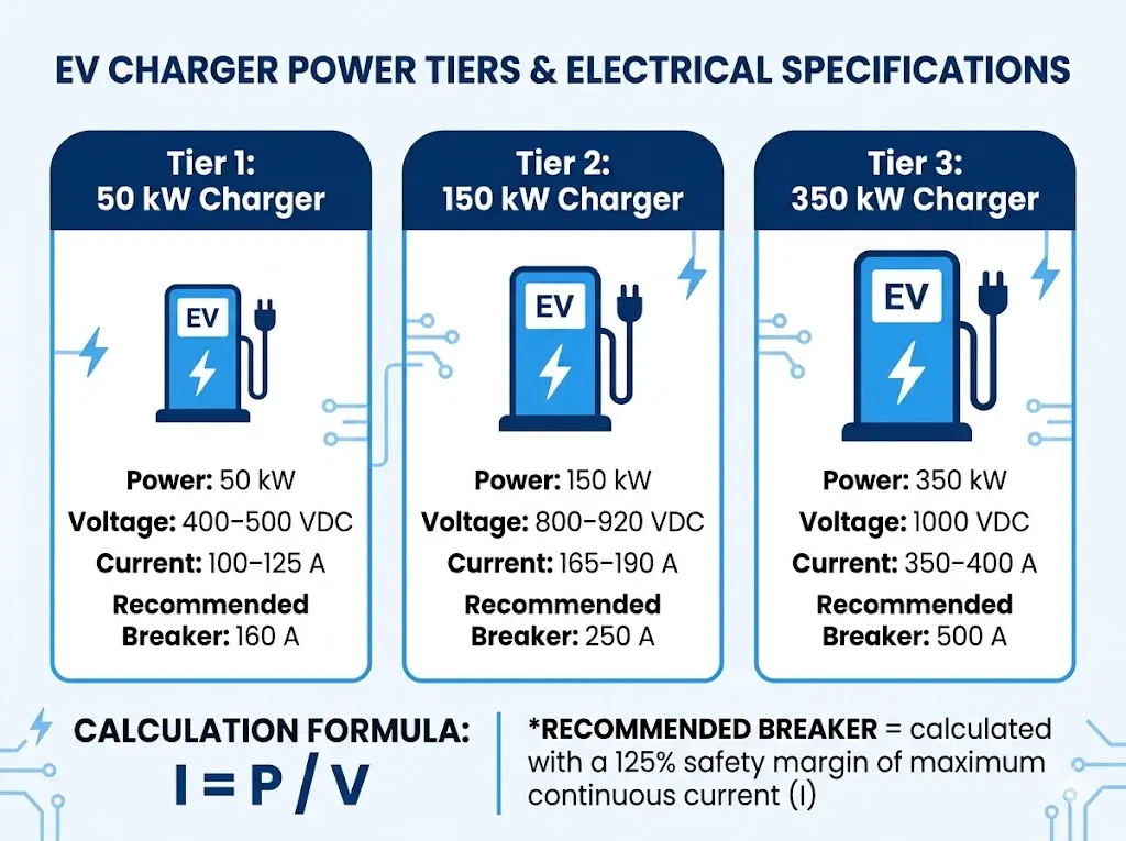
Entry-level DC fast chargers typically operate at 400–500 VDC with nominal currents of 100–125 A. A DC MCB rated 125 A at 500 VDC provides adequate protection with appropriate margin.
Mid-range fast chargers operate at 800–920 VDC, drawing 165–190 A nominal. These systems require breakers rated for 1000 VDC to accommodate voltage transients during regenerative braking feedback.
High-power chargers push system voltages to 1000 VDC with currents of 350–400 A. Two-pole or series-connected configurations may be necessary to achieve adequate voltage ratings.
| Charger Power | Typical Voltage | Nominal Current | Recommended Breaker Rating |
|---|---|---|---|
| 50 kW | 400–500 VDC | 100–125 A | 160 A / 500 VDC |
| 150 kW | 800–920 VDC | 165–190 A | 250 A / 1000 VDC |
| 350 kW | 1000 VDC | 350–400 A | 500 A / 1000 VDC |
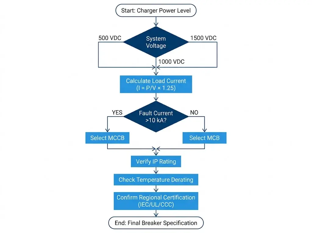
Current calculations follow I = P / V, with a 125% continuous load margin applied. A 150 kW charger at 800 V draws 187.5 A nominal; specifying a 250 A breaker provides the required margin for sustained operation.
Breaking capacity—the maximum fault current a breaker can safely interrupt—determines whether protection succeeds or fails catastrophically during a short circuit.
Icu (ultimate breaking capacity) represents the maximum fault current the breaker can interrupt once, potentially with degraded performance afterward. Ics (service breaking capacity) indicates the current level at which the breaker remains fully functional after interruption. For critical EV charging applications, specify breakers where Ics equals at least 75% of Icu.
Fault current sources in charging stations include grid contribution through the rectifier and limited battery backfeed from connected vehicles. Vehicle battery management systems typically limit backfeed current, but grid-side faults can generate substantial prospective fault currents depending on transformer sizing and cable impedance.
At a multi-unit charging plaza in Shenzhen (2024), short-circuit studies revealed 16.8 kA prospective fault current at the DC bus. The installation specified 20 kA DC MCCBs with 15% safety margin—a capacity exceeding typical DC MCB ratings.
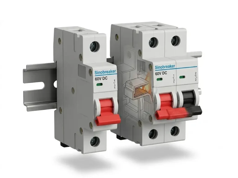
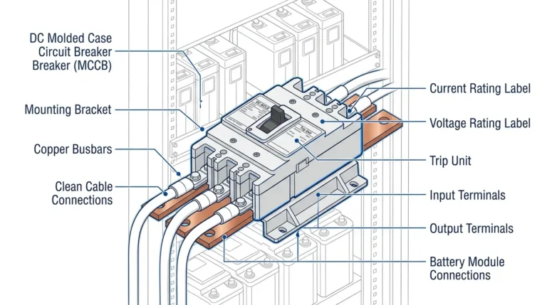
DC MCBs suit branch circuit protection up to 63 A with fixed trip settings and breaking capacities under 10 kA. DC MCCBs handle higher currents, offer adjustable trip characteristics, and provide breaking capacities up to 50 kA for main protection applications.
[Expert Insight: Fault Current Estimation]
- Prospective fault currents in charging stations typically range 10–25 kA depending on grid connection
- Short-circuit studies should account for future capacity expansion—a 4-charger site today may become 12 chargers tomorrow
- Vehicle battery backfeed is limited by onboard BMS but should not be ignored in coordination studies
Field conditions impose demands beyond electrical ratings. Breakers that perform flawlessly in laboratory tests may fail prematurely when exposed to real-world environmental stresses.
EV charging stations experience daily temperature swings that stress DC breaker components. In desert climates, enclosure temperatures reach 65°C during peak charging while dropping to 5°C overnight. This 60°C differential accelerates contact oxidation and housing seal degradation.
According to IEC 60947-2, DC circuit breakers must maintain rated performance across -25°C to +55°C ambient, with derating typically required above 40°C. Field measurements at a 350 kW charging plaza in Arizona showed internal cabinet temperatures exceeding 70°C during summer peaks, necessitating 20% current derating.
At a highway rest area station along the Hainan coast (2023), conformal-coated breakers combined with ventilated enclosures eliminated moisture-related nuisance trips over a 14-month monitoring period. Uncoated units at similar coastal sites showed contact resistance increases of 35–50% within 8 months.
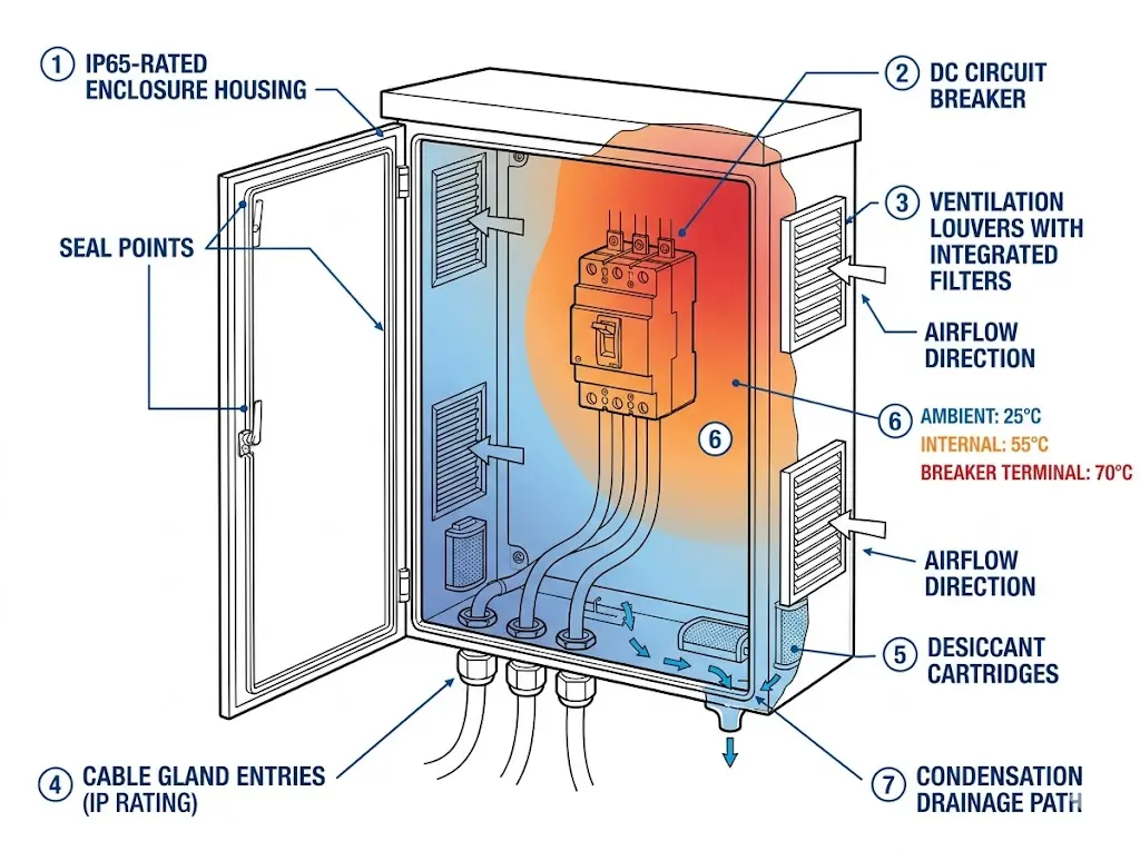
Breakers deployed within 3 km of coastlines require conformal coating on electronic trip units and stainless steel hardware to prevent galvanic corrosion. IP65-rated enclosures with breather valves and desiccant cartridges manage condensation during rapid temperature changes.
High-altitude installations above 2000 m require derating due to reduced air density affecting arc extinction capability. Thinner atmosphere provides less cooling and arc-quenching capacity. [VERIFY STANDARD: IEC 60947-2 specific clause for altitude derating factors] typically requires 10–15% current derating per 1000 m above the 2000 m threshold.
Specifying DC circuit breakers without verified standards compliance creates liability exposure and potential inspection failures. Documentation requirements vary by region but share common technical foundations.
The international standard for low-voltage circuit breakers includes Annex M specifically addressing DC applications. This annex defines test procedures for DC breaking capacity verification, requiring tests at 105% of rated voltage with proper arc energy containment. Breakers claiming DC suitability without Annex M testing may not perform as expected under actual fault conditions.
UL 489B establishes requirements for Interruttori DC intended for photovoltaic and similar DC applications in North America. Charging equipment seeking UL listing must incorporate UL 489B-certified breakers. The standard differs from IEC 60947-2 in test voltage specifications and breaking capacity verification methods.
| Region | Required Certification | Governing Standard |
|---|---|---|
| EU/UK | CE Marking | IEC 60947-2 |
| China | CCC | GB 14048.2 (harmonized with IEC) |
| North America | UL or CSA Listing | UL 489B |
| Australia | RCM | AS/NZS 60947.2 |
Request DC-specific test reports from manufacturers. Breakers marketed with AC ratings and “DC suitable” claims without supporting test documentation may not meet actual DC performance requirements.
Systematic selection ensures reliable protection without overspecification. Follow this sequence:
For multi-charger installations, DC circuit breakers typically mount within Scatole di distribuzione DC that consolidate protection, metering, and disconnection functions. This approach simplifies maintenance access and ensures consistent protection coordination across all charging points.
The difference between adequate and excellent DC protection often comes down to matching specifications to actual field conditions rather than relying solely on nominal ratings.
Most 150 kW DC fast chargers operate at 800–920 VDC. Specify a DC circuit breaker rated at 1000 VDC to provide margin for voltage transients and accommodate potential future charger upgrades to higher power levels.
No. AC breakers rely on current zero-crossing for arc extinction, which does not occur in DC circuits. Using AC breakers on DC systems creates sustained arcing that damages equipment and poses fire hazards.
Conduct a short-circuit study to determine prospective fault current at the installation point. Select a breaker with breaking capacity (Icu) at least 25% above this value. Typical charging station fault currents range from 10–25 kA depending on grid connection and transformer sizing.
IP65 is the minimum recommendation for outdoor installations, providing protection against dust ingress and water jets. Coastal or high-exposure locations may warrant IP66 ratings for enhanced water protection.
DC breakers are typically rated at 40°C ambient. Above this temperature, current-carrying capacity decreases approximately 1% per degree Celsius. Enclosure temperatures in outdoor stations can exceed ambient by 15–20°C during peak operation, requiring either derating or enhanced ventilation.
Inspect breakers every 12–24 months: verify terminal torque specifications, check for signs of overheating or discoloration, test manual operation, and measure contact resistance. Outdoor installations require additional attention to enclosure seals and desiccant condition.
Select DC MCCBs for main protection applications, circuits exceeding 63 A, installations requiring adjustable trip settings, or locations with prospective fault currents above 10 kA. DC MCBs suit branch circuit protection with fixed characteristics and lower fault current levels.