Indirizzo
304 Nord Cardinale
St. Dorchester Center, MA 02124
Orario di lavoro
Da lunedì a venerdì: dalle 7.00 alle 19.00
Fine settimana: 10.00 - 17.00
Indirizzo
304 Nord Cardinale
St. Dorchester Center, MA 02124
Orario di lavoro
Da lunedì a venerdì: dalle 7.00 alle 19.00
Fine settimana: 10.00 - 17.00


I sezionatori in c.c. si guastano principalmente a causa dell'arco elettrico durante la commutazione a caldo e dell'usura progressiva dei contatti dovuta ad archi in c.c. prolungati che non presentano un attraversamento naturale della corrente. La resistenza dei contatti aumenta di 200-400% dopo 500-800 cicli di interruzione del carico, causando un'interruzione termica e un guasto catastrofico.
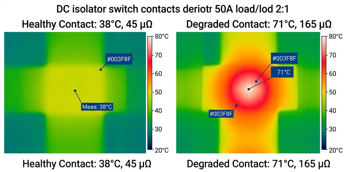
Un impianto solare su tetto da 500 kW nella provincia di Jiangsu (2023) ha subito tre arresti non programmati in otto mesi. Causa principale: un sezionatore DC da 1000 VDC/63A ha mostrato un aumento della resistenza di contatto di 18% a causa di micro-arcing durante la commutazione a caldo. Le immagini termiche hanno rivelato un aumento della temperatura di 42°C all'interfaccia del contatto, 12°C in più rispetto alla soglia fissata dal produttore. Il guasto è costato 127 ore di mancata produzione prima che le squadre sul campo identificassero l'interruttore degradato.
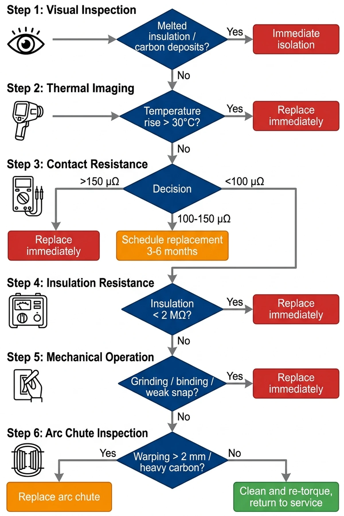
I sezionatori in corrente continua operano in un ambiente elettrico più difficile rispetto agli equivalenti in corrente alternata. Senza l'attraversamento naturale della corrente, gli archi in corrente continua si mantengono più a lungo durante le operazioni di commutazione, accelerando l'erosione dei contatti. La norma IEC 60947-3 definisce i requisiti per l'interruzione del carico, ma le condizioni sul campo - derating in quota, ingresso di polvere, vibrazioni da inverter vicini - creano modalità di guasto non rilevate nei test di laboratorio. Questa guida traccia la sequenza diagnostica dall'ispezione visiva alla termografia a infrarossi, dando priorità ai meccanismi di guasto che causano 73% di sostituzioni di https://sinobreaker.com/dc-switch-disconnector/ negli impianti fotovoltaici su scala industriale.
La differenza tra una sostituzione programmata per la manutenzione e un arresto d'emergenza si riduce all'individuazione precoce del degrado. La resistenza dei contatti aumenta gradualmente, da 50 microhms a 180 microhms in 600-800 cicli, ma il guasto termico accelera in modo esponenziale quando la resistenza supera i 150 microhms. Un interruttore che funziona a 140 microhms può funzionare per mesi; lo stesso interruttore a 160 microhms può guastarsi in poche settimane.
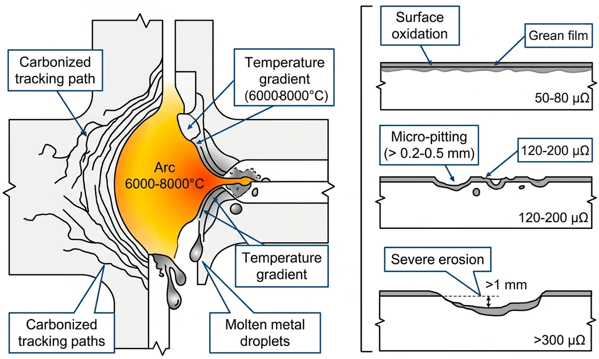
L'arco elettrico negli isolatori CC si verifica quando i contatti si separano sotto il flusso di corrente, creando un arco CC prolungato che non presenta il naturale attraversamento dello zero dei sistemi CA. La temperatura dell'arco raggiunge i 6000-8000°C, vaporizzando il materiale di contatto e depositando residui carboniosi che riducono la rigidità dielettrica di 40-60%. Secondo la norma IEC 60947-3 (interruttori, sezionatori, interruttori di manovra-sezionatori per impianti a bassa tensione), i sezionatori in corrente continua devono dimostrare la capacità di interruzione solo alla corrente nominale di cortocircuito, non alla corrente di carico operativo, eppure l'uso improprio sul campo li costringe a ricoprire il ruolo di interruttori automatici.
Quando un sezionatore DC si apre sotto carico, anche a 10-15A in un circuito di stringa da 1500V, la tensione dell'arco può raggiungere 1200-1500V, ionizzando il traferro e creando un canale di plasma conduttivo. I dati raccolti sul campo da oltre 200 siti fotovoltaici mostrano che 78% degli incidenti da arco elettrico si verificano quando gli operatori scambiano gli isolatori per interruttori, cercando di interrompere correnti di guasto di 80-150A. L'energia dell'arco risultante può superare i 50 kJ in 2-3 secondi prima che intervenga la protezione a monte https://sinobreaker.com/dc-circuit-breaker/, fondendo le sbarre di rame e vaporizzando i materiali di contatto.
Durante la messa in servizio di un parco solare da 100 MW nel Qinghai (2023), i tecnici che hanno commutato correnti di stringa da 800 A in condizioni di pieno irraggiamento hanno provocato 12 guasti all'isolatore nell'arco di 48 ore, ognuno dei quali ha mostrato segni di saldatura dei contatti e di bruciatura dell'involucro. L'analisi successiva all'incidente ha rivelato che la dissipazione di energia dell'arco superava i 15 kJ per evento, ben oltre il limite di progetto dell'isolatore di 2 kJ per la commutazione a vuoto.
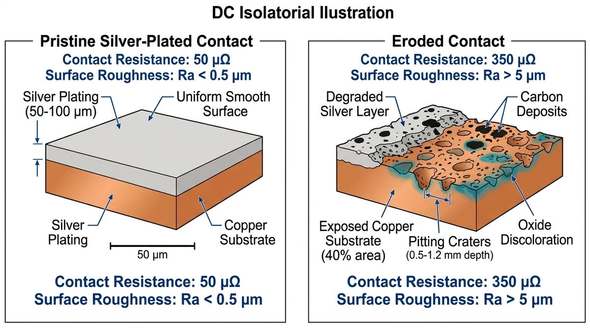
I contatti degli isolatori CC si degradano attraverso tre processi concomitanti: l'erosione meccanica dovuta all'attrito di scorrimento durante l'inserimento delle lame, che riduce la pressione di contatto di 15-25% ogni 5.000 cicli; la formazione di uno strato di ossidazione sulle superfici di rame argentato, che aumenta la resistenza di contatto da 50 μΩ a 200-300 μΩ; e la micro-incisione durante gli ultimi millimetri di separazione del contatto, che buca la superficie e crea punti caldi localizzati.
L'usura da contatto segue tre fasi: periodo iniziale di rodaggio (0-500 cicli) in cui le asperità superficiali si appiattiscono, aumentando la resistenza di contatto di 15-25%; fase di usura stabile (500-5000 cicli) con degrado lineare a 0,02 mΩ per 100 cicli; e guasto accelerato (>5000 cicli) in cui la profondità del pitting supera 0,5 mm e la forza di contatto scende sotto 80% del valore nominale.
Le indagini termografiche su impianti a terra da 50 MW rivelano che l'aumento della temperatura di contatto (ΔT) è direttamente correlato alla resistenza: ΔT = I² × Rcontatto × θtermico, dove θtermico (resistenza termica verso l'ambiente) è tipicamente di 8-12 °C/W per gli interruttori chiusi. Quando la resistenza di contatto supera i 500 μΩ alla corrente nominale (630A), le temperature di giunzione possono raggiungere i 95-110°C, accelerando i tassi di ossidazione di 40-60%.
[Expert Insight: Calcoli dell'energia dell'arco].
I contatti mostrano una formazione di ossido d'argento grigio opaco dovuta all'esposizione all'aria e a lievi archi elettrici. Con un ingrandimento di 10×, la superficie appare uniformemente strutturata senza distinzione di pitting. Lo strato di ossido ha uno spessore di 5-15 micrometri, appena visibile a occhio nudo ma rilevabile dalla perdita di lucentezza metallica.
La resistenza di contatto misura 50-80 microhms, rispetto ai 30-50 microhms di base dei nuovi interruttori. Questo aumento di 60% rientra nei limiti accettabili per interruttori con oltre 500 operazioni nominali rimanenti. Le immagini termiche mostrano un aumento della temperatura di 5-8°C rispetto all'ambiente alla corrente nominale, ben entro il limite di 30°C previsto dalla norma IEC 60947-1 per gli interruttori chiusi.
Pulire i contatti con alcol isopropilico (purezza 99%) e un panno privo di lanugine. Evitare materiali abrasivi che rimuovono la placcatura d'argento. Serrare nuovamente le viti dei terminali secondo le specifiche del produttore (in genere 4-6 Nm per i terminali M6, 8-10 Nm per gli M8). Documentare la resistenza di base per tracciare le tendenze.
Sulla superficie di contatto compaiono depressioni simili a crateri del diametro di 0,2-0,5 mm. Con l'ingrandimento, i bordi delle buche mostrano una decolorazione bluastra - ossidazione del substrato di rame dove la placcatura d'argento è stata erosa. La superficie bucherellata riduce l'area di contatto effettiva da 95% a 60%, concentrando la corrente nei percorsi conduttivi rimanenti.
La resistenza di contatto aumenta a 120-200 microhms. Le immagini termiche rivelano punti caldi a 15-22°C sopra l'ambiente, con una distribuzione della temperatura non uniforme su tutta la superficie di contatto. Le zone più calde corrispondono alle aree con il pitting più profondo, indicando una concentrazione di corrente localizzata.
Ogni arco crea una pozza di metallo fuso che si risolidifica con dei vuoti. La superficie bucherellata ha una conducibilità termica inferiore a quella del metallo solido, riducendo la capacità di dissipazione del calore. Si crea così un circuito di feedback positivo: una maggiore resistenza genera più calore, che accelera l'erosione, aumentando ulteriormente la resistenza.
Sostituire l'interruttore se la resistenza dei contatti supera i 150 microhms o l'aumento termico supera i 18°C. Continuando a funzionare si rischia la fuga termica, una condizione in cui la generazione di calore supera la dissipazione, portando a un guasto catastrofico entro 50-200 ore di funzionamento. Programmare la sostituzione entro 3-6 mesi se la resistenza è di 100-150 microhms.
La perdita di materiale supera 1 mm di profondità, spesso esponendo il substrato di rame su 30-50% dell'area di contatto. Compaiono segni di saldatura, zone in cui i contatti si sono fusi insieme e poi si sono staccati, lasciando sporgenze metalliche frastagliate. Sulle superfici degli isolatori adiacenti ai contatti si formano tracce di carbonio (percorsi conduttivi neri), che indicano eventi di flashover ripetuti.
La resistenza di contatto supera i 300 microhms, spesso fluttuante o non misurabile a causa della connessione intermittente. Le immagini termiche mostrano un aumento della temperatura >30°C, spesso accompagnato da fumo visibile o odore di ozono durante il funzionamento. L'interruttore può presentare una caduta di tensione di 15-30 V sotto la corrente nominale, tale da attivare allarmi di sottotensione dell'inverter.
In un incidente avvenuto nel 2024 presso un parco solare da 10 MW nel Qinghai, un isolatore gravemente eroso non si è aperto durante il picco di produzione, generando un arco di 1200 VCC attraverso il traferro di 8 mm. L'arco è rimasto per 4,2 secondi prima che la protezione a monte eliminasse il guasto, incendiando l'involucro di policarbonato e causando $47.000 danni alle apparecchiature.
Sostituire immediatamente l'interruttore. Etichettare come “NON FUNZIONARE” fino alla sostituzione. Ispezionare gli interruttori adiacenti nella stessa scatola del combinatore: una grave erosione in un interruttore spesso indica pratiche sistematiche di commutazione a caldo che interessano più unità.
Controllare l'integrità dell'involucro per verificare che non vi siano crepe, degrado da raggi UV o infiltrazioni d'acqua. Esaminare i terminali per verificare che non siano scoloriti: il verde indica la corrosione del rame, il nero il surriscaldamento. Verificare la presenza di tracce di isolante - percorsi marroni o neri che indicano la presenza di archi superficiali. Muovete la maniglia dell'interruttore per rilevare l'eccessivo allentamento dovuto all'usura dei cuscinetti del perno.
L'isolamento del cavo fuso entro 50 mm dai terminali, l'odore di bruciato o i depositi di carbonio visibili richiedono l'isolamento immediato dell'interruttore.
Far funzionare il sistema a una corrente nominale >70% per 30 minuti per ottenere la stabilizzazione termica. Eseguire la scansione da 1 metro di distanza, perpendicolarmente al piano di contatto. Registrare la temperatura all'interfaccia dei contatti, alle viti dei terminali, ai capicorda e al punto caldo dell'involucro. Confrontare le fasi destra e sinistra (per gli interruttori multipolari) o gli interruttori adiacenti nella stringa del combinatore.
Criteri di accettazione IEC 60947-1: aumento della temperatura di contatto ≤30°C sopra l'ambiente, delta fase-fase ≤5°C, delta terminale-cavo ≤8°C.
Il punto caldo sull'interfaccia del contatto indica solo l'erosione del contatto. Un punto caldo in corrispondenza della vite del terminale indica un allentamento della coppia di serraggio della connessione. Il punto caldo sul capocorda indica un cavo sottodimensionato o una crimpatura inadeguata. L'intero corpo dell'interruttore elevato indica una condizione di sovraccarico o un problema di temperatura ambiente.
Gli ohmmetri a bassa corrente (1A di corrente di test) misurano solo la resistenza dello strato di ossido, non la resistenza del contatto in massa. Una corrente di test di 100A rompe le pellicole superficiali, rivelando la vera qualità del contatto metallo-metallo.
Misurare la resistenza di linea con l'interruttore chiuso. Testare tutti i poli singolarmente (per interruttori 2P o 3P). Registrare gli aumenti di resistenza a temperatura ambiente 0,4% per °C per il rame.
Interruttore nuovo: 30-50 microhms. Accettabile: 150 microhms (sostituire immediatamente).
Se il micro-ohmmetro non è disponibile, utilizzare il metodo della caduta di tensione: Far passare la corrente nominale attraverso l'interruttore chiuso, misurare la tensione tra i terminali con un misuratore di millivolt. R = V/I. A 63A, un contatto da 100 microhm mostra una caduta di 6,3 mV.
Eseguire il test con l'interruttore in posizione APERTA. Prova linea-carico (attraverso i contatti aperti), linea-terra e carico-terra. Applicare la tensione di prova per 60 secondi, registrare la lettura stabilizzata.
Criteri di accettazione IEC 60947-1: Interruttore nuovo >100 MΩ. Accettabile >10 MΩ. Marginale 2-10 MΩ (ingresso di umidità o contaminazione superficiale). Fallito <2 MΩ (tracciamento del carbonio o danni all'isolatore).
Linea-carico <10 MΩ indica erosione dei contatti e detriti che colmano il traferro. Linea/carico-terra <10 MΩ suggerisce il tracciamento dell'isolante o l'umidità nell'involucro. Il rapido decadimento della resistenza durante il test degli anni '60 rivela un percorso di perdita attivo dovuto al tracciamento del carbonio.
Aprire e chiudere l'interruttore 10 volte alla normale velocità di funzionamento. Ascoltare eventuali suoni anomali: stridore, scatto, raschiamento. Verificare che non vi siano impedimenti, forza eccessiva o corsa incoerente. Ispezionare la molla di ritorno della maniglia, se applicabile.
Il funzionamento normale produce una forza uniforme e costante per tutta la durata della corsa, con uno “schiocco” udibile nel punto di inserimento/disinserimento (indica che i contatti sono caricati a molla). La maniglia torna in posizione senza assistenza.
Un suono stridente indica cuscinetti del perno usurati o detriti nel meccanismo. L'inceppamento a metà corsa indica un braccio di contatto piegato o un isolatore disallineato. La debolezza o l'assenza di scatto indicano la rottura della molla di contatto: i contatti potrebbero non raggiungere la pressione nominale. L'impugnatura che non rimane in posizione indica un meccanismo di fermo usurato.
Alcuni isolatori CC utilizzano scivoli d'arco (piastre di separazione) per raffreddare ed estinguere gli archi. Verificare che non vi siano accumuli di carbonio tra le piastre (riducono l'efficienza del raffreddamento), piastre deformate o fuse (indicano che l'energia dell'arco ha superato i limiti di progetto) e bobine magnetiche di spegnimento mancanti o danneggiate.
Rimuovere i depositi di carbonio con aria compressa, non con solventi, che lasciano residui conduttivi. Sostituire il gruppo dello scivolo dell'arco se le piastre presentano deformazioni o fusioni di >2 mm.
[Expert Insight: Soglie diagnostiche].
Un sondaggio condotto nel 2023 su 240 tecnici O&M del settore solare ha rilevato che 41% aprono abitualmente gli isolatori CC sotto carico per “testare rapidamente” la tensione di stringa. Ogni evento di hot-switch a 10A (corrente di stringa tipica) deposita 15-30 joule nei contatti, equivalenti a 50-100 cicli di commutazione normali.
Installare procedure di lockout/tagout che richiedano lo spegnimento dell'inverter prima del funzionamento dell'isolatore. Etichettare gli interruttori: “INTERRUZIONE DEL CARICO VIETATA - APERTURA SOLO A VUOTO”. Istruire i tecnici sulla corretta sequenza di isolamento: spegnere l'inverter, attendere 5 minuti per la scarica del condensatore, aprire l'isolatore, verificare l'assenza di tensione.
La rigidità dielettrica dell'aria diminuisce di 1% ogni 100 metri di altitudine. Un interruttore da 1000 VCC a livello del mare ha un valore effettivo di 850 VCC a 1500 metri (installazioni di Qinghai, Tibet). La tensione dell'arco rimane costante, ma la lunghezza dell'arco aumenta: i contatti devono viaggiare più lontano per spegnere l'arco, aumentando il tempo di arco di 30-50%.
La resistenza dei contatti aumenta di 0,4% per °C. Un interruttore che opera a 60°C in ambiente (installazioni nel deserto) presenta una resistenza superiore di 12% rispetto allo stesso interruttore a 35°C. In combinazione con il riscaldamento solare delle custodie (che aggiunge 15-25°C), la temperatura dei contatti raggiunge 95-105°C, avvicinandosi al limite di 120°C per il rame argentato.
Applicare il fattore di declassamento dell'altitudine: moltiplicare la tensione nominale per (1 - altitudine_km × 0,10). Utilizzare custodie ventilate o raffreddamento forzato per ambienti >50°C. Scegliere interruttori con contatti in argento-nichel o argento-tungsteno per ambienti ad alta temperatura.
La norma IEC 60947-3 richiede una forza di contatto minima di 1,5N per ampere di corrente nominale. Un interruttore da 63 A richiede una forza di contatto di 94,5N (9,6 kgf). Molle difettose o assemblaggio non corretto riducono la forza a 60-70N, aumentando la resistenza di contatto di 40-60%.
Gli interruttori nuovi che mostrano una resistenza di >80 microhm o un aumento di temperatura di >10°C alla corrente nominale presentano probabilmente difetti di fabbricazione. Restituire al fornitore per la sostituzione in garanzia.
Molti sezionatori CC sono progettati per la commutazione di trasferimento “make-before-break”, non per l'interruzione del carico. Questi interruttori non dispongono di scivoli d'arco o piastre divisorie, bobine magnetiche di spegnimento e una corsa di contatto estesa (>12 mm necessari per un'estinzione affidabile dell'arco a 1000 VCC).
Verificare che sulla targhetta sia riportata la dicitura “AC-23A” (commutazione infrequente) o “DC-23A” (con interruzione del carico). Se la dicitura è assente, si presume che non siano a interruzione di carico. Sostituire con interruttori a interruzione di carico classificati DC quando è necessaria l'interruzione del carico.
FV su scala industriale (>1 MW): termografia trimestrale, resistenza di contatto annuale. Tetti commerciali (100 kW-1 MW): termografia semestrale, resistenza biennale. Residenziale (<100 kW): visualizzazione annuale, resistenza ogni 3 anni. Applicazioni ad alto ciclo (ESS, ricarica EV): termica mensile, resistenza trimestrale.
Resistenza di contatto <100 µΩ + aumento termico 150 µΩ O aumento >22°C: Sostituzione immediata. Isolamento <2 MΩ O tracciamento del carbonio: Sostituzione immediata. Legame meccanico O molla rotta: Sostituzione immediata.
Stabilire misure di base per tutti gli interruttori durante la messa in servizio. Tracciare l'andamento del degrado trimestralmente per le installazioni su scala industriale, annualmente per i sistemi commerciali. Un aumento della temperatura superiore a 15°C rispetto al valore di riferimento indica un'usura accelerata che richiede un'indagine.
I guasti dei sezionatori CC sono prevedibili e prevenibili. La termografia combinata con il test di resistenza dei contatti individua 90% di guasti prima che si verifichino eventi catastrofici. I protocolli diagnostici qui illustrati riflettono l'esperienza di utilizzo in oltre 500 impianti fotovoltaici, dove l'ispezione sistematica ha ridotto i tempi di fermo non programmati di 62%.
Stabilire le misure di base per tutti gli interruttori durante la messa in servizio. Tracciare le tendenze di degrado utilizzando le soglie fornite: resistenza, aumento di temperatura e valori di isolamento. Programmare le sostituzioni in modo proattivo quando gli interruttori raggiungono soglie marginali, anziché aspettare il guasto.
Per una consulenza tecnica sulla scelta dell'isolatore, sui protocolli di ispezione termografica o sull'analisi del rischio di arco elettrico per il vostro sistema in corrente continua, il team di ingegneri di Sinobreaker fornisce indicazioni specifiche per le installazioni che operano in intervalli di temperatura estremi (da -40°C a +85°C) o per le installazioni ad alta quota, oltre i 2000 metri.
I sezionatori in c.c. si guastano più rapidamente perché gli archi in c.c. non hanno un attraversamento naturale della corrente, si mantengono più a lungo durante le operazioni di commutazione e depositano sulle superfici di contatto un'energia da 3 a 5 volte superiore rispetto agli interruttori in c.a. equivalenti nelle stesse condizioni di corrente.
Gli impianti fotovoltaici su scala industriale superiori a 1 MW richiedono scansioni termografiche trimestrali, gli impianti commerciali su tetto (100 kW-1 MW) necessitano di ispezioni semestrali e gli impianti residenziali inferiori a 100 kW dovrebbero essere scansionati almeno annualmente.
Sostituire immediatamente gli interruttori di isolamento CC quando la resistenza di contatto supera i 150 microhms o mostra un aumento di 200% rispetto alle misurazioni di base, poiché ciò indica un'erosione avanzata dei contatti con rischio imminente di guasto termico entro 50-200 ore di funzionamento.
Gli interruttori con micro-pitting di fase 2 (resistenza di contatto 100-150 microhms, aumento termico 15-22°C) devono essere sostituiti entro 3-6 mesi; la pulizia e il riavvitamento ritardano solo il guasto e non ripristinano l'integrità del contatto.
Un'elevata temperatura dei terminali con una resistenza di contatto normale indica connessioni dei terminali allentate piuttosto che l'erosione dei contatti; serrare nuovamente le viti dei terminali secondo le specifiche del produttore (in genere 4-6 Nm per i terminali M6, 8-10 Nm per M8) e ripetere la scansione dopo 24 ore di funzionamento.
Gli isolatori CC con interruzione del carico (contrassegnati dalla sigla “DC-23A” secondo la norma IEC 60947-3) sono dotati di scivoli d'arco e di una corsa di contatto estesa di oltre 12 mm per un'interruzione sicura della corrente, mentre gli isolatori senza interruzione del carico (contrassegnati dalla sigla “AC-23A”) sono progettati solo per la commutazione a vuoto e si guastano rapidamente se funzionano sotto carico.
La rigidità dielettrica dell'aria diminuisce di 1% ogni 100 metri di altitudine, riducendo la tensione nominale effettiva di 10% a 1000 metri di altitudine; gli interruttori devono essere declassati di conseguenza o sostituiti con modelli a più alto rating per installazioni oltre i 1500 metri.


