Indirizzo
304 Nord Cardinale
St. Dorchester Center, MA 02124
Orario di lavoro
Da lunedì a venerdì: dalle 7.00 alle 19.00
Fine settimana: 10.00 - 17.00
Indirizzo
304 Nord Cardinale
St. Dorchester Center, MA 02124
Orario di lavoro
Da lunedì a venerdì: dalle 7.00 alle 19.00
Fine settimana: 10.00 - 17.00

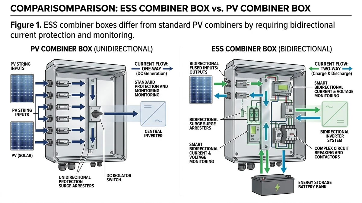
Before you size protection or order hardware, it helps to separate ESS combiner duties from the PV-only logic many engineers already know.
An ESS combiner box differs from a standard PV combiner in one critical way: current flows in both directions. During charging, power moves from the grid or PV array into the battery; during discharge, it reverses. Standard PV combiners are designed for unidirectional current only, making them unsuitable for battery array protection without significant redesign.
A conventional Scatola combinatore FV uses gPV string fuses and blocking diodes optimized for one-way current flow from panels to inverter. In an ESS application, those same fuses must interrupt fault current arriving from either direction — a condition that can cause asymmetric arc behavior and premature fuse failure if the device isn’t rated accordingly.
IEC 60269-6 governs gPV fuse performance under PV-specific conditions, but ESS applications introduce bidirectional fault scenarios that push beyond its original scope. For battery arrays operating at 800–1500 VDC bus voltage, prospective short-circuit current at the DC busbar commonly reaches 20–40 kA, significantly higher than typical string-level PV fault currents of 2–3× Isc.
A 20 MWh lithium-ion ESS project in Guangdong (2024) required protection devices rated for bidirectional 150 kA fault current. Conventional MCBs failed pre-qualification testing, and the design team ultimately specified DC molded case circuit breakers with verified bidirectional breaking capacity.
For deeper context on protection selection in storage systems, the ESS battery storage protection guide covers fault current coordination in detail.
| Parametro | Standard PV Combiner | ESS Combiner Box |
|---|---|---|
| Current direction | Unidirectional (PV → inverter) | Bidirectional (charge + discharge) |
| Typical bus voltage | 600–1500 VDC | 48–1500 VDC |
| Fault current source | PV string Isc (typically 10–20 A/string) | Battery bank (20–40 kA prospective) |
| Protection device type | gPV string fuses + blocking diodes | Bidirectional DC MCB or MCCB |
| Protezione dalle sovratensioni | Optional (lightning zones) | Mandatory (switching transients) |
| Monitoraggio | String current monitoring | SOC, voltage, temperature, current |
| Applicable standard | IEC 62548-1, IEC 60269-6 | IEC 62619, IEC 60947-2 |
Once current can reverse, fault behavior changes from a panel-limited event to a low-impedance battery event that demands faster and tougher protection.
In a battery ESS array, fault current behavior is fundamentally different from a PV source, and that difference drives every protection decision in a combiner box. Unlike solar strings that are current-limited by irradiance, lithium iron phosphate (LFP) battery cells behave as near-ideal voltage sources under fault conditions, capable of delivering fault currents that rise faster and sustain longer than many protection engineers expect.
LFP cells have exceptionally low internal impedance — typically 0.5–2 mΩ per cell at operating temperature. In a 16S battery module (nominal 51.2 V), a bolted short-circuit at the module terminals can drive fault current from zero to peak in under 2 milliseconds. Scale that to a rack-level 48 V or 100 V bus with parallel strings, and prospective short-circuit current at the DC busbar commonly reaches 20–50 kA depending on string count and cable impedance. IEC 62619 requires that protection devices respond within this rise-time window — a constraint that eliminates many conventional MCB designs from consideration.
A 20 MWh LFP-based ESS project in Guangdong (2024) reportedly required protection devices rated for bidirectional fault current exceeding 150 kA because standard MCB magnetic trip units could not respond fast enough to the sub-millisecond current ramp.
Extinguishing a DC arc in a battery array is harder than in a PV system because the source voltage does not collapse during the fault. A PV string voltage sags as current rises; a battery holds its terminal voltage nearly constant throughout the event. That means arc voltage must be driven above system voltage entirely through arc elongation and resistance insertion within the DC breaker or fuse element, with no help from source impedance.
For a 100V battery bus, the arc extinction condition requires the protective device to develop an arc voltage Varc ≥ Vbus + Vmargin, where Vmargin is typically 10–20% above nominal. At 1000 VDC bus configurations used in larger ESS racks, this demands arc chute designs generating field strengths of 80–150 mT to achieve sufficient arc elongation within the breaker’s interrupting chamber.
The most dangerous fault mode in a parallel battery array is often a cross-string fault, where one healthy string back-feeds into a faulted adjacent string. Fault current flows from healthy strings through the combiner bus, into the fault point, and returns through the faulted string’s internal path. Without per-string DC fuse or breaker protection, all parallel strings contribute simultaneously, and total fault energy can exceed the thermal withstand of unprotected busbars in under 100 ms. This is why string-level protection belongs inside the ESS combiner box, not only at the inverter input.
According to the IEC TC21 working group on stationary battery safety, cross-string fault energy in parallel LFP arrays is a primary driver behind the move toward current-limiting fuse elements rated specifically for battery discharge duty rather than standard PV-only assumptions.
[Expert Insight]
– Put current sensors on both the common bus and each string; cross-string faults are easier to detect from imbalance than from absolute current alone.
– In parallel racks, keep string cable lengths closely matched so one path does not become the preferred fault-return route.
– Review busbar short-time withstand against the fuse clearing time, not only against nominal current.
With the fault physics clear, the next step is choosing devices that can isolate a single string before the whole rack contributes energy to the event.
Selecting string-level protection for an ESS combiner comes down to two variables: system voltage class and maximum prospective short-circuit current at the point of protection.
Two device categories dominate string-level protection in ESS combiner boxes.
gPV fuses remain a common option for overcurrent protection on individual DC strings. Rated to IEC 60269-6, they are designed for photovoltaic DC circuits and are also used in some ESS architectures where current-limiting behavior is required. A gPV fuse will carry 1.35 × In continuously without degradation, which matters in high-ambient combiner enclosures.
DC MCBs and MCCBs add switching capability alongside protection, making them the preferred choice where string isolation for maintenance is a regular requirement. IEC 60947-2 governs their breaking capacity (Icu) and service breaking capacity (Ics), and both should be checked against prospective fault current at the busbar, not just the string operating current.
| ESS Voltage Class | Typical String Voc | Recommended Fuse Rating | DC Breaker Voltage Rating | Min. Breaking Capacity |
|---|---|---|---|---|
| 48 V | 40–60 V | 15–30 A / 100 VDC | 63 VDC MCB | 3 kA |
| 400 V | 350–450 V | 10–20 A / 500 VDC | 500 VDC MCB | 6 kA |
| 800 V | 700–900 V | 10–15 A / 1000 VDC | 1000 VDC MCCB | 10 kA |
| 1000 V | 900–1100 V | 10–15 A / 1200 VDC | 1000 VDC MCCB | 15 kA |
A 20 MWh lithium-ion ESS project in Zhejiang Province (2023) used 800 V battery arrays with 12-string combiner boxes. Each string delivered a short-circuit current (Isc) of 11 A at STC.
Per IEC 60269-6 sizing rules, the fuse rated current (In) must satisfy:
Result: a 15 A / 1000 VDC gPV fuse satisfies both the continuous carry requirement and the fault-detection window. The project’s commissioning report noted zero nuisance fuse operations during the first 12 months of operation, largely because the team followed the 1.25× lower bound instead of rounding down to a 10 A device.
For a broader view of string-to-busbar topology, the PV combiner box single-line diagram design guide is a useful reference.
Protection in the field is not a single device decision; it is a sequence, and thermal events show quickly whether that sequence is coordinated.
When a lithium-ion battery cell enters thermal runaway inside an ESS rack, the combiner box and associated controls must respond in order: BMS signal, string isolation, fuse backup, then SPD clamp. Each layer has a distinct job, and a gap in any one of them can let fault energy spread across the array.
The Battery Management System is the first detection layer. It continuously monitors cell voltage, temperature, and state of charge. When cell temperature exceeds a threshold — typically 60–80°C depending on chemistry — or voltage deviation crosses about ±150 mV from the pack mean, the BMS issues a trip signal within 10–50 ms.
On receiving the BMS trip signal, the string-level DC switch disconnector or DC breaker opens to isolate the affected string from the common DC bus. In a 20 MWh lithium-ion ESS project in Zhejiang Province (2023), string-level isolation prevented sustained fault currents above 200 A from reaching the busbar. The disconnector must be rated for the full DC bus voltage and capable of breaking load current without re-strike.
If the disconnector fails to open, or fault current rises faster than the BMS can react, the gPV fuse serves as the passive backup. Sized to IEC 60269-6, it limits let-through energy and interrupts high fault current without needing a control signal.
Thermal runaway events and rapid fault interruptions both generate high-energy transients on the DC bus. A surge protection device rated to IEC 61643-31 clamps these transients before they reach inverter and BMS electronics. The SPD protection level (Up) should sit below the impulse withstand of the connected equipment, typically Up ≤ 2.5 kV for 1000 VDC systems.
This four-step sequence — detect, isolate, interrupt, clamp — is what separates a contained cell event from a full rack failure.
[Expert Insight]
– Test the BMS trip output and the breaker opening command as one functional chain; a good BMS alarm is useless if the isolation device does not actuate.
– Set event logs to capture pre-fault current and temperature trends for at least several seconds before trip; it shortens root-cause analysis after commissioning.
– Verify SPD status indication during maintenance rounds, because a spent SPD often remains physically installed but no longer protects.
Even a well-specified combiner can underperform if the field installation treats ESS conductors like ordinary PV strings.
ESS rack wiring introduces installation challenges that standard PV combiner design does not fully anticipate. Battery arrays push and pull current through the same conductors, and that bidirectional profile changes how you size cables, busbars, and protective devices.
Follow these steps before energizing any ESS rack combiner:
Bidirectional current does not change Ohm’s law, but it does change thermal accumulation. Cables that cool during one operating window may not fully recover before the next discharge peak, reducing practical thermal margin.
For ESS bus bar sizing, apply a derating factor of 0.8× the standard DC ampacity table value when continuous bidirectional cycling exceeds 1C. For copper bus bar at 35°C ambient, a 40 mm × 5 mm cross-section carries approximately 320 A unidirectional — derated to ~256 A for sustained ESS cycling duty.
A 20 MWh lithium-ion ESS project in Zhejiang Province (2024) found that busbar joints originally specified for unidirectional PV duty reached junction temperatures 28°C above ambient during peak grid-export cycles, triggering nuisance trips on the DC circuit breaker protection. Upsizing busbar cross-section by 25% solved the issue without replacing protective devices.
Locking the critical specifications before purchase is the most practical way to avoid redesign, replacement, and failed FAT testing.
| # | Parametro | What to Specify | Typical ESS Range |
|---|---|---|---|
| 1 | System Voltage Rating | Max DC operating voltage | 600–1500 VDC |
| 2 | String Fuse Rating | gPV fuse current rating per IEC 60269-6 | 10–32 A per string |
| 3 | Short-Circuit Breaking Capacity | Icu at rated voltage | 20–50 kA |
| 4 | Number of Input Strings | Matched to battery rack count | 4–16 strings |
| 5 | Bidirectional Current Support | Charge and discharge fault protection | Required for ESS |
| 6 | SPD Protection Level (Up) | Per IEC 61643-11, Type II minimum | ≤2.5 kV at 1000 VDC |
| 7 | Enclosure IP Rating | Ingress protection for installation environment | IP54 (indoor) / IP65 (outdoor) |
| 8 | Monitoring Output | String-level current monitoring, RS485/Modbus | Facoltativo ma consigliato |
Parameters 3 and 6 are the most commonly under-specified in field orders. A 20 MWh lithium-ion ESS project in Zhejiang (2024) had to replace an entire combiner box batch because the original units were rated for only 10 kA breaking capacity, well below the 35 kA prospective fault current measured at the DC busbar.
Cross-check gPV fuse ratings against the battery manufacturer’s maximum reverse current specification, and align the DC switch disconnector selection with the site’s maintenance isolation procedure. If you are still finalizing the wider architecture, the ESS battery storage protection guide and the PV combiner box design series are the best next references.
An ESS combiner must handle bidirectional current, higher battery-driven fault energy, and coordination with BMS and storage protection devices, not just PV string aggregation.
Not without major redesign. Standard PV combiners are typically built around one-way current assumptions and may not have the right interrupting ratings for battery faults.
Because fault current can arrive from either the charging side or the discharging battery side. If the protective device is only qualified one way, arc interruption may be unreliable.
Start with the string current and voltage, then verify the fuse current window and voltage rating against the applicable standard and the actual maximum DC bus conditions.
In practice, they should be treated as essential. Switching events and fast fault clearing can create transients that threaten BMS, inverter, and control electronics.
Incorrect assumptions carried over from PV projects are a major cause, especially undersized busbars, inadequate breaking capacity, and untested bidirectional isolation devices.
Many designs fall in the 4 to 16 string range, but the right count depends on bus current, protection coordination, enclosure heat rise, and maintenance requirements.