Indirizzo
304 Nord Cardinale
St. Dorchester Center, MA 02124
Orario di lavoro
Da lunedì a venerdì: dalle 7.00 alle 19.00
Fine settimana: 10.00 - 17.00
Indirizzo
304 Nord Cardinale
St. Dorchester Center, MA 02124
Orario di lavoro
Da lunedì a venerdì: dalle 7.00 alle 19.00
Fine settimana: 10.00 - 17.00

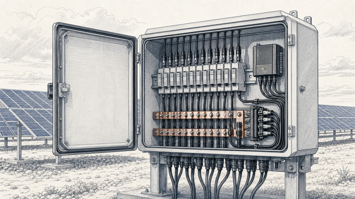
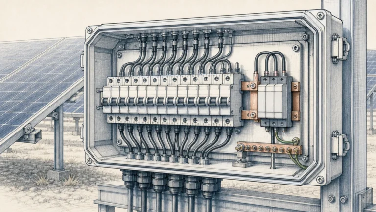
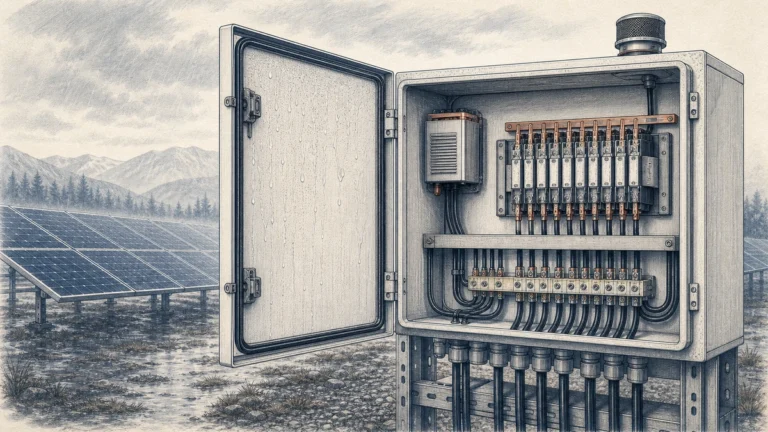
PV combiner box string monitoring gives plant owners and O&M teams visibility into the DC side of a solar PV array before power reaches the inverter. In a Sinobreaker PV Combiner Box, string monitoring can be configured to supervise individual string current, string voltage, surge protection device status, fuse or breaker status, and communication health.
For utility-scale and commercial PV systems, this monitoring is not only useful for daily operation. It also supports commissioning, troubleshooting, targeted maintenance, and long-term performance control. When alarm points are set correctly, pv combiner box string monitoring can help identify conditions such as blown fuses, damaged connectors, abnormal string mismatch, degraded modules, open circuits, and protection device failures.
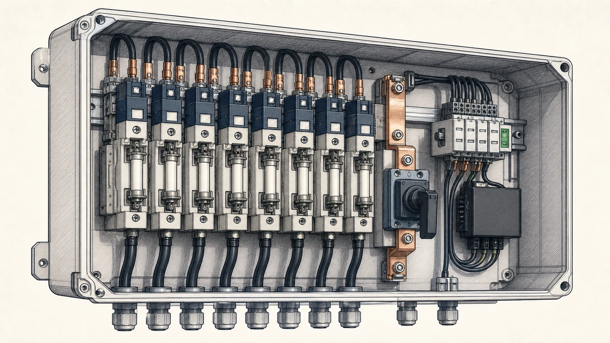
A PV combiner box collects multiple PV strings and combines them into one or more DC outputs. Without string-level monitoring, many DC-side problems may remain hidden until inverter production drops significantly or a manual inspection is performed.
With pv combiner box string monitoring, each string can be checked against expected operating behavior. This allows operators to detect abnormal current, voltage deviation, missing string output, or protection device status changes earlier.
A monitoring-enabled Sinobreaker PV Combiner Box may monitor:
These signals help the operator distinguish between production variation caused by weather and production loss caused by a physical fault.
Alarm points define when the monitoring system should report a warning or fault. If alarm thresholds are too sensitive, the system may generate nuisance alarms during normal irradiance changes. If thresholds are too loose, real faults may go unnoticed.
A practical alarm strategy should consider:
The goal is not to alarm on every small variation. The goal is to detect abnormal conditions that require investigation.
Alarm settings should be confirmed during engineering design and adjusted after commissioning data is available. The values below are practical categories to include in a monitoring plan, not universal setpoints for every project.
A low string current alarm is one of the most important functions of pv combiner box string monitoring. It can indicate that a string is underperforming or disconnected.
Possible causes include:
A low current alarm is usually more reliable when strings connected to the same combiner box are compared with each other under similar irradiance.
A zero current alarm should be treated as a higher priority than a general low current alarm. If one string shows zero current while neighboring strings are producing normally, the issue is likely physical or protection-related.
Typical inspection points include:
This alarm helps maintenance teams focus on the exact string instead of searching the entire array.
A high current alarm may occur if the measured value exceeds the expected operating range. Although PV string current is limited by module behavior, abnormal readings should still be checked.
Possible causes include:
During commissioning, high current alarm behavior should be verified against measured clamp meter readings where safe and practical.
Current imbalance alarms compare strings within the same combiner box or MPPT group. This is often more useful than using a fixed current threshold because irradiance changes affect all nearby strings.
A typical imbalance logic may compare each string against the group average. If one string remains significantly below the average for a defined time delay, an alarm is generated.
Important considerations include:
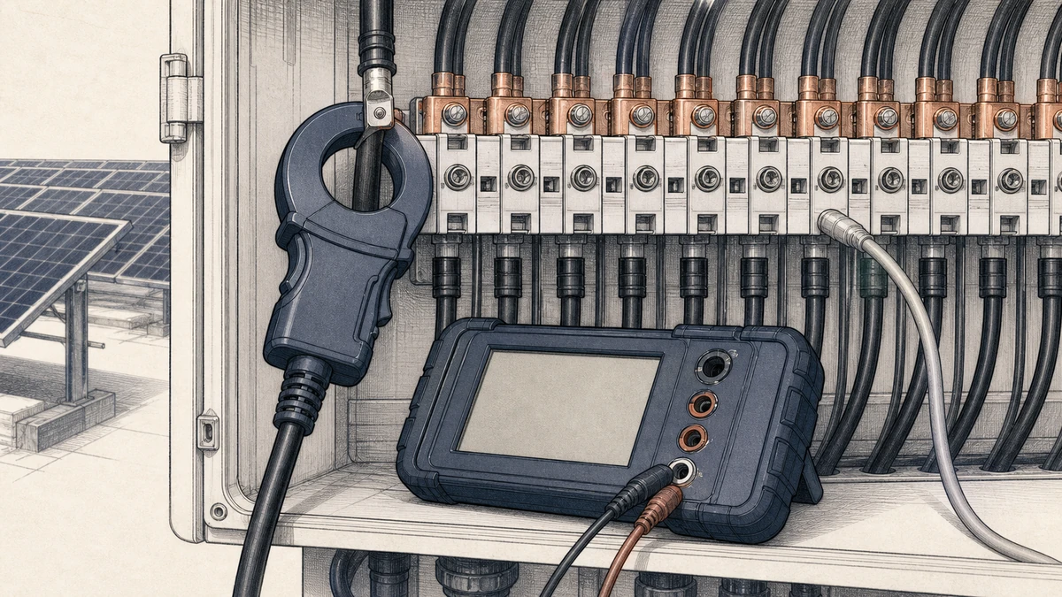
A low voltage alarm may indicate an open circuit, incorrect string length, severe module mismatch, or wiring error. Voltage alarms are especially useful during commissioning because they can reveal installation mistakes before full operation.
Potential causes include:
Voltage should be evaluated against expected values based on module data, string length, and cell temperature.
A high voltage alarm protects against unsafe or non-compliant operating conditions. PV string voltage rises in cold weather, so the maximum expected open-circuit voltage must be calculated during design.
A high voltage alarm may indicate:
The alarm threshold should be coordinated with the maximum DC voltage rating of the Sinobreaker PV Combiner Box, inverter, fuses, surge protection devices, and cable insulation.
Surge protection devices are critical for protecting DC equipment from transient overvoltage. A monitored SPD status contact allows the system to report when the SPD module needs inspection or replacement.
An SPD alarm may indicate:
During commissioning, the SPD status signal should be checked in both normal and alarm simulation conditions if the device design allows safe testing.
A DC breaker or switch status alarm confirms whether the combiner output protection device is open or closed. This is important for both operations and safety.
The monitoring system should clearly distinguish between:
If the PV combiner box includes a main DC breaker, the status signal should match the physical handle position during commissioning checks.
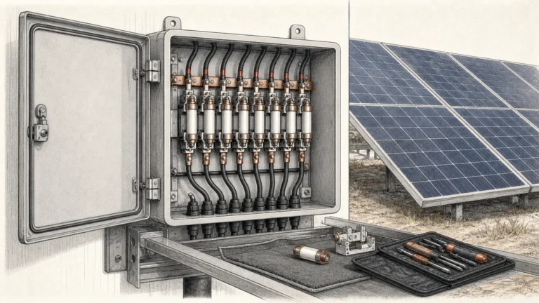
Where fuse monitoring is provided, a fuse status alarm can identify a blown fuse quickly. This is useful because a single blown fuse may reduce production without causing a full inverter shutdown.
Fuse alarm checks should confirm:
Monitoring data is only useful if it reaches the plant control system reliably. Communication alarms should be included for the combiner box monitoring module, data logger, and network path.
Common communication checks include:
A communication fault should not be confused with a string fault. The system should make it clear whether the problem is electrical production or data transmission.
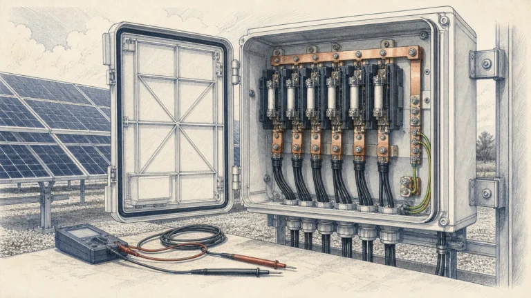
IEC 62446-1 covers documentation, inspection, and commissioning tests for grid-connected PV systems. For a Sinobreaker PV Combiner Box with string monitoring, commissioning should verify both the power circuit and the monitoring circuit.
Before field testing, confirm that the installation matches the approved design documents.
Check:
Any mismatch between the drawing and the installed system should be corrected or recorded before energization.
A visual inspection helps identify installation issues that electrical tests may not fully reveal.
Inspect:
The PV combiner box should be clean, dry, correctly labeled, and mechanically secure before testing continues.
Incorrect polarity is a serious DC-side risk. Each string input should be checked before connection or energization according to the project test procedure.
Verify:
These checks help prevent equipment damage and unsafe energization.
String open-circuit voltage should be measured and compared with expected design values. Differences may indicate incorrect module count, wiring errors, or damaged components.
Record:
The recorded values become a useful baseline for future troubleshooting.
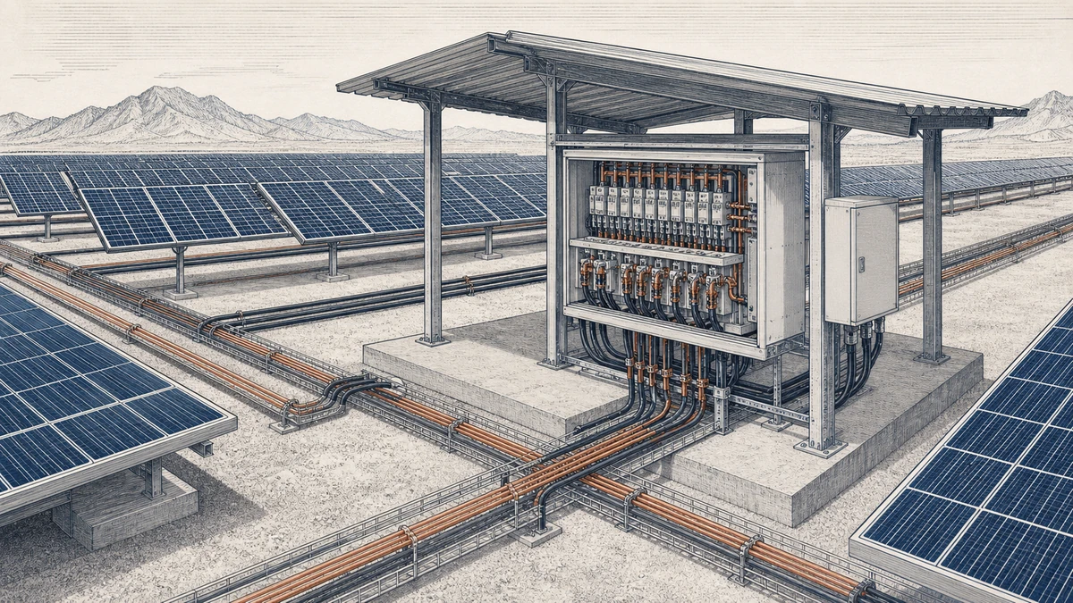
Insulation resistance testing helps confirm that DC cables, modules, and connections are not leaking current to earth. The test should be performed using suitable equipment and according to the applicable standard, project method statement, and component voltage ratings.
The test record should include:
Do not connect sensitive monitoring electronics to test voltages unless the equipment documentation confirms it is safe.
Loose DC terminals can cause overheating, voltage drop, and intermittent faults. During commissioning, all field terminations should be checked against the specified torque values.
Check:
Use calibrated tools and record the result if required by the project quality plan.
After the electrical installation is verified, the monitoring system must be configured and tested. A common commissioning mistake is to confirm that values appear on screen without checking whether each value belongs to the correct string.
Each physical string input should match the correct monitoring channel and SCADA tag.
A practical method is to:
1. Confirm the physical string label.
2. Confirm the terminal position inside the combiner box.
3. Confirm the monitoring channel number.
4. Confirm the displayed tag name in the monitoring system.
5. Record the final mapping.
Incorrect channel mapping can mislead maintenance teams and delay fault response.
Current and voltage values must be scaled correctly. If the monitoring system uses current transformers, Hall sensors, shunts, or internal measurement modules, the displayed value should be compared with a reference measurement where safe.
Verify:
A scaling error can create false alarms or hide real faults.
Alarm thresholds should be reviewed before handover. Each alarm should have a defined threshold, delay, severity, and response action.
Recommended alarm configuration fields include:
| Alarm Type | Purpose | Typical Response |
|—|—|—|
| Low string current | Detect underperforming string | Inspect fuse, connector, cable, and module condition |
| Zero string current | Detect open or disconnected string | Check fuse, polarity, and continuity |
| Current imbalance | Compare strings under similar irradiance | Inspect affected string and compare with neighbors |
| Low string voltage | Detect abnormal string voltage | Check module count and wiring |
| High string voltage | Detect unsafe voltage condition | Verify design and cold-weather voltage calculation |
| SPD status | Detect surge protector failure | Replace or inspect SPD module |
| Breaker status | Detect open or tripped breaker | Check operation and maintenance status |
| Communication fault | Detect missing monitoring data | Inspect communication wiring and settings |
Alarm delays should be long enough to avoid false alarms from passing clouds, but short enough to support timely maintenance.
Functional testing confirms that the alarm path works from the PV combiner box to the monitoring platform.
Where safe and permitted, test:
The test should verify not only that an alarm appears, but also that the alarm name, device location, severity, and timestamp are correct.
After the PV system starts normal operation, the first stable production period should be used to establish a baseline. This baseline helps distinguish real faults from expected operating variation.
Record data under stable irradiance when possible:
This information supports future troubleshooting and helps refine alarm points.
Not every difference between strings is a fault. Current can vary because of irradiance, module tolerance, temperature, soiling, shading, or installation orientation.
However, a persistent difference in one string compared with similar neighboring strings may indicate a problem. If one channel repeatedly underperforms during clear-sky conditions, it should be inspected.
Possible causes include:
A good alarm is only useful if the response process is clear. For each alarm type, the O&M team should know what to inspect and how urgent the response is.
A practical response workflow includes:
1. Confirm the alarm in the monitoring system.
2. Compare the affected string with adjacent strings.
3. Check whether the alarm is persistent or temporary.
4. Review weather and irradiance conditions.
5. Dispatch inspection if the alarm remains valid.
6. Check fuse, connector, cable, module, and terminal condition.
7. Record corrective action and reset the alarm if required.
This workflow turns pv combiner box string monitoring into a practical maintenance tool rather than only a data display.
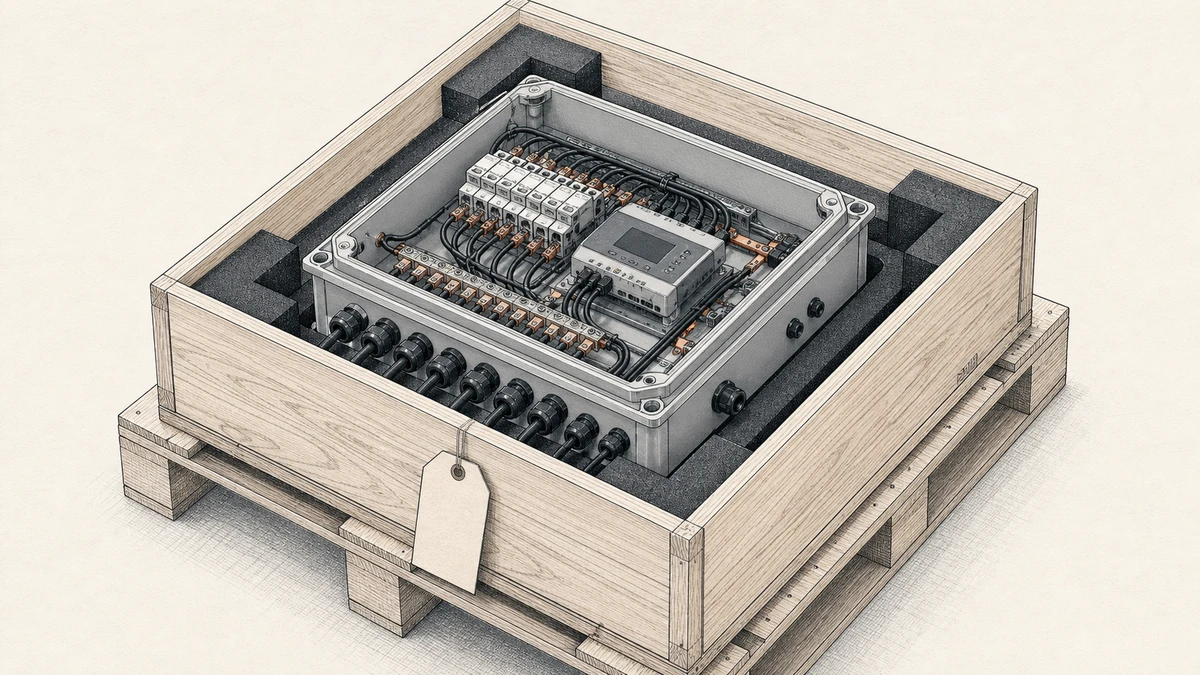
Use the following checklist as a project-level guide and adapt it to the approved design, local regulations, and site method statement.
| Check Item | Confirmed |
|—|—|
| Combiner box model matches project specification | |
| Enclosure is clean, sealed, and undamaged | |
| String labels match drawings | |
| Positive and negative polarity verified | |
| Open-circuit voltage recorded for each string | |
| Insulation resistance test completed | |
| Fuse ratings match design | |
| SPD installed and status contact checked | |
| DC breaker or switch operation verified | |
| Grounding and bonding checked | |
| Terminal torque verified | |
| Monitoring device powered correctly | |
| Communication address configured | |
| Current and voltage scaling verified | |
| Channel mapping checked against physical strings | |
| Alarm thresholds and delays configured | |
| Alarm display verified in monitoring platform | |
| Commissioning records completed | |
PV combiner box string monitoring is the measurement and supervision of individual PV string performance inside a combiner box. It typically monitors string current, voltage, and protection device status so operators can detect DC-side faults more quickly.
String-level alarms help identify faults that may not immediately stop the inverter but still reduce energy production. Examples include blown fuses, damaged connectors, degraded modules, open strings, and abnormal current imbalance.
Alarm points should be based on the PV string design, equipment ratings, site conditions, and commissioning measurements. After the system operates under stable irradiance, the alarm thresholds and delays should be reviewed against real baseline data to reduce nuisance alarms and improve fault detection.