住所
304ノース・カーディナル
セント・ドーチェスター・センター(マサチューセッツ州02124
勤務時間
月曜日~金曜日:午前7時~午後7時
週末午前10時~午後5時
住所
304ノース・カーディナル
セント・ドーチェスター・センター(マサチューセッツ州02124
勤務時間
月曜日~金曜日:午前7時~午後7時
週末午前10時~午後5時

Understanding DC SPD Type 2 specifications enables proper surge protection device selection for photovoltaic system applications. This comprehensive specification guide examines IEC 61643-31 classification standards, test waveform characteristics, voltage protection level requirements, and Type 1 vs Type 2 vs Type 3 distinctions. Engineers and specifiers will find detailed rating criteria, application guidelines, and selection matrices for matching SPD capabilities to installation requirements.
Type 2 surge protective devices represent the most commonly specified protection class for inverter inputs, combiner box outputs, and equipment-level protection in solar installations. These devices test with 8/20μs current waveforms simulating induced surge characteristics from indirect lightning strikes and switching transients. Understanding Type 2 specifications and appropriate application boundaries ensures effective protection without over-specification increasing costs unnecessarily.
IEC 61643-31 establishes three-tier classification system for photovoltaic surge protective devices based on tested energy handling capabilities and intended installation locations. This standardized classification replaced earlier regional systems (European EN, American UL, Chinese GB) creating internationally recognized SPD categories. The classification enables consistent specification language across global PV projects eliminating confusion from competing national standards.
Type 1 classification designates highest energy-handling SPDs tested with 10/350μs current waveforms representing direct lightning current pulses. These devices must withstand impulse current (Iimp) ranging 12.5kA to 100kA per conductor demonstrating capability to survive partial lightning strike energy. Type 1 devices install at service entrances, array origins, and locations potentially exposed to direct strike energy requiring maximum protection capability.
Type 2 classification identifies intermediate protection level suitable for equipment locations and secondary protection stages. Type 2 devices test with 8/20μs nominal discharge current (In) waveforms simulating induced surge currents from electromagnetic coupling or attenuated direct strikes. Typical In ratings range 5kA to 40kA per conductor—substantially lower than Type 1 but adequate for surges having passed through upstream protective elements or originating from indirect coupling mechanisms.
Type 3 classification covers lowest-energy SPDs tested with combination wave generators producing simultaneous voltage and current transients. These devices primarily protect individual equipment items in already-protected environments. Type 3 SPDs rarely appear in PV main DC circuits but sometimes protect specialized instrumentation or monitoring equipment requiring supplemental fine protection beyond system-level Type 1 and Type 2 devices.
| 分類 | テスト波形 | Typical Current Rating | Primary Application | Installation Location |
|---|---|---|---|---|
| タイプ1 | 10/350μs | 25-100kA (Iimp) | Direct strike protection | Array origin, service entrance |
| タイプ2 | 8/20μs | 10-40kA (In) | Induced surge protection | Inverter input, combiner output |
| タイプ3 | コンビネーション・ウェーブ | 1-10kA | Equipment-level fine protection | Individual equipment, instrumentation |
The 8/20μs designation for Type 2 SPDs describes impulse current waveform shape: 8μs rise time from zero to peak current, 20μs decay time from peak to 50% of peak value. This waveform simulates electromagnetic induction from nearby lightning strikes (100-500 meters distance) or attenuated direct strike energy having passed through conductor impedance and upstream protection. The relatively fast rise time (8μs) represents significant di/dt creating substantial voltage stress on SPD components.
Compare Type 2 waveform to Type 1’s 10/350μs: much slower rise (10μs vs 8μs) but dramatically longer duration (350μs vs 20μs). The extended duration of 10/350μs waveform delivers approximately 10× more energy than 8/20μs at equal peak current. This energy difference explains why Type 1 devices require more robust construction and cost significantly more than Type 2 despite similar voltage ratings.
Testing laboratories inject specified test current through SPD under test measuring resulting voltage protection level (clamping voltage) appearing across SPD terminals. Type 2 tests typically use nominal discharge current (In) plus maximum discharge current (Imax) equal to twice nominal value. A 20kA Type 2 SPD must survive 20kA nominal test plus 40kA maximum test proving adequate margin for real-world surge variability.
重要な洞察: The test classification (Type 1, 2, or 3) indicates SPD’s tested capability—not necessarily its application location. Type 2 SPDs can install anywhere in PV system including array origins if threat assessment determines 8/20μs surge characteristics are maximum expected. Conversely, some specifications mandate Type 1 at all locations despite potential over-specification for downstream positions.
Maximum continuous operating voltage (MCOV or Uc) defines highest steady-state voltage SPD withstands indefinitely without degradation. MCOV must exceed maximum system DC operating voltage under all conditions including temperature extremes affecting photovoltaic module voltage output. Photovoltaic open-circuit voltage increases significantly at low temperatures—systems with 600V nominal may reach 750V at −25°C requiring Type 2 SPD with 850V+ MCOV rating.
IEC 61643-31 requires MCOV to exceed system maximum voltage by minimum safety margin preventing continuous voltage stress degrading varistor elements. Metal oxide varistors (MOVs) forming the core of most Type 2 SPDs conduct small leakage current even at voltages below nominal activation threshold. This leakage increases exponentially as voltage approaches activation level generating internal heat that accelerates aging and reduces service life.
Common Type 2 DC SPD MCOV ratings for solar applications:
- 600V systems: Specify 850V to 1000V MCOV
- 1000V systems: Specify 1200V to 1500V MCOV
- 1500V systems: Specify 1800V to 2000V MCOV
Calculate required MCOV using: MCOV ≥ 1.25 × Voc(min temp) where Voc(min temp) represents string open-circuit voltage at lowest expected ambient temperature. The 1.25 factor provides margin for voltage transients, measurement uncertainties, and component tolerances ensuring MCOV never reaches 100% of rating during normal operation.
Voltage protection level (VPL or Up) specifies maximum voltage appearing at protected equipment terminals when SPD diverts rated surge current. VPL represents the critical specification determining protection effectiveness—lower VPL provides better equipment protection but requires tighter manufacturing tolerances increasing cost. Equipment insulation ratings must exceed SPD VPL with margin ensuring surge events cannot damage protected loads.
Type 2 SPD voltage protection levels typically range 1500V to 3000V for DC photovoltaic applications depending on MCOV rating and protection element design. Higher MCOV ratings generally produce higher VPL—an inherent tradeoff in varistor-based protection where devices conducting at lower voltages (better protection) also begin conducting at voltages closer to normal operating voltage (reduced margin).
VPL specification represents measured value—not calculated or theoretical. Manufacturers test VPL by injecting rated discharge current (typically In and Imax) through SPD while measuring resulting voltage with calibrated oscilloscope. Published VPL must not exceed measured value ensuring conservative ratings. Some manufacturers publish VPL at multiple current levels (VPL at In, VPL at Imax) showing protection performance across surge current range.
Selecting appropriate VPL requires knowing protected equipment insulation level or impulse withstand voltage. Inverter DC input terminals typically withstand 6kV impulse per IEC 62109-2 requirements. Type 2 SPD with 2500V VPL provides adequate protection margin (6000V − 2500V = 3500V safety margin) accounting for voltage drops in wiring and uncertainty factors. Lower VPL improves protection but verify SPD MCOV still provides adequate margin above maximum system voltage.
| システム電圧 | Typical MCOV | Typical VPL | Equipment Insulation | Protection Margin |
|---|---|---|---|---|
| 600V nominal | 850-1000V | 1800-2200V | 6000V (IEC) | 3800-4200V ✅ |
| 1000V nominal | 1200-1500V | 2500-3000V | 8000V (IEC) | 5000-5500V ✅ |
| 1500V nominal | 1800-2000V | 3500-4000V | 10000V (IEC) | 6000-6500V ✅ |
Nominal discharge current (In) defines the surge current value used for Type 2 classification testing and performance verification. Manufacturers must demonstrate SPD survives minimum 15 surge applications at In rating without failure or performance degradation exceeding specified limits. This multiple-surge testing proves SPD longevity under realistic conditions where installations experience numerous surge events over service life.
Common Type 2 In ratings for PV applications: 5kA, 10kA, 15kA, 20kA, 30kA, and 40kA per pole. Higher In ratings provide greater energy-handling capability and longer service life but increase device size and cost. Selection depends on lightning exposure assessment and desired service life considering surge frequency. High-exposure locations experiencing frequent thunderstorm activity benefit from higher In ratings reducing replacement frequency.
The relationship between In and maximum discharge current (Imax) follows standard ratio: Imax = 2 × In. This relationship means 20kA Type 2 SPD must survive testing at 40kA maximum current demonstrating adequate margin for surge current variability. Some manufacturers test beyond minimum 2× requirement providing additional safety margin documented in test reports.
⚠️ 重要: In rating alone doesn’t determine total energy capacity—waveform duration critically affects total energy absorption. Type 1 device with lower Iimp than Type 2 device’s In rating may still handle more total energy due to 10/350μs waveform’s longer duration. Compare energy ratings (measured in kJ) when selecting between Type 1 and Type 2 classes for specific applications.
The fundamental distinction between Type 1 and Type 2 classifications stems from vastly different energy handling capabilities proven through standardized testing. Type 1 devices test with 10/350μs waveform carrying approximately 10× more energy per ampere than Type 2’s 8/20μs waveform. A 25kA Type 1 SPD handles roughly 250kJ total energy while 40kA Type 2 handles only 80kJ—despite higher peak current rating, Type 2 absorbs less total energy.
Calculate specific energy (energy per ohm of impedance) using standard formula: W/R = 0.5 × I² × t where I is peak current and t is effective duration. For 10/350μs waveform at 25kA: W/R ≈ 250 kJ/Ω. For 8/20μs waveform at 40kA: W/R ≈ 80 kJ/Ω. This threefold energy difference explains why Type 1 devices employ larger varistor discs, more robust terminal connections, and heavier-duty enclosures than Type 2 counterparts.
The practical implication: Type 2 SPDs adequate for locations where surge energy has been attenuated by conductor impedance, upstream SPD coordination, or protection from direct lightning exposure. Type 1 SPDs mandatory for exposed locations potentially experiencing unattenuated direct strike energy. Many installations use Type 1 at array origin (maximum exposure) coordinated with Type 2 at inverter input (protected location) balancing protection effectiveness with cost optimization.
Type 2 SPDs typically cost 40-60% of equivalent-voltage Type 1 devices reflecting reduced component requirements and simpler construction. Standard Type 2 SPD for 1000V PV system costs $150-300 depending on In rating and manufacturer. Comparable Type 1 device costs $400-700. For large installations requiring multiple SPDs, this cost difference significantly affects project budgets justifying careful analysis of whether Type 1 capability is genuinely required at each location.
Physical size differences also matter in space-constrained combiner boxes and inverter enclosures. Type 2 SPDs occupy approximately 40-60mm width on standard DIN rail depending on rating and number of poles. Type 1 devices require 60-100mm width for equivalent voltage ratings. In 8-string combiner installing string-level SPDs, using Type 2 instead of Type 1 saves 160-320mm DIN rail space potentially allowing use of smaller, less expensive enclosure.
Weight considerations affect mounting in rooftop combiner boxes where load-bearing capacity may be limited. Type 2 SPDs weigh 200-400g each vs. 500-1000g for Type 1 units. Eight-string installation: Type 2 total weight 1.6-3.2kg vs. Type 1 weight 4-8kg. The 2-5kg difference matters when mounting multiple combiner boxes on aging roof structures where additional dead load requires structural engineering review.
Use Type 1 SPDs when:
– Installing at array origin where direct lightning strikes might inject unattenuated energy
– System located in high-exposure areas (mountaintops, coastal areas, open plains without nearby structures)
– Local lightning ground flash density exceeds 5 flashes/km²/year indicating extreme exposure
– Authority having jurisdiction (AHJ) mandates Type 1 for specific locations per local amendments
– Equipment protected has exceptionally high replacement cost (>$100k) justifying maximum protection investment
Use Type 2 SPDs when:
– Installing at inverter DC input where conductor impedance provides attenuation
– Location is second-stage protection with upstream Type 1 SPD coordination
– System in moderate-exposure area (suburban, urban with nearby taller structures providing shielding)
– Local lightning density 1-5 flashes/km²/year representing moderate activity
– Cost optimization is priority and threat assessment supports reduced capability
Use Type 1+Type 2 coordinated approach when:
– Large commercial or utility-scale installation justifying comprehensive protection investment
– High equipment value (>$50k inverters) where damage costs exceed additional SPD expense
– Critical applications where downtime is unacceptable requiring maximum protection reliability
– Threat assessment indicates both direct strike risk (requiring Type 1) and induced surge risk (Type 2 handles)
Metal oxide varistors form the primary protection element in majority of Type 2 DC SPDs due to favorable cost-performance balance. MOVs use sintered zinc oxide ceramic exhibiting voltage-dependent resistance: extremely high resistance (>1GΩ) at normal operating voltage transitioning to low resistance (1-10Ω) during surge events. This nonlinear I-V characteristic provides automatic surge diversion without requiring external triggering or control circuits.
MOV voltage rating selection determines clamping voltage and MCOV capabilities. Manufacturers specify MOVs by varistor voltage (V₁mA)—the voltage producing 1mA current through device during standardized testing. Select MOVs with V₁mA approximately 1.5-1.8× desired MCOV ensuring adequate margin above continuous operating voltage. For 1000V MCOV application, specify MOVs with V₁mA 1500-1800V providing proper operating margin.
MOV degradation represents primary limitation affecting service life. Each surge event consumes small amount of varistor material through localized heating and grain boundary modification. Cumulative energy absorption gradually reduces varistor voltage (device conducts at progressively lower voltages) eventually reaching point where device begins conducting during normal operation. This degradation manifests as increased leakage current and reduced surge capacity requiring SPD replacement before complete failure.
Silicon avalanche diodes provide alternative protection technology offering faster response time and tighter voltage clamping than MOVs. SADs transition from blocking to conducting in <1 nanosecond (vs. 25-50ns for MOVs) providing superior protection against fast-rising surge transients. The tighter clamping voltage—typically 10-15% lower than equivalent MOV—better protects sensitive power electronics in modern inverters.
The primary disadvantage of SAD technology: lower energy handling capability per device volume. Individual SAD chips handle 400W to several kW pulse power requiring parallel arrays for high-current Type 2 applications. MOVs achieve same performance in smaller package with single varistor disc. SADs also exhibit higher cost per joule protected making them economically viable primarily for lower-current applications or specialized high-performance requirements.
Hybrid SPD designs combine MOV and SAD technologies exploiting complementary characteristics. Fast-acting SAD provides initial surge response with tight voltage clamping while high-energy MOV handles bulk surge current once SAD reaches conduction threshold. This hybrid approach delivers fast response, tight clamping, and adequate energy capacity in single package costing 20-40% more than MOV-only designs but providing superior protection performance.
Gas discharge tubes offer highest single-device current handling capability (100kA+) but slower response time (100-300ns) and higher voltage overshoot during activation. GDTs rarely appear as sole protection element in Type 2 SPDs but frequently integrate in multi-stage hybrid designs. The GDT handles initial high-current surge phase while MOV provides fast fine clamping for surge tail and lower-amplitude transients.
GDT-MOV hybrid SPDs typically show three-stage response:
1. Surge arrival triggers MOV conduction providing initial voltage limiting
2. Rising surge current voltage causes GDT ionization and arc formation
3. GDT arc diverts majority of surge current while MOV limits residual voltage
This coordination provides combined benefits: GDT’s high current capacity extends SPD service life by preventing MOV from absorbing full surge energy. MOV’s fast response prevents voltage overshoot during GDT ionization delay. The result: longer-lasting protection with tighter voltage control than either technology alone.
| Protection Technology | 応答時間 | Energy Capacity | Clamping Voltage | 代表的なアプリケーション |
|---|---|---|---|---|
| MOV Only | 25-50ns | 高い | Good (1.8-2.5× MCOV) | Standard Type 2, cost-optimized |
| SAD Only | <1ns | Limited | Excellent (1.5-1.8× MCOV) | Low-current, fast response critical |
| MOV + SAD Hybrid | <1ns | 高い | Excellent (1.5-2.0× MCOV) | Premium Type 2, sensitive loads |
| GDT + MOV Hybrid | 25-50ns | 非常に高い | Good (2.0-3.0× MCOV) | High-energy Type 2, long service life |
🎯 プロのアドバイス: Request manufacturer test reports documenting actual surge testing results rather than relying solely on datasheet specifications. Test reports reveal real-world performance including VPL variation across current range, follow current interruption capability, and aging test results showing performance after multiple surge applications. These details indicate quality differences not apparent from basic specifications.

IEC 61643-31 specifies comprehensive test sequences Type 2 SPDs must pass for classification certification. The testing protocol includes operating duty tests, thermal stability verification, short-circuit interruption capability, and follow current limitation. Manufacturers submit samples to accredited testing laboratories (TÜV, UL, Intertek, etc.) demonstrating compliance with all requirements before claiming Type 2 classification.
Operating duty test forms the primary verification requiring SPD to survive 15 surge applications at nominal discharge current (In) plus 1 surge at maximum discharge current (Imax = 2×In). These tests apply 8/20μs current waveform with specified rise time and duration tolerances. After testing, SPD must show VPL within specified limits and exhibit no visible damage, tracking, or excessive leakage current increase.
Thermal stability testing verifies SPD operation at maximum continuous operating voltage (MCOV) under elevated temperature (85°C typical) for extended periods (1000 hours minimum). This accelerated aging test confirms varistor stability and validates that thermal effects from normal voltage stress won’t cause premature failure. Devices showing excessive leakage current increase (>100% of initial) or thermal runaway fail certification.
United States installations often specify UL 1449 certification in addition to IEC standards ensuring product meets North American safety requirements. UL 1449 Fourth Edition establishes Voltage Protection Rating (VPR) categories: 600V, 700V, 800V, 1000V, 1200V, 1500V, 1800V, 2000V, 2500V, 3000V, 4000V, 5000V, and 6000V. These VPR values represent measured voltage protection levels but use different test methodology than IEC VPL creating potential confusion when comparing specifications.
UL 1449 requires abnormal overvoltage test verifying SPD behavior when subjected to continuous overvoltage (115% of MCOV) simulating system fault conditions. SPDs must either survive test without failure or fail in safe mode without creating fire hazard, opening enclosure, or projecting parts. This test addresses safety concerns about SPD failures in occupied buildings ensuring devices don’t create additional hazards beyond surge damage they protect against.
UL certification also mandates short-circuit current rating (SCCR) verification testing SPD ability to safely fail when subjected to available fault current. PV systems can deliver substantial fault current from parallel string arrays potentially exceeding 1000A. UL-listed SPDs specify minimum SCCR (typically 5kA or 10kA for PV applications) and must demonstrate safe failure mode when subjected to fault currents up to specified rating.
Third-party certification from recognized testing laboratories provides objective verification of SPD performance claims. Uncertified products claiming Type 2 classification lack independent proof of capabilities potentially delivering inadequate protection despite manufacturer specifications. Insurance companies and authorities having jurisdiction increasingly require certified SPDs rejecting uncertified alternatives regardless of claimed specifications.
Look for certification marks on SPD nameplates or documentation:
- IEC 61643: TÜV, VDE, CSA, Intertek certification marks
- UL 1449: UL mark with file number allowing verification on UL online database
- Regional standards: CE mark (Europe), CCC mark (China), PSE mark (Japan)
Request manufacturer certificate of conformity and test reports documenting actual measured performance. These documents reveal whether SPD barely meets minimum standards or significantly exceeds requirements providing performance margin. Some manufacturers publish test reports showing performance at currents beyond In rating (e.g., test results at 1.5× In, 2× In) demonstrating robust design margins.
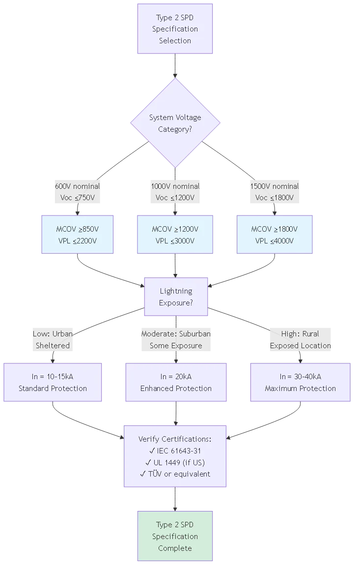
Primary selection criterion for Type 2 SPDs matches device voltage rating to system DC voltage class. Calculate required MCOV from string configuration accounting for series-connected module count, individual module Voc, and temperature coefficient effects. Add safety margin (typically 25%) above calculated maximum voltage ensuring SPD never operates near voltage rating limits.
600V Class Systems (residential, small commercial):
– String configuration: 12-18 modules @ 40-50V each
– Maximum Voc: 600-750V at −25°C
– Required MCOV: ≥850V
– Recommended Type 2: 1000V MCOV, 15-20kA In, VPL ≤2200V
1000V Class Systems (commercial, industrial):
– String configuration: 20-28 modules @ 40-50V each
– Maximum Voc: 1000-1200V at −25°C
– Required MCOV: ≥1200V
– Recommended Type 2: 1500V MCOV, 20-30kA In, VPL ≤3000V
1500V Class Systems (utility-scale):
– String configuration: 28-36 modules @ 45-55V each
– Maximum Voc: 1500-1800V at −25°C
– Required MCOV: ≥1800V
– Recommended Type 2: 2000V MCOV, 30-40kA In, VPL ≤4000V
Nominal discharge current (In) selection depends on expected lightning exposure quantified through isokeraunic level (thunderstorm days per year) or ground flash density (strikes per km² per year). Higher lightning activity justifies higher In ratings extending SPD service life and reducing replacement frequency.
Low Exposure (0-20 thunderstorm days/year, <2 flashes/km²/year): – Urban areas, locations with nearby tall structures providing shielding – Type 2 specification: In = 10-15kA – Expected service life: 8-12 years between replacements – Cost optimization: acceptable to use minimum ratings Moderate Exposure (20-40 thunderstorm days/year, 2-5 flashes/km²/year):
– Suburban areas, moderate elevation, some shielding available
– Type 2 specification: In = 20kA
– Expected service life: 5-8 years between replacements
– Balance: moderate enhancement vs. cost increase
High Exposure (40+ thunderstorm days/year, >5 flashes/km²/year):
– Rural areas, mountaintops, coastal locations, minimal shielding
– Type 2 specification: In = 30-40kA
– Expected service life: 3-5 years even with high rating
– Consider: Type 1 at array origin for better protection
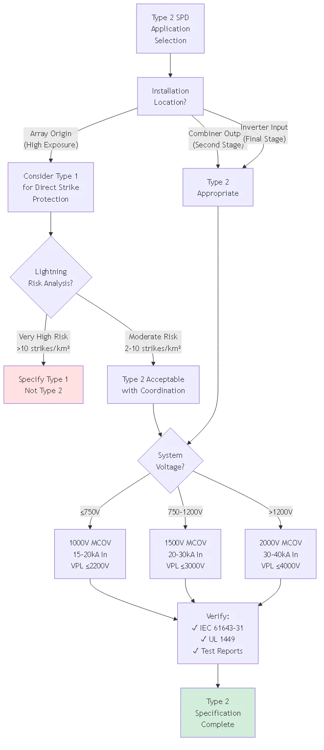
When specifying Type 2 SPDs in coordinated multi-stage protection system, ensure proper rating relationships between stages. Upstream devices (typically Type 1 at array origin) should specify higher current ratings than downstream Type 2 devices at inverter inputs. This creates natural energy distribution where robust upstream device handles bulk surge energy while downstream device provides fine protection for residual transients.
Typical coordinated specification:
- Upstream (array origin): Type 1, 50kA Iimp, 2000V VPL
- Minimum separation: 10m conductor or 15μH inductor
- Downstream (inverter input): Type 2, 20kA In, 1800V VPL
Verify voltage protection level relationship allows proper coordination. While downstream SPD specifies lower VPL (1800V vs 2000V), conductor impedance between stages prevents simultaneous conduction. During surge event, upstream device sees and responds to surge first, limiting voltage that appears at downstream location to level below downstream SPD activation threshold except for extreme events exceeding upstream capacity.
| Application Scenario | Recommended Type 2 Rating | Installation Location | Typical Cost Range |
|---|---|---|---|
| Residential 5kW, Low Exposure | 1000V MCOV, 15kA In | Inverter DC input only | $150-250 |
| Commercial 50kW, Moderate | 1500V MCOV, 20kA In | Combiner + Inverter (2-stage) | $400-600 total |
| Utility 1MW, High Exposure | 2000V MCOV, 40kA In | Multiple Type 2 at inverters | $3000-5000 per inverter |
| Rooftop Critical Load | 1000V MCOV, 20kA In, Premium MOV+SAD | String + Combiner + Inverter (3-stage) | $800-1200 total |
The fundamental difference lies in energy handling capacity proven through different test waveforms. Type 1 SPDs test with 10/350μs impulse current simulating direct lightning strikes requiring devices to handle 10× more energy per ampere than Type 2 devices. Type 2 SPDs test with 8/20μs waveform representing induced surges from nearby lightning or attenuated direct strikes requiring substantially less energy capacity.
Type 1 devices typically cost 2-3× more than Type 2 equivalents and occupy 50-70% more enclosure space. This cost-size difference makes Type 2 preferable when threat assessment confirms direct lightning exposure is unlikely or upstream protection provides adequate energy attenuation. Most PV installations use Type 1 at exposed array origins coordinated with Type 2 at protected inverter locations creating defense-in-depth at optimized cost.
The classification doesn’t dictate installation location—properly selected Type 2 SPDs can install anywhere including array origins if lightning risk assessment supports this decision. However, conservative design practice specifies Type 1 for maximum-exposure locations and reserves Type 2 for secondary protection stages where surge characteristics match Type 2 tested capabilities.
Type 2 SPDs can install at array origins when lightning risk assessment confirms low probability of direct strikes and local exposure characteristics produce primarily induced surge threats. Urban rooftop installations surrounded by taller buildings rarely experience direct strikes making Type 2 adequate for array-origin protection. Similarly, arrays with properly designed external lightning protection system (air terminals, down conductors) preventing direct attachment to array conductors may specify Type 2 instead of Type 1.
However, most electrical engineers specify Type 1 at array origins following conservative design practice and recognizing relatively modest cost differential ($200-400 per location) compared to potential inverter replacement costs ($5,000-50,000 depending on size). The enhanced protection provides peace of mind and may satisfy insurance requirements expecting “maximum available protection” at exposed locations.
Document decision rationale if specifying Type 2 at array origin rather than Type 1. Perform lightning risk assessment per IEC 62305-2 calculating expected annual frequency of dangerous events. When calculated risk remains below acceptable threshold (typically <10% probability over 25-year system life), Type 2 specification is technically justified. Retain assessment documentation proving due diligence for insurance claims or failure investigations.
For 600V nominal photovoltaic systems, specify Type 2 SPD with minimum 850V MCOV accounting for temperature-compensated open-circuit voltage extremes. Calculate actual required MCOV from: string Voc at minimum temperature × temperature coefficient × 1.25 safety factor. For typical 600V system using modules with −0.28%/°C coefficient: 600V × 1.20 (at −25°C) × 1.25 = 900V MCOV minimum.
Standard Type 2 SPDs for 600V systems specify 1000V MCOV providing comfortable margin above calculated 900V minimum. This margin accounts for voltage measurement uncertainties, module manufacturing tolerances, and potential overvoltage from partial shading or module mismatch. Avoid specifying MCOV ratings exactly matching calculated requirements—inadequate margin leads to premature SPD degradation from chronic voltage stress.
Higher MCOV ratings generally produce higher voltage protection levels (VPL) since varistor elements conducting at higher voltages also clamp at proportionally higher levels. For 600V systems, typical VPL ranges 1800-2200V for SPDs with 1000V MCOV. This VPL provides adequate protection for standard inverter insulation ratings (6kV impulse withstand per IEC 62109) with substantial safety margin.
Most modern Type 2 SPDs include visual status indicators (LED lights or mechanical flags) displaying device condition. Green indicator signals healthy operation while red, yellow, or dark indicator shows failure or degradation requiring immediate replacement. Check status indicators quarterly during routine maintenance documenting device condition in maintenance logs.
Some failures occur suddenly after major surge events immediately triggering status indicators. Other failures develop gradually through cumulative surge exposure or aging manifesting as slowly increasing leakage current and VPL drift. Annual electrical testing using portable surge generators can detect degradation before status indicators show failure allowing proactive replacement rather than reactive emergency response.
Additional failure indicators include: physical enclosure damage (cracks, burn marks, discoloration), unusual odors suggesting overheating, increased operating temperature detected during thermal imaging inspection, or nuisance activation indicated by repeatedly cycling status indicators. Any of these signs warrant immediate SPD replacement even if status indicator hasn’t flagged failure. Failed SPDs provide no surge protection leaving equipment vulnerable to damage.
Type 2 SPD service life depends on cumulative surge exposure rather than calendar time. Installations in low-lightning-activity areas (urban, low isokeraunic level) may operate 10-15 years before requiring replacement. High-exposure locations (rural, mountaintop, high thunderstorm frequency) might require replacement every 3-5 years despite identical SPD specifications.
Manufacturers specify total energy absorption capacity (measured in kJ) representing cumulative surge energy SPD can handle before requiring replacement. A 20kA Type 2 SPD might specify 100kJ total capacity. Each surge event consumes portion of this capacity—10kA surge at 8/20μs waveform consumes approximately 25kJ leaving 75kJ remaining capacity. After four similar events, SPD reaches end of useful life requiring replacement.
Proactive replacement based on manufacturer recommended service life (typically 10 years) provides conservative approach avoiding unexpected failures. Some installations implement condition-based replacement testing SPDs annually and replacing devices showing VPL degradation >10% from initial rating or leakage current increase >100%. This condition-based approach optimizes replacement timing avoiding premature disposal of functional devices while preventing failure-induced downtime.
Mixing Type 1 and Type 2 SPDs in coordinated multi-stage protection represents standard industry practice optimizing protection effectiveness versus cost. Typical configuration installs Type 1 SPDs at array origins (maximum exposure) coordinated with Type 2 SPDs at inverter inputs (protected location) creating defense-in-depth protection. The Type 1 handles direct strike energy while Type 2 provides final protection stage for residual transients.
Proper coordination requires minimum 10-meter conductor separation between SPD stages or equivalent decoupling inductance ensuring upstream device activates before downstream device. This separation allows natural energy distribution where higher-rated upstream SPD diverts bulk surge current while lower-rated downstream SPD handles residual voltage after conductor impedance drop. Both devices contribute to total protection without competing for surge current control.
Verify voltage protection level (VPL) relationship supports proper coordination hierarchy. While counterintuitive, downstream SPD typically specifies lower VPL than upstream device because conductor impedance ensures upstream activation occurs first. During surge event: upstream SPD clamps to its VPL (e.g., 2000V), conductor impedance drops additional voltage, downstream SPD sees reduced voltage below its activation threshold. This coordinated operation delivers optimal protection combining high energy capacity with tight voltage clamping.
Minimum certification requirements for professional PV installations include IEC 61643-31 compliance verified by accredited testing laboratory (TÜV, VDE, CSA, Intertek, etc.) and UL 1449 Fourth Edition listing for United States projects. These certifications prove SPD meets standardized testing requirements for Type 2 classification and satisfies safety standards preventing devices from creating additional hazards when failing.
Additional valuable certifications include: ISO 9001 quality management system certification proving manufacturer maintains consistent production processes, environmental certifications (RoHS, REACH) verifying restricted substance compliance, and regional marks (CE for Europe, CCC for China) when required by installation location. Some specifications also mandate specific testing beyond minimum certification such as salt spray resistance for coastal installations or extended temperature testing for extreme climate locations.
Request manufacturer certificate of conformity and actual test reports documenting measured performance rather than relying solely on certification marks. Test reports reveal whether SPD barely meets minimum standards or significantly exceeds requirements providing performance margin. Look for test results showing: VPL at multiple current levels (In, 1.5×In, 2×In), follow current interruption capability, aging test results after 15 surge applications, and thermal stability data proving long-term reliability.
Type 2 DC surge protective device specifications provide critical selection criteria ensuring effective photovoltaic system protection at optimized cost. Understanding IEC 61643-31 classification standards, test waveform characteristics, voltage protection level requirements, and nominal discharge current ratings enables engineers to specify appropriate SPD capabilities matching installation threat levels without unnecessary over-specification.
重要なポイント
1. Type 2 classification tests SPDs with 8/20μs waveform representing induced surge characteristics requiring less energy capacity than Type 1’s 10/350μs direct strike simulation
2. MCOV rating must exceed maximum system voltage by 25% minimum margin preventing continuous voltage stress from degrading varistor elements
3. Voltage protection level (VPL) determines actual protection effectiveness—lower VPL provides better equipment protection but requires tighter manufacturing tolerances
4. Nominal discharge current (In) selection depends on lightning exposure assessment with higher ratings extending service life in high-activity locations
5. Type 1 and Type 2 SPDs coordinate effectively in multi-stage protection systems with upstream Type 1 handling direct strikes and downstream Type 2 providing equipment-level fine protection
Proper Type 2 SPD specification requires balancing protection requirements, cost constraints, and installation-specific threat assessment. Conservative specifications using higher ratings provide enhanced protection and longer service life but increase initial investment. Optimized specifications match SPD capabilities to actual expected threats eliminating unnecessary cost while maintaining adequate protection for 25-year system operational lifetime.
Related Resources:
- DC SPD for Solar Systems: Type 1 vs Type 2 Applications
- How to Wire DC SPD: Installation Diagrams and Grounding Methods
- DC Circuit Breaker Specifications for PV Protection
Ready to specify compliant Type 2 DC SPDs for your solar projects? Contact our protection engineering team for application-specific SPD selection assistance, coordination analysis, and certification verification ensuring your surge protection specifications meet both performance requirements and applicable standards.
最終更新日 December 2025
著者 SYNODEテクニカルチーム
レビュー Surge Protection Engineering Department