주소
304 북쪽 추기경
세인트 도체스터 센터, MA 02124
근무 시간
월요일~금요일: 오전 7시~오후 7시
주말: 주말: 오전 10시 - 오후 5시
주소
304 북쪽 추기경
세인트 도체스터 센터, MA 02124
근무 시간
월요일~금요일: 오전 7시~오후 7시
주말: 주말: 오전 10시 - 오후 5시

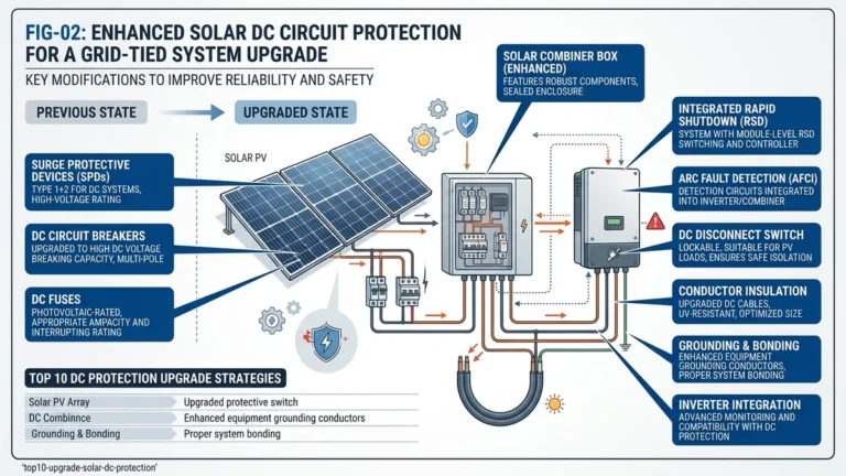
At utility scale, moving from 1000V to 1500V architecture changes more than equipment labels—it changes how the disconnect has to survive and extinguish DC energy during switching.
A 1500V DC isolator switch is a load-break or no-load disconnect device that physically separates a PV string or array from downstream equipment, creating a visible isolation point for maintenance and fault response. At 1500V DC, the engineering challenge is not a simple scale-up from 1000V hardware.
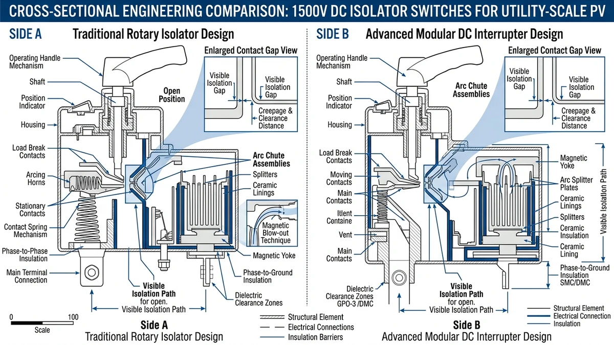
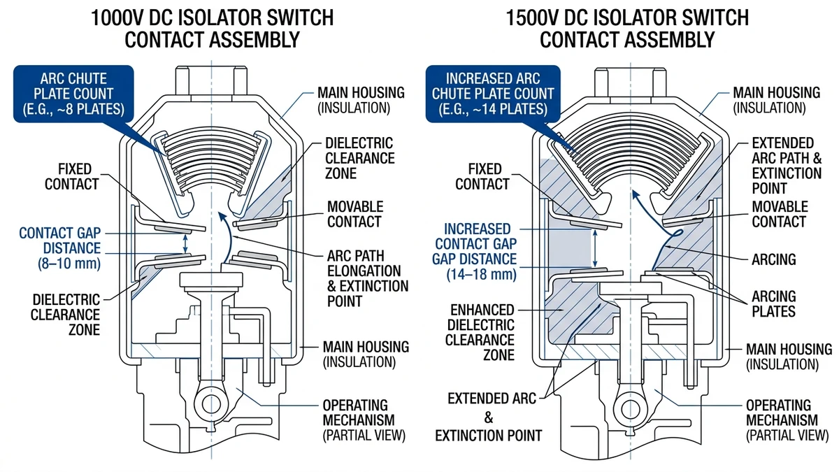
DC arcs do not self-extinguish. Unlike AC systems, where current crosses zero repeatedly, DC current is continuous. At 1500V, the arc energy available during contact separation is roughly 2.25× greater than at 1000V because energy scales with V². That means contact gap geometry, arc chute design, and dielectric clearances must be redesigned rather than lightly derated from lower-voltage devices.
IEC 60947-3 requires 1500V DC isolators to demonstrate full breaking capacity at rated voltage with arc extinction contained inside the enclosure. In practice, contact gap distances often increase from about 8–10 mm at 1000V to 14–18 mm at 1500V to achieve dependable interruption under worst-case conditions.
In a 120 MW ground-mount installation in Inner Mongolia in 2023, the shift from 1000V to 1500V string architecture reduced the number of combiner boxes by roughly 35%, but every string-level DC 스위치 단로기 had to be re-specified for the higher voltage class. Teams that substituted 1000V-rated isolators saw contact welding during commissioning.
For broader coordination context, the DC isolator switch selection guide explains how voltage class matching fits into the overall DC protection chain.
Once the voltage class is set, the next design choice is placement, because isolator location determines how precisely the plant can be shut down, serviced, and fault-segmented.
Where you place a 1500V DC isolator switch directly affects fault isolation speed, maintenance flexibility, and protection granularity. The two common strategies—string-level and array-level placement—serve different operational goals.
String-level isolators are installed at the output of each PV string, usually inside or immediately upstream of the combiner box. In a 1500V architecture, each string commonly operates with an open-circuit voltage in the 1000–1500 V range and a short-circuit current of 10–18 A. A disconnect at this point lets technicians de-energize one string without taking adjacent strings offline.
In a 60 MW ground-mount installation in Inner Mongolia in 2023, string-level isolation allowed technicians to identify and isolate underperforming strings in under 90 seconds per event, cutting maintenance-related energy loss by an estimated 30% versus array-level-only switching.
IEC 62548-1 supports string-level disconnection where individual fault isolation and reverse current protection are needed, especially when string current conditions could exceed module reverse-current capability.
Array-level isolators sit at the combiner output or inverter DC input and isolate an entire sub-array, typically 16–24 strings at a time. This reduces component count and simplifies procurement, but one fault can remove a much larger section of generation from service.
For inverter maintenance or commissioning, array-level disconnectors rated at 1500 VDC and roughly 630–1000 A are common, and they must satisfy IEC 60947-3 for DC switching duty.
| 매개변수 | String-Level Isolator | Array-Level Isolator |
|---|---|---|
| Typical voltage rating | 1000-1500 VDC | 1000-1500 VDC |
| Typical current rating | 15–32 A | 400–1000 A |
| Isolation granularity | Per string | Per sub-array (16–24 strings) |
| Fault isolation speed | Under 2 min per string | Entire array offline |
| Component count (50 MW plant) | High (hundreds of units) | Low (tens of units) |
| Governing standard | IEC 62548-1, IEC 60947-3 | IEC 60947-3 |
| Typical enclosure location | Inside combiner box | Combiner output / inverter DC input |
For deeper context on placement and protection coordination, the DC isolator switch selection guide covers upstream and downstream requirements for both positions.
[Expert Insight]
– Use string-level isolators where O&M teams actively troubleshoot mismatch, connector failures, or recurring shading issues.
– Use array-level isolators where inverter-block maintenance speed matters more than single-string visibility.
– On large plants, many EPCs combine both: string isolation for diagnostics and array isolation for inverter service.
– Confirm spare-parts strategy early, since a mixed placement design increases SKU count.
After placement is defined, procurement success depends on checking a small set of ratings that determine whether the device will survive real PV operating and fault conditions.
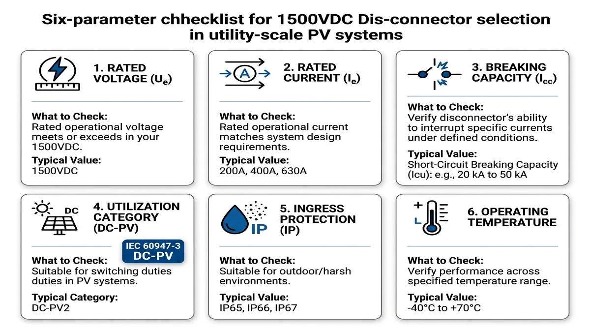
Selecting a 1500V DC isolator switch for utility-scale PV means verifying six core electrical and mechanical parameters before purchase. Missing any one of them can lead to failed isolation, rejected compliance reviews, or arc-related damage at the combiner or inverter input.
| 매개변수 | What to Check | Typical Utility-PV Value |
|---|---|---|
| Rated Voltage (Ue) | Must equal or exceed maximum open-circuit string voltage including temperature correction | 1500 VDC |
| Rated Current (Ie) | Continuous current capacity at maximum ambient; derate for enclosure temperature | 32 A – 1250 A depending on string/array level |
| Breaking Capacity (Icc) | DC short-circuit breaking current the disconnector can safely interrupt | 10 kA – 25 kA at 1500 VDC |
| 활용 범주 | Governs switching duty — DC-PV category required for photovoltaic applications | DC-PV (per IEC 60947-3) |
| Ingress Protection (IP) | Enclosure rating for outdoor combiner and tracker environments | IP65 minimum; IP66 for high-dust or coastal sites |
| 작동 온도 | Full-rated performance across ambient range without derating | −25°C to +60°C |
IEC 60947-3 defines the DC-PV utilization category specifically for photovoltaic disconnectors. A switch rated only for DC-21B or DC-22B is not qualified for PV string isolation because it lacks validation for PV-specific arc interruption conditions such as reverse current and capacitive discharge.
In one 120 MW ground-mount project in Inner Mongolia in 2023, non-DC-PV-rated disconnectors installed at the combiner level welded shut during a ground fault event, forcing replacement across three inverter blocks.
Breaking capacity has to be coordinated with upstream gPV 퓨즈 so the device never has to interrupt more than its rated fault level. In 1500V systems, prospective short-circuit current at the combiner busbar often reaches 15–20 kA, making 20 kA a practical minimum baseline for many utility-scale designs.
For a full coordination method across string, combiner, and inverter positions, see the DC isolator switch selection guide.
Even a correctly specified isolator can fail early if installation quality and maintenance discipline do not match the stress profile of utility PV sites.
Proper installation and scheduled maintenance directly affect both uptime and personnel safety. In utility-scale environments, isolators face thermal cycling, dust, humidity, and vibration from wind-loaded structures.
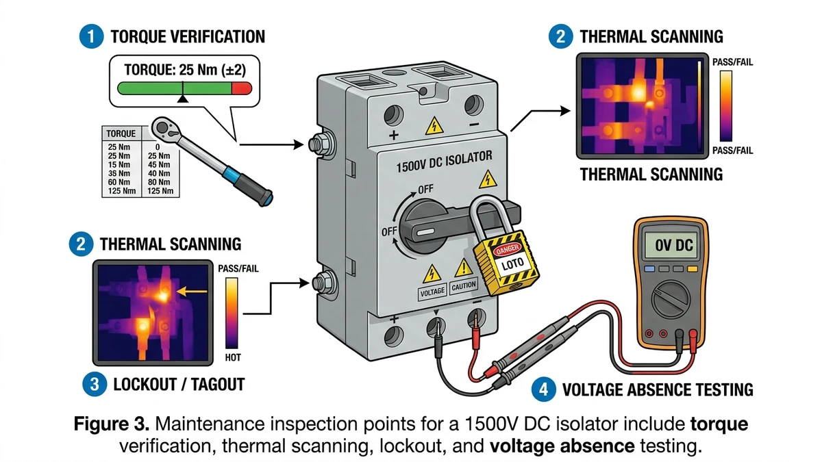
Correct termination torque is critical. Many 1500V DC isolator terminals specify about 8–12 N·m for busbar connections, with the exact value marked on the terminal or listed in the installation datasheet. Under-torqued terminations are a leading cause of resistive heating.
In a 120 MW ground-mount plant in Inner Mongolia in 2023, infrared surveys 90 days after commissioning found 14 isolator terminals running more than 85°C above ambient. Each case traced back to torque values below 6 N·m during rushed field assembly. After re-torquing and follow-up inspection, terminal temperatures returned to within 10°C above ambient.
Thermal imaging is best performed at commissioning, again at six months, and annually thereafter. Any hotspot with a temperature rise of 15°C or more relative to similar loaded adjacent terminals should be investigated immediately.
Lockout/tagout on 1500V DC circuits carries more residual risk than comparable AC work because stored energy in string capacitance can maintain hazardous conditions after the switch opens. The basic sequence is: open the isolator, verify absence of voltage at both line and load terminals with a CAT IV-rated meter, then apply the lock.
For string-level protection coordination, pairing the isolator with properly rated gPV fuses limits the fault stress seen by the contacts.
[Expert Insight]
– Re-torque sample terminals after the first thermal cycle period, especially on sites commissioned in hot, dusty seasons.
– Compare thermal images only across terminals carrying similar current; raw hotspot values without load context can mislead.
– Keep replacement handles, shaft couplers, and terminal hardware on site, not just spare switch bodies.
– Train crews to verify both line and load sides after opening, since backfeed assumptions are a common field error.
For export work, the electrical rating alone is not enough; the isolator also has to match the certification framework expected by the destination market, insurer, and AHJ.
On cross-border utility PV projects, choosing between IEC 60947-3 and UL 98B is usually driven by destination requirements rather than contractor preference. Misalignment can trigger customs delays, re-testing, or insurance objections.
A 120 MW ground-mount project in Xinjiang in 2023, built for a North African offtaker, required dual-certified isolators—IEC 60947-3 for EPC QA alignment and UL 98B for the financing bank’s insurance review. The resulting re-certification delay added about 11 weeks to the schedule, a preventable problem if standards mapping had been done during FEED.
| 매개변수 | IEC 60947-3 | UL 98B |
|---|---|---|
| Governing body | International Electrotechnical Commission | Underwriters Laboratories |
| Rated voltage ceiling | 최대 1500VDC | 최대 1500VDC |
| 활용도 카테고리 | AC-23B / DC-21B, DC-22B, DC-23B | Not category-based; rated by application type |
| Dielectric test voltage | 2× Ue + 1000 V (min 2500 V) | 2× rated voltage + 1000 V |
| Short-circuit withstand | Icu / Ics rated in kA | Withstand current in kA, per UL test protocol |
| Endurance (mechanical ops) | 1000–2000 cycles at rated load | 500 operations minimum under load |
| NEC 690 physical compliance | Not directly addressed | Requires visible blade or positive OFF indication per NEC 690.17 |
| Arc interruption test | DC load switching at rated Ue and Ie | DC interruption at 1.05× rated voltage |
| Pollution degree | PD2 / PD3 per IEC 60664-1 | Overvoltage Category per UL environment rating |
| Certification mark | CE / CCC | UL Listed mark |
Projects following NEC 690 add physical requirements beyond basic electrical test scope. NEC 690.17 requires the DC disconnect to be lockable in the open position and to provide a visible blade or positive OFF indication. UL 98B-listed devices are commonly built around those expectations, while IEC 60947-3 products may need added accessories or enclosure features to comply.
For export procurement, many tier-1 EPCs now request datasheets that reference both IEC 60947-3 utilization categories and UL 98B withstand ratings. The solar disconnect selection guide explains how to cross-reference those values, and IEC 60947-3 scope and utilization categories provides the standard reference point.
Most disconnect failures in the field start long before commissioning, with specification shortcuts that put the wrong device into the wrong duty.
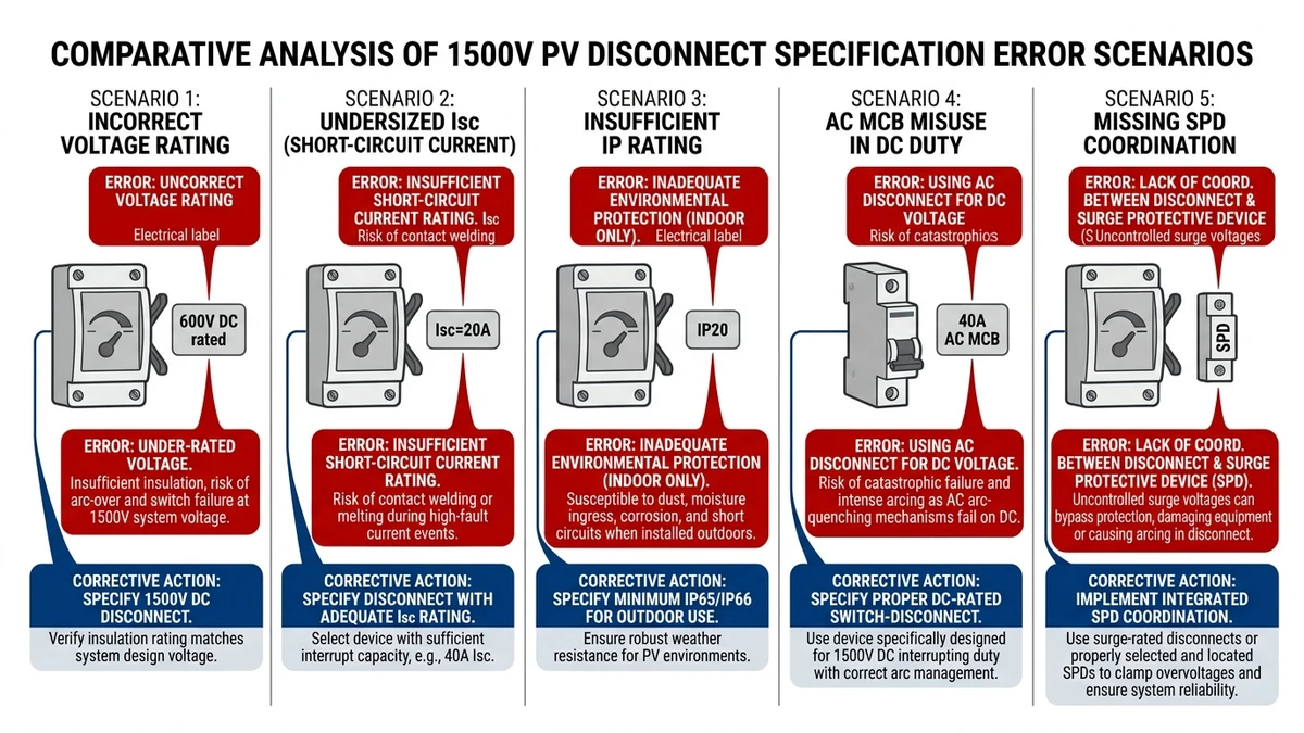
The recurring errors below show up regularly in commissioning reviews and compliance audits across utility-scale ground-mount projects.
| Error | 결과 | Corrective Action |
|---|---|---|
| Using a 1000V-rated disconnect in a 1500V string circuit | Dielectric breakdown under normal operating voltage; arc flash risk at contact gap | Verify Ue ≥ 1500 VDC on nameplate; confirm IEC 60947-3 or IEC 61010-1 DC voltage rating — not AC equivalent |
| Undersizing Isc rating below 2× string short-circuit current | Contact welding during fault; disconnect fails to open under load | Size for at least 1.25 × Isc per IEC 62548-1; for 1500V strings typically 12–18 A per string, select disconnect rated ≥ 25 A continuous |
| Ignoring IP rating for outdoor combiner box mounting | Moisture ingress causes tracking faults and insulation failure within 12–18 months | Specify minimum IP65 for outdoor enclosures; IP67 in coastal or high-humidity zones per IEC 60529 |
| Selecting AC-rated MCBs as DC disconnects | AC breakers lack magnetic arc blowout geometry for DC; arc sustains and burns contacts | Use purpose-built disconnectors with DC-specific arc chute design rated at 1500 VDC |
| Omitting surge coordination — no SPD upstream of disconnect | Transient overvoltages from lightning or switching exceed disconnect’s impulse withstand (Uimp); insulation degrades | Install coordinated surge protection devices upstream; align Uimp ≥ 8 kV per IEC 61643-31 for 1500V PV systems |
In one 120 MW ground-mount installation in Inner Mongolia in 2023, post-commissioning inspection found that about 15% of string disconnects had been substituted with AC-rated components during procurement. Replacement cost exceeded the original component budget by three times, and two units already showed erosion consistent with sustained DC arcing.
For deeper guidance on voltage matching and load-break duty, the DC isolator switch selection guide remains the key reference. Pairing the disconnect with correctly rated gPV fuses at combiner level closes the main fault-current gap.
To turn the technical criteria into a usable procurement workflow, apply the selection sequence below in order rather than treating ratings as a checklist to fill in later.
Verify the maximum open-circuit string voltage at the site’s lowest design ambient temperature. For 1500V architectures, the isolator should carry a rated voltage of at least 1500 VDC and a PV-appropriate DC utilization category under IEC 60947-3.
Add the string currents feeding the isolator and apply a 1.25× Isc design factor. For example, a combiner with 16 strings at 12 A Isc requires an isolator rated for at least 240 A continuous duty.
Use the system fault study to identify the prospective short-circuit current at the installation point. The isolator’s conditional short-circuit capability must meet or exceed that value, which is often in the 10–25 kA range in utility-scale DC distribution equipment.
Ground-mount sites generally require IP65 minimum, while desert or highly exposed environments often justify IP66. Match the enclosure to the site’s dust, rain, salt, and washdown exposure rather than using a default rating.
Check whether the plant uses an ungrounded or grounded DC design, since that affects whether a 2-pole or 4-pole isolator is needed. Then confirm the actual breaking capacity at 1500 VDC from the disconnector datasheet.
Confirm IEC 60947-3 or UL 98B compliance as required by the project, then verify coordination with upstream DC 퓨즈 and downstream DC 회로 차단기 through the project’s selectivity study. For a full standards-based walkthrough, the guide above covers the coordination logic in more detail.
If you need project-specific review, contact Sinobreaker’s technical team with system voltage, string Isc, and prospective short-circuit current data to get a pre-qualified isolator specification.
A 1500V device needs larger insulation distances, stronger arc control, and verified switching performance at a much higher DC energy level. It is not just a higher nameplate version of a 1000V part.
No. AC disconnects rely on current zero-crossing behavior that DC systems do not provide, so they are not suitable for sustained DC arc interruption.
Choose string-level isolation when fault localization, fast troubleshooting, and selective maintenance are priorities. Array-level isolation is more suitable when reducing device count matters more than per-string control.
IP65 is commonly treated as the minimum for outdoor utility PV use, while harsher dust, salt, or moisture exposure may justify IP66 or higher. The enclosure rating should match the actual environmental conditions at the site.
It shows the isolator has been evaluated for photovoltaic switching duty rather than generic DC loads. Without the right category, the switch may not safely interrupt the conditions seen in PV strings and combiners.
A practical schedule is at commissioning, after the first six months of operation, and then annually. Additional scans are useful after major maintenance, abnormal heating alarms, or repeated load issues.