주소
304 북쪽 추기경
세인트 도체스터 센터, MA 02124
근무 시간
월요일~금요일: 오전 7시~오후 7시
주말: 주말: 오전 10시 - 오후 5시
주소
304 북쪽 추기경
세인트 도체스터 센터, MA 02124
근무 시간
월요일~금요일: 오전 7시~오후 7시
주말: 주말: 오전 10시 - 오후 5시

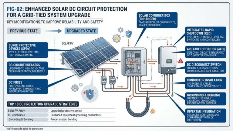
At the array level, a 6-string PV combiner box is the point where six parallel string circuits are consolidated, protected, and handed off as one controlled DC output to the inverter.
A 6-string PV combiner box aggregates the DC output of six parallel solar strings into a single feed to the inverter. It provides overcurrent protection per string, surge suppression, and a means of isolation, reducing wiring complexity while protecting the array against reverse current, arc-fault escalation, and transient overvoltages up to 1500 VDC.
In a typical ground-mount or rooftop PV system, each string generates roughly 8–12 A of short-circuit current in conventional module classes, though newer high-current modules can push design values higher after correction factors are applied. The combiner box collects these six strings at a common DC busbar, then routes the combined current through a main disconnect to the inverter input terminals.
Without string-level protection, a faulted string can receive reverse current from the remaining healthy strings, exceeding the module’s reverse current rating and creating a sustained fault condition. IEC 62548 governs PV array design requirements and requires string protection when the maximum possible reverse current is greater than the module’s permitted value.
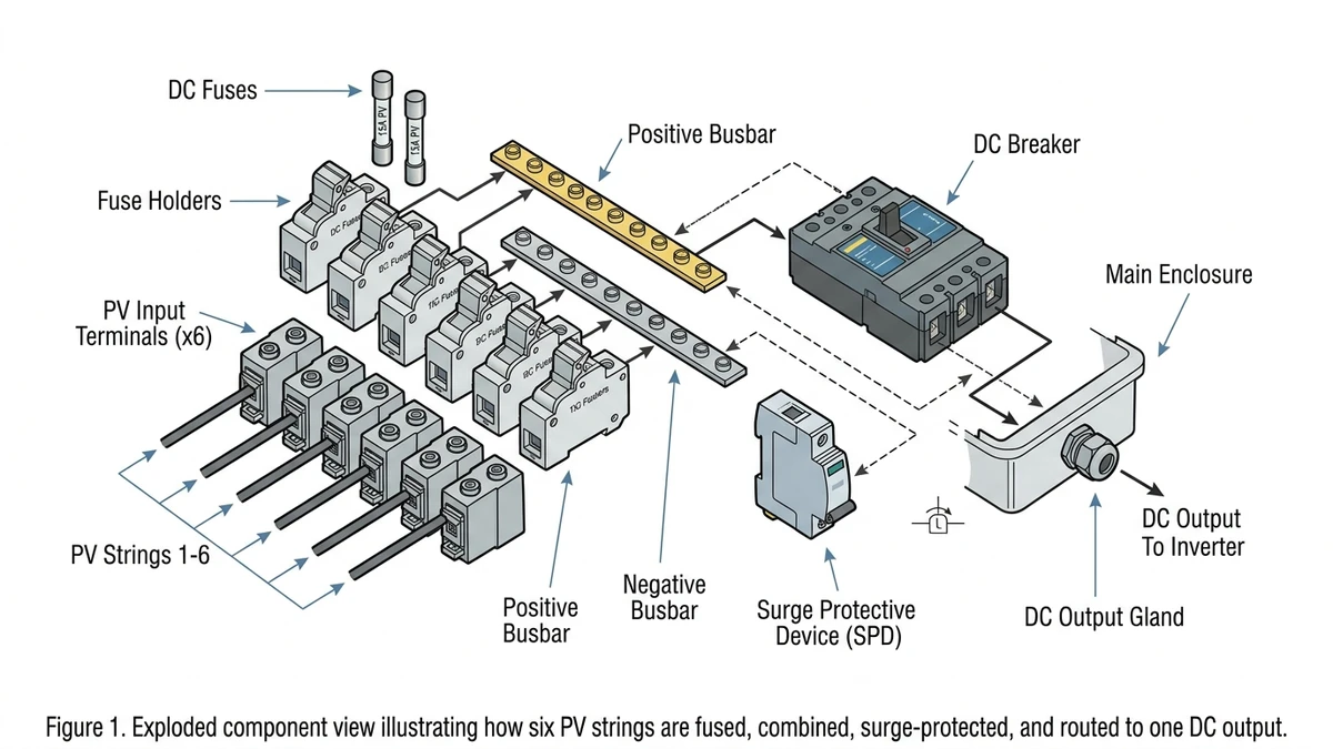
A properly specified 6-string PV combiner box typically includes:
In a 22 MW rooftop installation across industrial facilities in Zhejiang Province, field crews found that boxes with per-string protection isolated a bad string in under 3 minutes, while unfused layouts required broader shutdown and much longer troubleshooting.
Before you select enclosure size or protection hardware, lock down the electrical values that define whether the combiner will run safely under peak irradiance and worst-case temperature.
Sizing a 6-string PV combiner box correctly requires five calculations in sequence. The process below applies to both 1000 VDC and 1500 VDC architectures and is the fastest way to avoid undersized fuses, nuisance trips, and inspection failures.
Start with module datasheet Isc at STC, then apply the design correction factor required by your governing standard or project specification. For IEC-based design, a 1.25 multiplier is commonly used to account for elevated irradiance. If a module has Isc of 18.2 A, the design current becomes 22.75 A per string.
Each string fuse must be coordinated with both the corrected string current and the module’s maximum series fuse rating. Using the example above, a design current of 22.75 A requires a fuse that is high enough to avoid nuisance opening but still low enough to clear reverse-current faults before conductor or module damage occurs. Always verify the final fuse choice against the module datasheet.
Add the six string currents at the busbar. For 6 strings at 22.75 A each, the maximum output current is 136.5 A. The output DC protective device should then be selected with adequate continuous current margin.
The combiner voltage rating must exceed maximum string Voc under the lowest site temperature. Use the module’s temperature coefficient to correct Voc upward for winter conditions. For 1500 VDC systems, every relevant component, including fuses, disconnects, busbars, terminals, and enclosure insulation system, must carry a matching 1500 VDC rating. In a 32 MW ground-mount project in Inner Mongolia, nominally 1000 VDC combiners experienced repeated insulation failures once winter Voc rose beyond safe margin.
Calculate prospective short-circuit current (Ipsc) at the combiner output using the inverter’s DC input impedance and cable resistance. For a 1500 VDC string array with 6 parallel strings, Ipsc typically reaches 10–25 kA at the busbar. The output breaker’s rated ultimate breaking capacity (Icu) must meet or exceed this value — verified per IEC 60947-2.
Cross-check the final wiring path against the PV 컴바이너 박스 배선 가이드 before freezing the BOM, especially if the project may later scale to different string counts.
[Expert Insight]
– Check the module’s maximum series fuse value before ordering string fuses; that limit can override a simple current-window selection.
– Use minimum site temperature from project meteorological data, not annual average climate tables, when correcting Voc.
– If the output protective device is close to its frame limit, leave room for future module uprating or repowering.
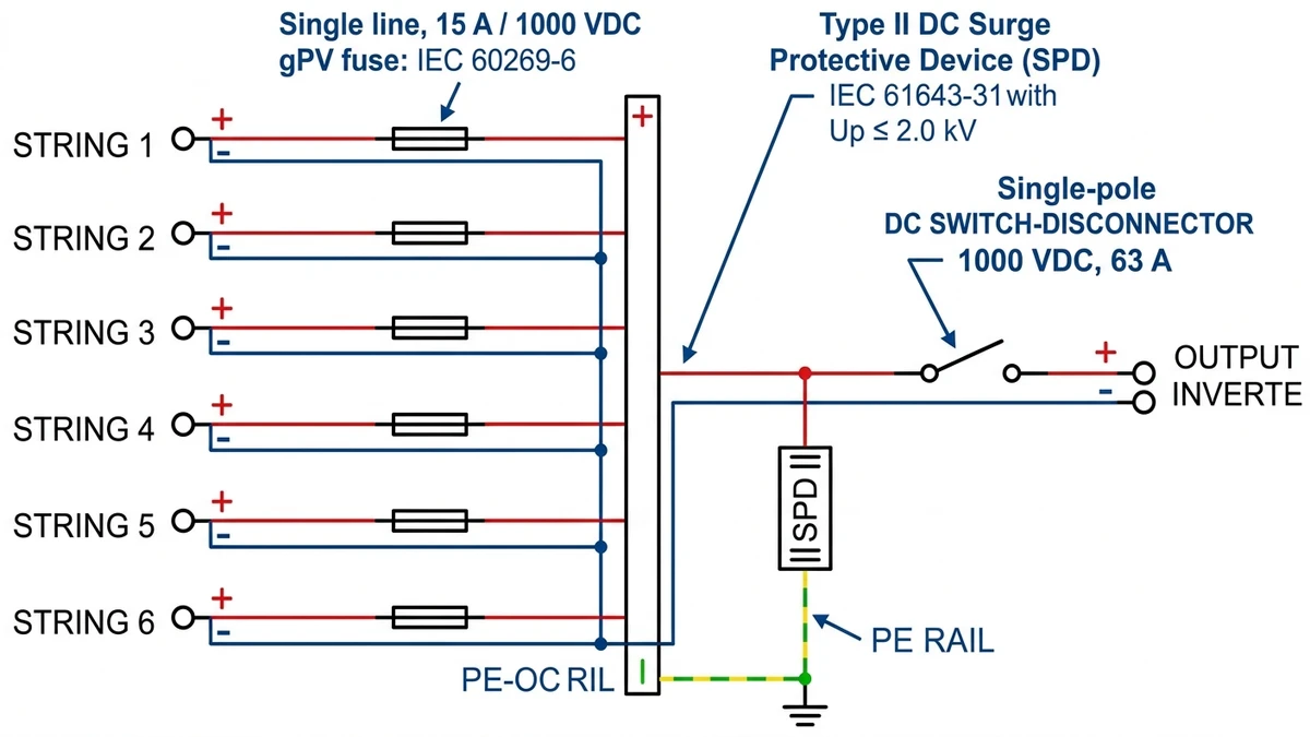
A numerical example makes the sizing logic easier to apply on site.
The array uses 6 strings of 8 × 400 W modules with Voc = 41.2 V and Isc = 9.85 A per module at STC. Strings are wired in series, then combined before feeding a 15 kW inverter.
Each string requires a gPV fuse rated above 12.3 A but still within the module’s maximum series fuse limit. A 15 A, 1000 VDC gPV fuse is appropriate for this case.
The combiner output should be protected by a DC circuit breaker rated for at least the 73.9 A design output current. An 80 A, 1000 VDC DC MCCB with breaking capacity of 10 kA or higher is a practical selection for this array size.
| 매개변수 | Calculated Value | Selected Rating |
|---|---|---|
| String Voc (corrected) | 363.2 V | 1000 VDC components |
| Design Isc per string | 12.3 A | 15 A gPV fuse |
| Combined design current | 73.9 A | 80 A DC MCCB |
| String count | 6 | 6-string combiner box |
| Combiner voltage rating | 363.2 V | 1000 VDC |
In a 12 MW rooftop installation across commercial warehouses in Zhejiang Province, applying the corrected Isc value during fuse selection eliminated summer nuisance blowing that had occurred when fuses were chosen too close to nominal module current.
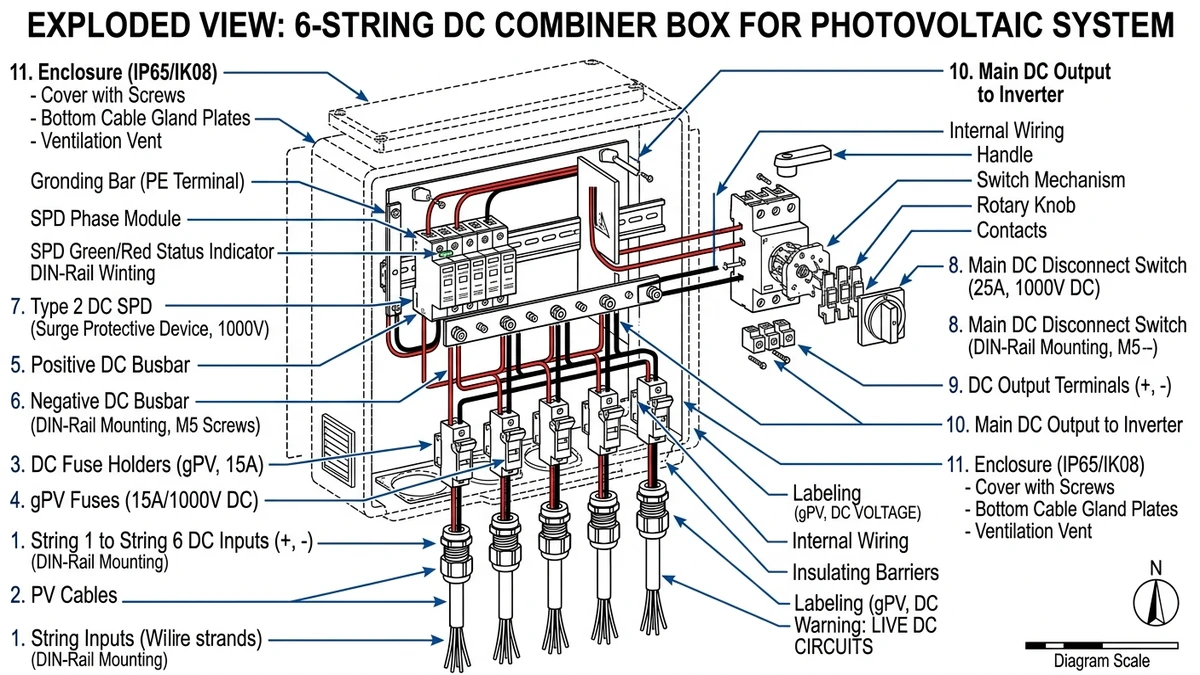
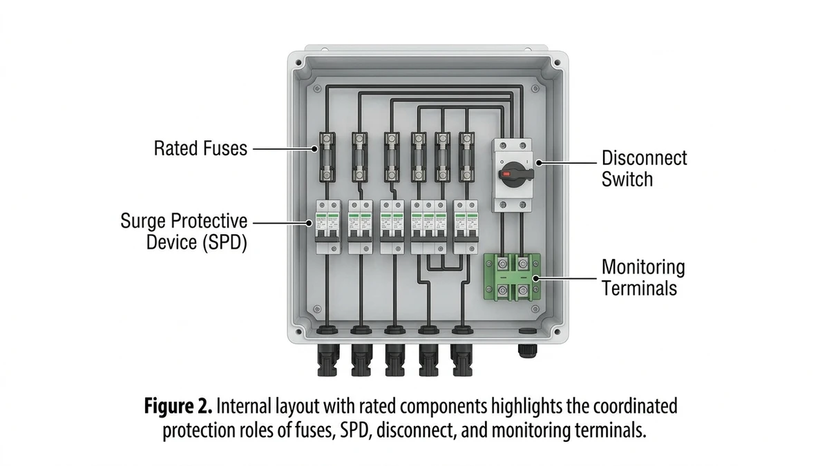
A 6-string PV combiner box is a coordinated protection assembly, not just a junction enclosure. Each component has a separate electrical role and a distinct failure mode.
Each string input passes through a dedicated gPV fuse, commonly in the 10–15 A range for lower-current modules and higher where modern module currents require it. These fuses are governed by IEC 60269-6 and are intended specifically for PV reverse-current protection. If the fuse is undersized relative to corrected Isc, it can open during normal irradiance peaks; if oversized, it may not clear a reverse-current fault quickly enough.
The combiner output passes through a DC-rated main disconnect, either a switch-disconnector or an MCCB, sized for the combined current and system voltage. This device provides isolation for maintenance and, when properly selected, can also handle fault interruption at the required breaking capacity. In higher fault-current installations, a DC MCCB is usually the safer choice over a simple isolator.
The SPD clamps lightning-induced or switching-induced overvoltage and is connected across the DC bus rather than in series with load current. For PV applications, Type II DC SPDs built to IEC 61643-31 are standard in many exposed rooftop and ground-mount sites. A degraded MOV can lose clamping performance over time, so SPD condition indicators should be part of maintenance inspection.
Some combiner boxes include string-level monitoring terminals tied to a logger or SCADA input. These allow technicians to compare string currents and identify weak strings before they trigger protective devices.
[Expert Insight]
– Replace any SPD with a failed status window immediately; a healthy-looking enclosure does not mean the MOV is still protective.
– Re-torque busbar and fuse-holder terminations after initial thermal cycling if the manufacturer requires it.
– Keep spare fuse links of the exact installed rating in the O&M kit; emergency substitutions often create coordination problems.
Most combiner box problems appear after energization, but the root cause is usually a preventable commissioning error.
Installing a fuse based on nominal string current instead of corrected design current is one of the most common mistakes. A string producing 10 A Isc does not justify a 10 A fuse in a PV combiner. In a Hebei ground-mount project, this error caused repeated daytime string outages until undersized fuses were replaced.
A single reversed input can force abnormal current through adjacent string protection and create hidden damage before the issue is noticed in production data. Always verify polarity at string tails, at combiner entry, and again at the busbar before final energization.
Loose busbar terminations are a leading cause of internal heating. Elevated contact resistance at aggregate current can create hotspots severe enough to damage insulation, discolor copper, and trip the output DC protective device. Use the manufacturer’s torque value for every terminal and verify with a calibrated tool rather than hand feel.
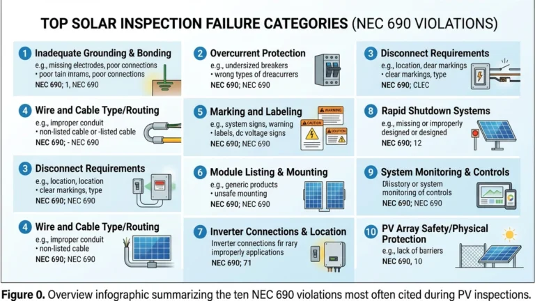
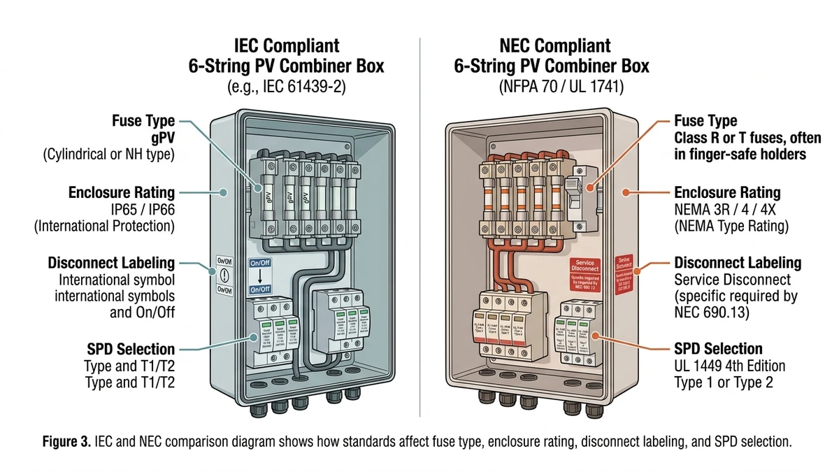
Compliance affects more than paperwork; it changes hardware selection, enclosure marking, and what inspectors expect to see in the field.
| 요구 사항 | IEC Framework | NEC Framework |
|---|---|---|
| Governing document | IEC 62548 (PV array design) | NFPA 70 Article 690 |
| String fuse standard | IEC 60269-6 (gPV fuse) | UL 2579 |
| Enclosure protection | IP65 minimum typical | NEMA 3R or 4X equivalent |
| Max system voltage | 1500 VDC | 1500 VDC |
| Disconnect requirement | IEC 60947-3 load-break switch | NEC 690.15 accessible DC disconnect |
| SPD standard | IEC 61643-31 | UL 1449 |
| Monitoring/alarm | Often project-specified | Rapid shutdown and labeling may apply |
IEC-based projects generally focus on array design rules, isolation, and product conformity. NEC-based projects add more prescriptive requirements around labeling, shutdown behavior, and listing for North American acceptance.
In the United States, the Authority Having Jurisdiction can impose requirements beyond the base NEC language, especially for labeling, disconnect accessibility, and product acceptance. In export markets across Southeast Asia and the Middle East, IEC compliance is often the baseline, but utility or national grid rules may still add local conditions.
A 22 MW project in Shandong faced inspection delays because the combiner design met IEC electrical expectations but did not include the labeling package required by the buyer’s North America-style compliance documents. For NEC reference, see https://www.nfpa.org.
String count selection is a field layout decision as much as an electrical one, because it influences conduit runs, enclosure size, and maintenance workflow.
| 매개변수 | 4-String | 6-String | 8-String |
|---|---|---|---|
| Typical inverter MPPT range | 200–600 VDC | 600–1000 VDC | 1000-1500 VDC |
| Max combined string current | 40–60 A | 60–90 A | 80–120 A |
| Cable runs to inverter | 4 pairs | 6 pairs | 8 pairs |
| Enclosure footprint | Small | Medium | Large |
| Fuse/breaker count | 4 | 6 | 8 |
| Relative BOM cost | 낮음 | 보통 | 더 높음 |
| Best fit | Small rooftop | Commercial rooftop, 50–250 kW | Ground-mount, >250 kW |
A 6-string combiner box is usually the best fit for commercial rooftop systems where installers want to consolidate field wiring without driving bus current too high for standard enclosure and disconnect sizes. In a 120 kW rooftop project across three commercial buildings in Zhejiang Province, engineers standardized on 6-string boxes to keep output current below about 75 A while cutting conduit runs versus a 4-string layout.
A 4-string box is often better for small arrays or sites with limited roof zoning. An 8-string box becomes more attractive in large ground-mount fields where reducing trenching and home-run count offsets the larger enclosure and higher-rated switching hardware. If the site is likely to expand later, choose a string count that leaves practical margin in inverter input planning and maintenance access.
With sizing, protection roles, and configuration choices established, specification becomes a short checklist of values that should be verified before ordering.
If those items are confirmed, move on to component-level selection and documentation. The gPV fuse series covers string protection options up to 1500 VDC, and the PV combiner box range includes pre-configured 6-string assemblies with optional monitoring.
For installation sequence and termination details, use the PV 컴바이너 박스 배선 가이드. If string-count tradeoffs are still under review, the combiner box selection guide provides a broader comparison across common array sizes.
It combines six PV strings into one DC output while adding string-level protection, surge control, and isolation for safer inverter connection.
Use the string’s design current after applying the required correction factor, then confirm the selected fuse does not exceed the module’s maximum series fuse rating.
Yes, but only if every internal component, including fuses, disconnects, SPD, terminals, and insulation system, is rated for 1500 VDC service.
In most practical parallel-string PV designs, yes, when reverse current from the other strings could exceed the module’s allowable limit.
It can damage protection devices, create abnormal current paths, and leave the array with a hidden fault that is harder to diagnose later.
For outdoor PV installations, it is commonly required or strongly recommended because long DC cable runs are vulnerable to lightning-induced surges.
Use 6-string when you need a middle-ground option that reduces cable runs and enclosure count without pushing current and hardware size into larger utility-scale territory.