주소
304 북쪽 추기경
세인트 도체스터 센터, MA 02124
근무 시간
월요일~금요일: 오전 7시~오후 7시
주말: 주말: 오전 10시 - 오후 5시
주소
304 북쪽 추기경
세인트 도체스터 센터, MA 02124
근무 시간
월요일~금요일: 오전 7시~오후 7시
주말: 주말: 오전 10시 - 오후 5시

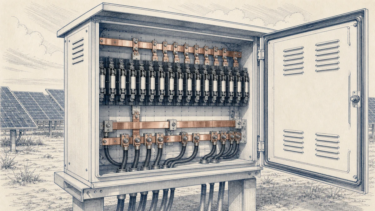
PV combiner boxes are expected to carry DC string current safely for long periods under high irradiance, high enclosure temperature, and repeated daily current cycling. In that environment, the fuse link is only one part of the protection system. The DC fuse holder, its terminals, its spacing, and the ventilation around it all influence the final operating temperature.
For Sinobreaker DC Fuse applications, fuse holder thermal derating should be treated as a design check, not an afterthought. A fuse may be correctly selected by voltage and current rating, but still operate too hot if the combiner box has poor airflow, tightly packed holders, undersized conductors, or terminal ratings that limit the allowable ampacity.
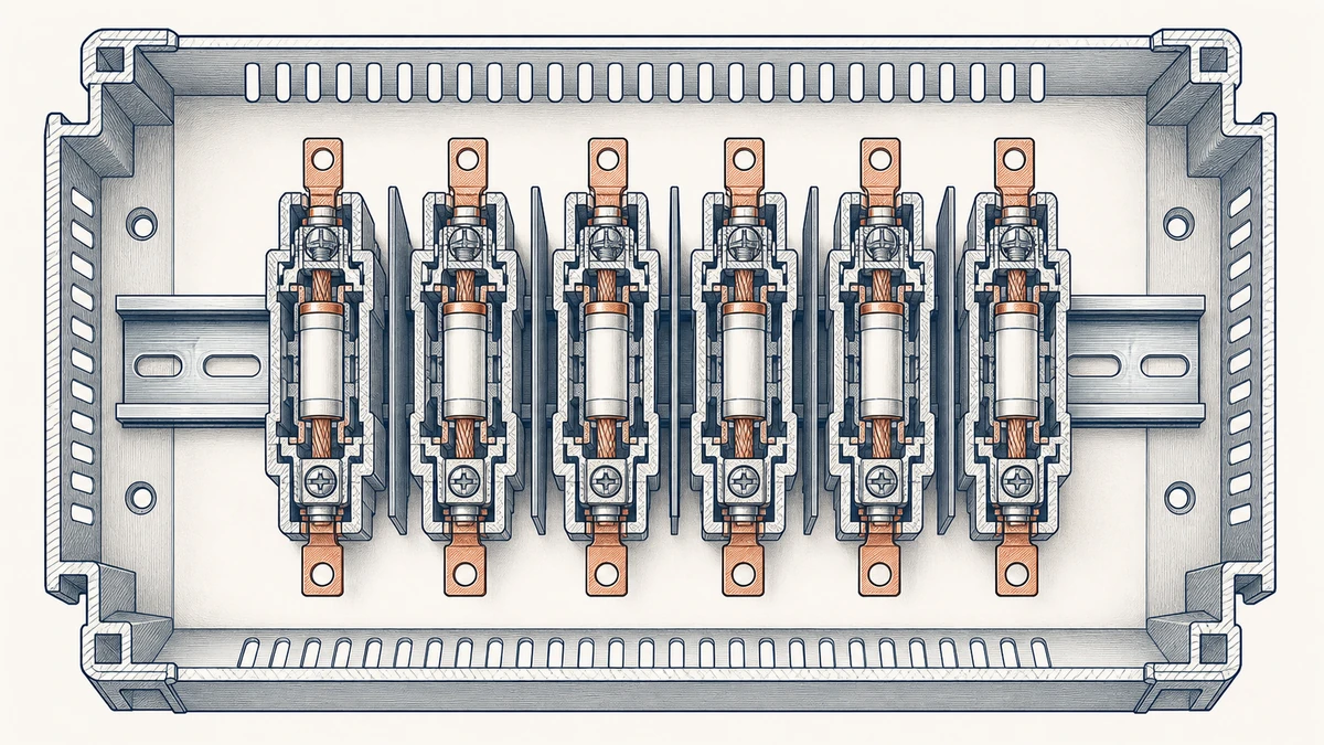
PV systems create a demanding thermal profile. During peak sunlight, current can remain near the expected maximum for hours. At the same time, outdoor enclosures may sit in direct sun, raising internal temperature above the surrounding ambient air. Inside a combiner box, multiple DC fuse holders installed side by side can further concentrate heat.
Fuse holder thermal derating is the process of adjusting the usable current capacity of the fuse-holder assembly according to real installation conditions. These conditions include:
The objective is simple: keep the DC fuse holder, fuse link, terminals, and connected conductors within their safe thermal limits during normal operation.
PV fuse nameplate ratings are established under controlled test conditions. A printed current rating does not mean the fuse will carry that current indefinitely in every enclosure, at every temperature, and in every mounting arrangement.
High ambient temperature can accelerate fuse-element heating. If this additional heat is not considered, the fuse may open earlier than intended, causing nuisance interruptions. In a PV combiner box, this can appear as repeated string fuse operation even when there is no downstream fault.
For this reason, the applicable correction factors from the fuse or fuse-holder manufacturer must be included in the selection process. The correction factor is not only about avoiding nuisance opening; it also helps confirm that the complete DC Fuse assembly remains thermally stable.
A DC fuse holder is not a passive plastic accessory. It contains conductive clips, terminals, contact springs, insulation materials, and heat-transfer paths. Each of these components contributes to operating temperature.
Heat is generated by:
If the holder is selected only by voltage class and fuse size, the thermal behavior of the assembly may be missed. In a PV combiner box, the holder must be checked under realistic current, temperature, and airflow conditions.
Thermal derating is usually not caused by one single factor. It is the result of several small heat sources combining inside a restricted enclosure.
A fuse holder installed at 25°C has more thermal margin than the same holder installed inside a combiner box operating at 55°C, 65°C, or higher. The higher the ambient temperature around the holder, the less room remains for current-generated heat rise.
For outdoor PV equipment, designers should distinguish between:
The most important value for derating is not always the weather-station ambient. It is the temperature experienced by the fuse-holder assembly inside the installed enclosure.
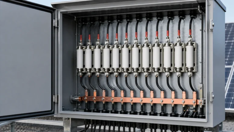
In a combiner box, fuse holders are often installed in rows. When many strings operate at the same time, each energized holder releases heat. The outer holders can dissipate heat more easily, while the central holders receive heat from both sides.
This means the center fuse holders may run hotter than the end positions even when all strings carry similar current. In dense installations, central positions should be treated as the thermal worst case.
Spacing fuse holders with an air gap can improve heat dissipation. However, multi-holder correction factors are installation guidance, not universal constants. Actual performance depends on enclosure size, airflow path, mounting orientation, current level, and the thermal characteristics of the selected DC Fuse holder.
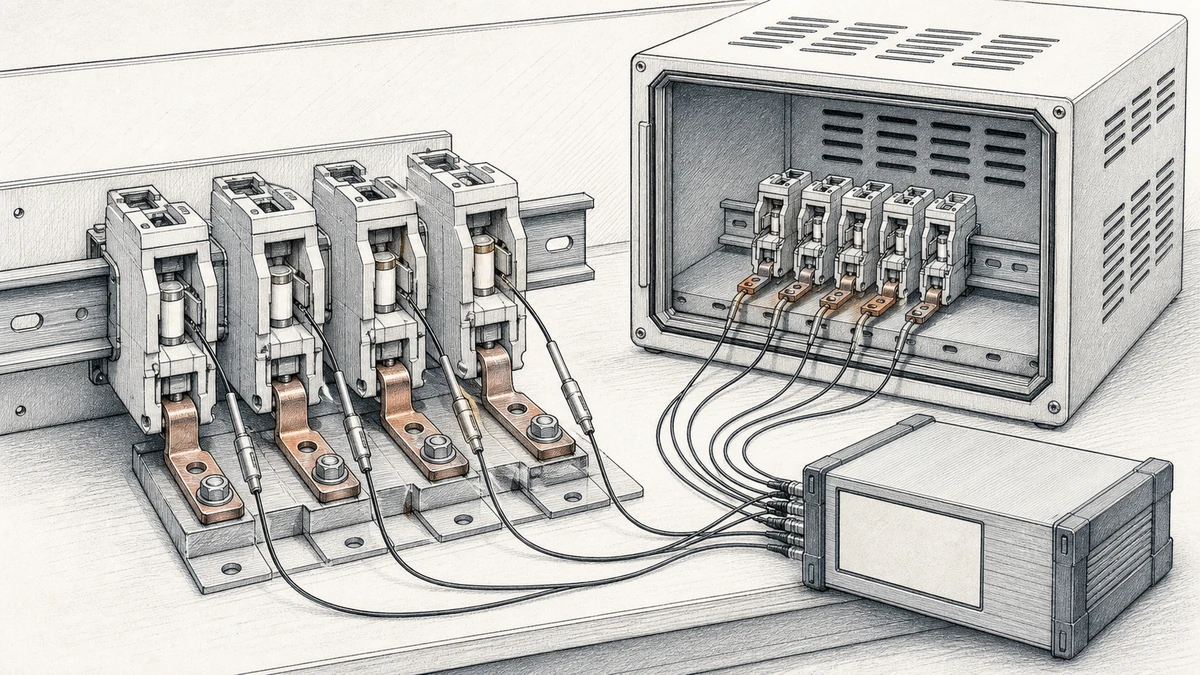
A fuse holder in open air cools differently from one inside a sealed PV combiner box. Enclosure restriction affects both convection and radiation. If warm air cannot move away from the holder, heat accumulates around the fuse body and terminals.
Thermal risk increases when the enclosure has:
For sealed outdoor combiner boxes, thermal evaluation should assume restricted airflow unless the enclosure design has been tested or modeled otherwise.
PV current changes through the day. Morning ramp-up, midday peak, cloud transients, and evening decline all create current cycling. While short transients may not fully heat the fuse holder, long periods of high current can create steady-state thermal stress.
The key design question is whether the holder reaches a safe steady-state temperature at the expected high-current condition. A short bench check may not reveal the final operating temperature. For high-temperature PV applications, the fuse-holder assembly should be evaluated after enough time has passed for the enclosure, conductors, terminals, and fuse body to stabilize.
Terminal temperature rating is one of the most commonly overlooked limits in DC Fuse holder selection. A conductor may have insulation rated for a higher temperature, but the connected fuse-holder terminal may be rated lower. In that case, the terminal rating can limit the usable conductor ampacity.
A proper fuse holder thermal derating review should include terminal temperature data. The check should confirm:
If the conductor insulation is rated 90°C but the holder terminal is rated for 75°C conductors, the design must respect the terminal limitation. Using a higher-temperature cable does not automatically increase the allowable current through the fuse holder terminal.
Even when the holder is correctly rated, poor termination quality can raise temperature. A loose screw, incomplete conductor insertion, oxidized conductor surface, or incorrect ferrule can increase contact resistance. In DC applications, this heat can remain localized at the terminal and may not be obvious during visual inspection.
Good practice includes:
For Sinobreaker DC Fuse installations, the terminal should be treated as a functional thermal component, not merely a mechanical connection point.
Ventilation does not always mean adding vents to the enclosure. In PV combiner boxes, it also means providing enough internal space for heat to move away from the fuse holders.
When fuse holders are mounted directly side by side, each unit limits the cooling surface of the adjacent unit. Adding an air gap can improve heat dissipation, especially for holders in the center of the row.
A spacing strategy should consider:
If space is limited, designers should avoid assuming that all holder positions behave the same. The central positions normally deserve closer thermal review.
Heat naturally rises. The orientation of the holder, wiring, and enclosure can influence how warm air moves around the fuse row. A layout that traps hot air near terminals may increase local temperature, while a layout that allows vertical heat movement may improve cooling.
Useful design considerations include:
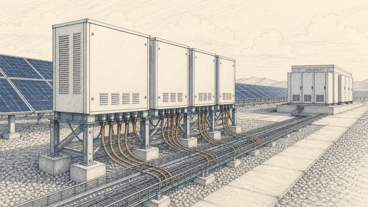
PV combiner boxes often require high ingress protection for outdoor use. Open ventilation may not be acceptable in dusty, wet, coastal, or industrial environments. Therefore, the thermal design must balance cooling with environmental protection.
Possible approaches include:
The correct solution is not always to add vents. Often, the better solution is to derate correctly and design the internal layout with thermal margin.
A consistent workflow helps prevent mistakes when selecting DC fuse holders for PV combiner boxes.
Start with the basic PV string data:
The fuse and fuse holder must be suitable for the system voltage and DC fault conditions before thermal derating is considered.
Next, define the temperature conditions. Avoid using only the nominal outdoor ambient if the enclosure will operate hotter internally.
Record or estimate:
For conservative design, use the highest credible internal operating temperature around the fuse holders.
Apply the relevant fuse and fuse-holder correction factors for ambient temperature, grouping, holder arrangement, and installation method. These factors should come from the applicable product documentation.
The corrected usable current capacity should remain above the expected continuous operating current with suitable design margin. If not, consider:
Confirm that the selected conductor ampacity is permitted by the fuse-holder terminal rating. The conductor insulation rating alone is not enough.
Check:
This step is essential because a thermally acceptable fuse body does not guarantee a thermally acceptable terminal.
In a multi-holder combiner arrangement, validate the likely hottest fuse holder position. This is often a central holder with energized holders on both sides.
Validation may include:
A useful test should allow enough time for temperature stabilization. Short-duration testing may understate terminal and enclosure heat rise.
Thermal derating is easier to manage when the combiner box is designed with heat flow in mind from the beginning.
For DC Fuse holder rows in PV combiner boxes:
The goal is to reduce local hot spots and make the thermal behavior more predictable.
When selecting a Sinobreaker DC Fuse solution, review the fuse and holder together as a system. Confirm that the assembly supports:
Selection should be based on the installed condition, not only the catalog rating.
Thermal performance can change after installation due to conductor movement, torque relaxation, contamination, or enclosure changes. Inspection helps confirm that the original design assumptions remain valid.
Useful inspection actions include:
Repeated nuisance opening should not be treated as only a fuse-sizing problem. It may indicate excessive holder temperature, poor ventilation, high terminal resistance, or incorrect derating.
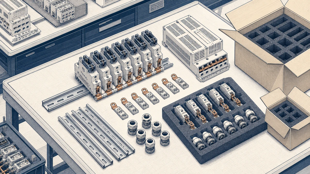
The most common mistake is selecting a fuse holder by nameplate current only. In a hot PV combiner box, the usable current may be lower than the printed value once ambient temperature, grouping, and enclosure restriction are considered.
In a row of adjacent holders, the center position may operate hotter than the ends. If the design only checks an outside position, it may miss the true worst case.
A 90°C conductor does not override a lower terminal temperature rating. The fuse-holder terminal data must be included in the ampacity and thermal selection check.
Ventilation and spacing should be part of the initial combiner design. Once the enclosure is crowded, it may be difficult to create a reliable cooling path without changing the layout or derating the circuit.
Fuse holder thermal derating means reducing or verifying the usable current capacity of the fuse-holder assembly according to actual installation conditions. In PV combiner boxes, those conditions include high ambient temperature, restricted enclosure airflow, adjacent energized holders, terminal temperature limits, and long periods of continuous DC current.
Adjacent fuse holders transfer heat into nearby positions. In a row of energized holders, the center units receive heat from both sides and usually have less cooling surface exposed to free air. This can make the central fuse holders the thermal worst case, especially in compact PV combiner boxes with limited ventilation.
Not by itself. A higher-temperature conductor may provide more cable insulation margin, but the fuse-holder terminal rating can still limit allowable ampacity. The conductor, terminal, fuse holder, fuse link, enclosure, and ambient temperature must be checked together.
Fuse holder thermal derating is essential for reliable DC Fuse performance in PV combiner boxes. High ambient temperature, restricted ventilation, adjacent fuse holders, terminal ratings, and current cycling all affect the final operating temperature.
For Sinobreaker DC Fuse applications, the best approach is to evaluate the fuse and holder as one installed system. Apply the relevant correction factors, check terminal and conductor limits, allow for enclosure heat rise, and validate the hottest holder positions. A properly derated design reduces nuisance opening, protects terminals and conductors, and improves long-term PV combiner box reliability.