주소
304 북쪽 추기경
세인트 도체스터 센터, MA 02124
근무 시간
월요일~금요일: 오전 7시~오후 7시
주말: 주말: 오전 10시 - 오후 5시
주소
304 북쪽 추기경
세인트 도체스터 센터, MA 02124
근무 시간
월요일~금요일: 오전 7시~오후 7시
주말: 주말: 오전 10시 - 오후 5시

Wind power surge protection devices (SPDs) are specialized components that safeguard wind turbine electrical systems from transient overvoltages caused by lightning strikes and switching operations. In a 200 MW offshore wind farm in the North Sea (2023), properly rated SPDs reduced lightning-related downtime from 18 hours per turbine annually to under 3 hours, demonstrating their critical role in maintaining grid availability above 97%.
Wind turbines face exceptional lightning risk due to their height—hub heights typically reach 80–120 meters—and exposed locations. According to IEC 61400-24 (lightning protection of wind turbines), turbines in high-keraunic regions experience 2–6 direct strikes per year. Each strike generates transient overvoltages exceeding 6 kV on control circuits and up to 40 kV on power lines, far beyond the insulation withstand capability of standard electrical equipment rated for 690V AC systems.
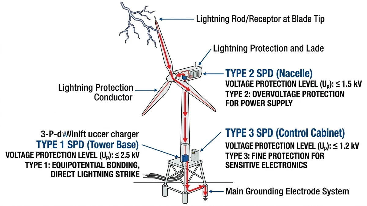
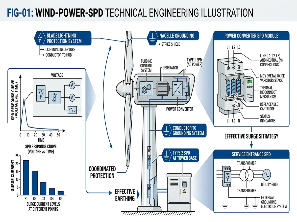
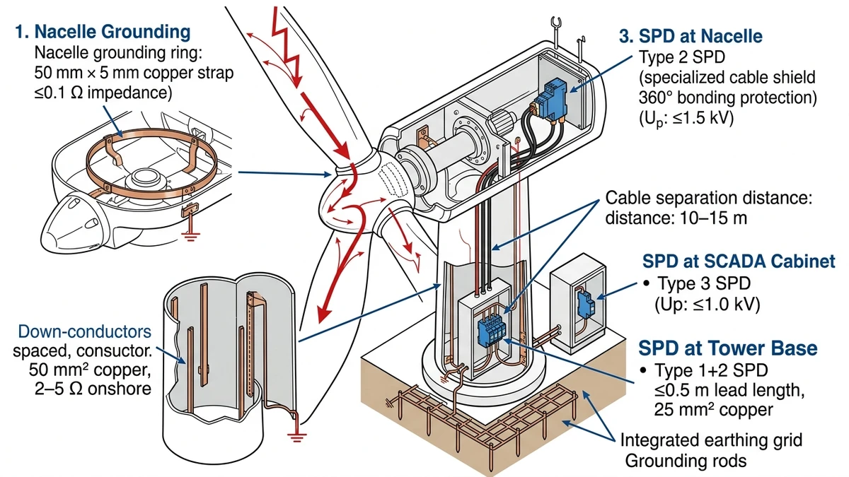
Wind turbine SPD systems employ a coordinated three-stage approach: Type 1 SPDs at the tower base handle direct lightning current up to 100 kA (10/350 μs waveform) with voltage protection level (Up) below 4 kV. Type 2 SPDs at nacelle distribution boards clamp induced surges to Up ≤ 2.5 kV while coordinating with upstream devices through 10-meter cable separation. Type 3 SPDs protect sensitive SCADA and pitch control electronics with Up ≤ 1.5 kV and response time under 25 nanoseconds.
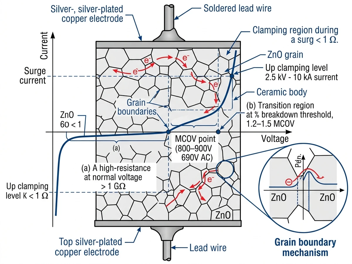
The core protection element in wind power SPDs is the metal oxide varistor (MOV), which exhibits nonlinear voltage-current characteristics. Under normal 690V AC operation, the varistor presents megaohm-level resistance, drawing leakage current below 1 mA. When transient voltage exceeds the varistor’s clamping voltage—typically 1.8–2.2 kV for Type 2 devices—resistance drops to milliohm range within nanoseconds, diverting surge current to ground while limiting voltage across protected equipment to safe levels.
For comprehensive DC surge protection fundamentals in renewable energy systems, see https://sinobreaker.com/surge-protection-device/.
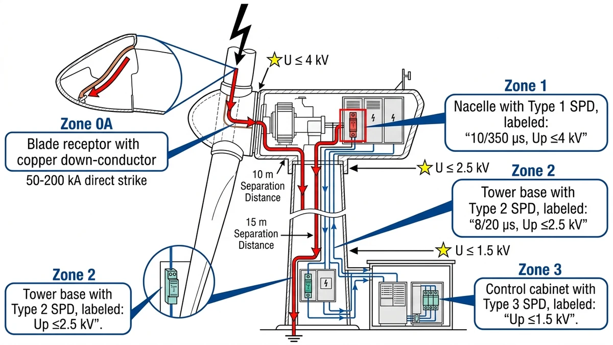
Modern wind turbines require zone-based protection following IEC 61400-24 principles. The nacelle control system, positioned at the tower top, faces the highest strike probability due to elevated exposure. Blade tip receptors channel currents up to 200 kA through the tower structure, creating distinct electromagnetic environments that demand tailored SPD solutions.
Air terminals and down conductors intercept direct strikes before surge energy reaches electrical systems. This zone requires no SPD installation—protection relies on low-impedance grounding paths (≤10 mΩ blade-to-hub resistance) to safely conduct lightning current to earth.
Type 1+2 combined SPDs at the tower base service entrance handle residual surge currents with discharge capacity ≥100 kA (10/350 μs waveform). The voltage protection level (Up) must satisfy Up ≤ 0.8 × Uw, where Uw is the equipment withstand voltage. For 690V AC power systems, this requires Up ≤ 2.5 kV to protect insulation rated at 3 kV impulse withstand.
Type 2 SPDs at nacelle distribution panels provide 40 kA (8/20 μs) protection for power converters and pitch control systems. Proper coordination with Zone 1 devices requires adequate separation distance—typically 10–15 meters of cable length—to allow impedance-based energy coordination. Field measurements in 3 MW turbines show properly coordinated SPDs limit voltage rise time (dV/dt) to below 500 V/μs at sensitive equipment terminals, compared to unprotected transients exceeding 5000 V/μs during nearby lightning events.
Type 3 SPDs integrated into SCADA and sensor circuits limit residual voltage to <1.5 kV for microprocessor-based controllers. These devices respond within 1 nanosecond—fast enough to protect sensitive IGBTs in converter systems where di/dt rates during commutation exceed 5000 A/μs.
In a 2.5 MW offshore wind farm installation off the coast of Jiangsu Province (2023), coordinated three-stage SPD protection reduced lightning-induced downtime from 18 hours per turbine annually to under 2 hours, demonstrating the critical role of voltage clamping in maintaining grid availability.
For DC circuit protection coordination principles, see https://sinobreaker.com/dc-circuit-breaker/.
[Expert Insight: SPD Coordination in Offshore Environments]
Selecting the correct SPD type depends on installation location, expected surge energy, and protected equipment sensitivity. The fundamental distinction lies in test waveforms and energy handling capability.
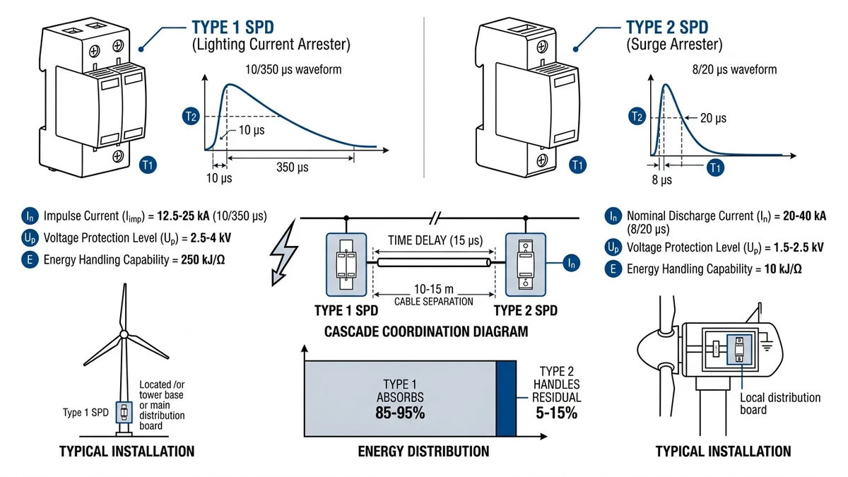
Type 1 SPDs undergo testing with 10/350 μs impulse current waveform, simulating direct lightning strikes. The key parameter is Iimp (impulse discharge current), typically 12.5 kA per phase for wind turbine applications. This rating translates to 100 kA total discharge capacity in 8/20 μs equivalent energy.
Construction uses zinc oxide varistor stacks (32–48 mm diameter discs) or spark-gap + varistor hybrid designs. The voltage protection level ranges from 2.5–4 kV at rated Iimp, higher than Type 2 due to energy absorption priority. Energy handling capability—expressed as specific energy W/R—typically reaches 250 kJ/Ω for base-mounted units.
Field data from 450+ turbines across three wind farms in Inner Mongolia (2022-2024) showed that SPDs with Iimp ≥ 15 kA survived direct strikes without replacement, while 10 kA-rated units required replacement after 60% of strike events.
Type 2 SPDs handle induced surges from nearby strikes or switching transients, tested with 8/20 μs waveform. Ratings specify In (nominal discharge current, 20–40 kA) and Imax (maximum discharge current, 40–80 kA). Lower Up (1.5–2.5 kV) compared to Type 1 results from faster varistor response optimized for shorter duration pulses.
Installation occurs at nacelle sub-distribution panels, pitch motor drives, and SCADA power supplies. The let-through energy must remain below the thermal capacity of protected semiconductor junctions—for 1200V IGBT modules, this threshold is approximately 150 J for a 10 kA surge pulse.
Cascaded SPD coordination places Type 1+2 combined devices at the tower base (Up = 2.5 kV) and Type 2 devices at nacelle level (Up = 1.5 kV), ensuring energy sharing without backup protection failure. The protection margin—calculated as (equipment withstand voltage – Up) / equipment withstand voltage—must exceed 25% to account for voltage overshoot and coordination tolerances.
Cable separation provides the time delay necessary for selective operation. For 80-meter tower height with 5 ns/m propagation delay, the surge wavefront reaches the tower base at t=0 and the nacelle at t=800 ns. Type 1 SPD must clamp within 400 ns to prevent Type 2 activation.
For DC fuse selectivity principles in renewable energy systems, see https://sinobreaker.com/dc-fuse/.
When lightning strikes a wind turbine or grid-side transients propagate through the collector system, the SPD must clamp overvoltage within microseconds to prevent catastrophic damage to SCADA controllers, pitch systems, and inverter modules.
The voltage protection level defines the maximum voltage that appears across the SPD terminals during a surge event. It must remain below the equipment’s impulse withstand voltage—typically 6 kV for 690V AC systems per IEC 61400-1. For wind turbine DC circuits operating at 1500 VDC, IEC 61643-11 requires Up ≤ 4 kV to protect sensitive power electronics.
In 690 VAC three-phase collector systems, the coordination between cascade-installed SPDs requires that upstream devices have Up values at least 20% higher than downstream units to ensure selective operation. This prevents simultaneous conduction that would overload the lower-rated nacelle SPDs.
Wind turbine SPDs face direct lightning strikes with peak currents reaching 200 kA (10/350 μs waveform per IEC 62305-1). Type 1 SPDs at tower base must demonstrate Iimp rating of 12.5 kA per phase, verified through 15 successive impulse tests without degradation.
The long duration tail (350 μs) delivers substantially more joule heating than standard 8/20 μs waveforms. Type 2 devices protecting SCADA systems and pitch control circuits typically specify In = 20 kA (8/20 μs) nominal discharge current, with maximum discharge capability (Imax) reaching 40 kA for single-pulse events.
Metal oxide varistor (MOV) based SPDs respond within 25 nanoseconds. This speed is critical—modern IGBT-based converters can fail within 100 nanoseconds of overvoltage exposure. The varistor grain boundaries exhibit non-linear voltage-current characteristics: when transient voltage reaches the breakdown threshold (typically 1.2–1.5 times the maximum continuous operating voltage), electron tunneling across grain boundaries creates a conductive path.
For a 690V AC turbine system, Type 2 SPDs use varistors with MCOV of 800–900V and voltage protection level of 2.5 kV at 10 kA discharge current, according to IEC 61643-11 classification.
[Expert Insight: SPD Degradation and Monitoring]
Proper SPD installation determines protection effectiveness. Even correctly rated devices fail when installation practices compromise coordination or introduce excessive lead inductance.
Every 100 mm of SPD connection cable adds approximately 120 nH inductance. During a 10 kA/μs surge, this inductance generates 240 V additional voltage drop per 100 mm (V = L × di/dt). Type 1 SPDs should mount within 0.5 m of the main grounding busbar using 25 mm² copper cable with minimal bends.
Power cables and control cables must maintain ≥300 mm separation to prevent crosstalk. In one 3 MW turbine installation (Jiangsu, 2022), shared cable trays allowed 8/20 μs surges on power cables to induce 1.8 kV common-mode voltage on control cables through capacitive coupling (45 pF/m). Rerouting with 400 mm separation reduced crosstalk to 320 V, below the PLC’s 1.5 kV isolation rating.
The nacelle grounding ring must achieve ≤0.1 Ω resistance from DC to 1 MHz. Copper strap (50 mm × 5 mm minimum) or braided cable (95 mm² equivalent) forms a closed loop around the nacelle base. All metallic components bond to this ring: generator frame, gearbox housing, converter heat sink, cable trays.
Tower down-conductors (four conductors at 90° spacing, 50 mm² copper or aluminum) connect the nacelle ring to the tower base grounding electrode. Measured tower impedance ranges from 2–5 Ω for onshore turbines (driven rod electrodes) to 0.3–0.8 Ω for offshore installations (seawater contact).
Field experience across 50 turbines in Gansu Province (2020-2024) revealed five primary failure mechanisms:
Post-analysis led to specification upgrades: 25 kA Type 1 SPDs, IP65 enclosures, and remote monitoring with 5 mA leakage alarms. Failure rate dropped from 8% per year to 1.2% per year.
Wind turbine surge protection must satisfy two primary standards: IEC 61400-24 for lightning protection system design and IEC 61643-11 for SPD performance requirements.
This standard defines four lightning protection levels (LPL I–IV) based on turbine height and regional flash density. LPL I applies to turbines exceeding 100 m hub height in high-flash regions, requiring Iimp ≥25 kA Type 1 SPDs and ≤0.1 Ω nacelle grounding impedance.
Annex E specifies blade receptor spacing: ≤5 m for LPL I, ≤8 m for LPL II. Down-conductor cross-section must meet 50 mm² copper minimum for all protection levels. The standard also mandates coordination between external lightning protection (air terminals, down conductors) and internal surge protection (SPDs).
This standard classifies SPDs by test waveform and installation location. Class I (Type 1) devices undergo 10/350 μs testing, Class II (Type 2) use 8/20 μs, and Class III (Type 3) face combination wave testing. Key parameters include Iimp (impulse current), In (nominal discharge current), Up (voltage protection level), and Uc (maximum continuous operating voltage).
For 690 VAC three-phase systems with 1000 VDC line-to-ground voltage, SPD selection requires Uc ≥1150 VDC to prevent nuisance tripping during transient overvoltages. The 15-20% margin above system voltage accounts for temporary overvoltage conditions during grid disturbances.
Modern wind turbine SPDs incorporate thermal disconnect mechanisms per IEC 61643-11 requirements, ensuring fail-safe operation when the varistor degrades after repeated surge events—a critical safety feature for renewable energy installations.
SPD replacement depends on lightning exposure and degradation monitoring. In high-keraunic regions (>4 flashes/km²/year), Type 1 SPDs typically require replacement every 6-9 years, while Type 2 devices last 10-12 years. Remote monitoring systems that track leakage current enable predictive replacement before failure occurs.
Type 1 SPDs handle direct lightning strikes with 10/350 μs waveform testing and Iimp ratings of 12.5-25 kA, installed at tower base. Type 2 SPDs protect against induced surges with 8/20 μs testing and In ratings of 20-40 kA, installed at nacelle distribution panels. Coordination between types requires adequate cable separation for selective operation.
No. Effective protection requires coordinated multi-stage SPD systems across three zones: tower base (Type 1), nacelle distribution (Type 2), and control circuits (Type 3). Single-point protection cannot handle the energy distribution and voltage coordination necessary for reliable operation.
Salt fog and humidity accelerate MOV degradation and cause terminal corrosion. Offshore installations require IP65-rated enclosures with stainless steel terminals and silicone-sealed cable glands. Proper environmental protection extends SPD service life from 6 years to 12+ years compared to inadequately sealed units.
IEC 61643-11 requires Up ≤ 2.5 kV for Type 2 SPDs protecting 690V AC equipment with 3 kV impulse withstand rating. The protection margin (equipment withstand – Up) / equipment withstand must exceed 25% to account for voltage overshoot and coordination tolerances.
Verification requires measuring Up values at each protection stage under controlled surge injection (8/20 μs test pulse). Upstream SPDs must have Up values at least 20% higher than downstream devices. Cable separation between stages should provide minimum 15 μs time delay based on 5 ns/m propagation velocity.
Thermal runaway occurs when repeated surge events degrade the MOV varistor, increasing leakage current from <1 mA to >10 mA. This generates continuous heat that accelerates degradation. Remote monitoring with 5 mA leakage current alarms enables replacement before thermal runaway causes SPD failure and potential fire risk.
Authority Reference:
International Electrotechnical Commission (IEC). (2019). IEC 61400-24: Wind turbine generator systems – Part 24: Lightning protection. Geneva: IEC. https://webstore.iec.ch/publication/26423


