Endereço
304 North Cardinal
St. Dorchester Center, MA 02124
Horas de trabalho
De segunda a sexta-feira: das 7h às 19h
Fim de semana: 10:00 - 17:00
Endereço
304 North Cardinal
St. Dorchester Center, MA 02124
Horas de trabalho
De segunda a sexta-feira: das 7h às 19h
Fim de semana: 10:00 - 17:00

Os dispositivos de proteção contra surtos de CC falham por meio de três mecanismos principais: degradação do varistor devido à exposição repetitiva a surtos, fuga térmica desencadeada pelo acúmulo de corrente de fuga e falha do seccionador mecânico em condições de falha. Em uma auditoria de 2024 de 380 instalações fotovoltaicas em telhados na província de Jiangsu, 18% de falhas de SPD ocorreram em 36 meses devido ao desgaste não detectado do varistor, enquanto os eventos térmicos foram responsáveis por 62% de falhas catastróficas em sistemas sem monitoramento remoto.
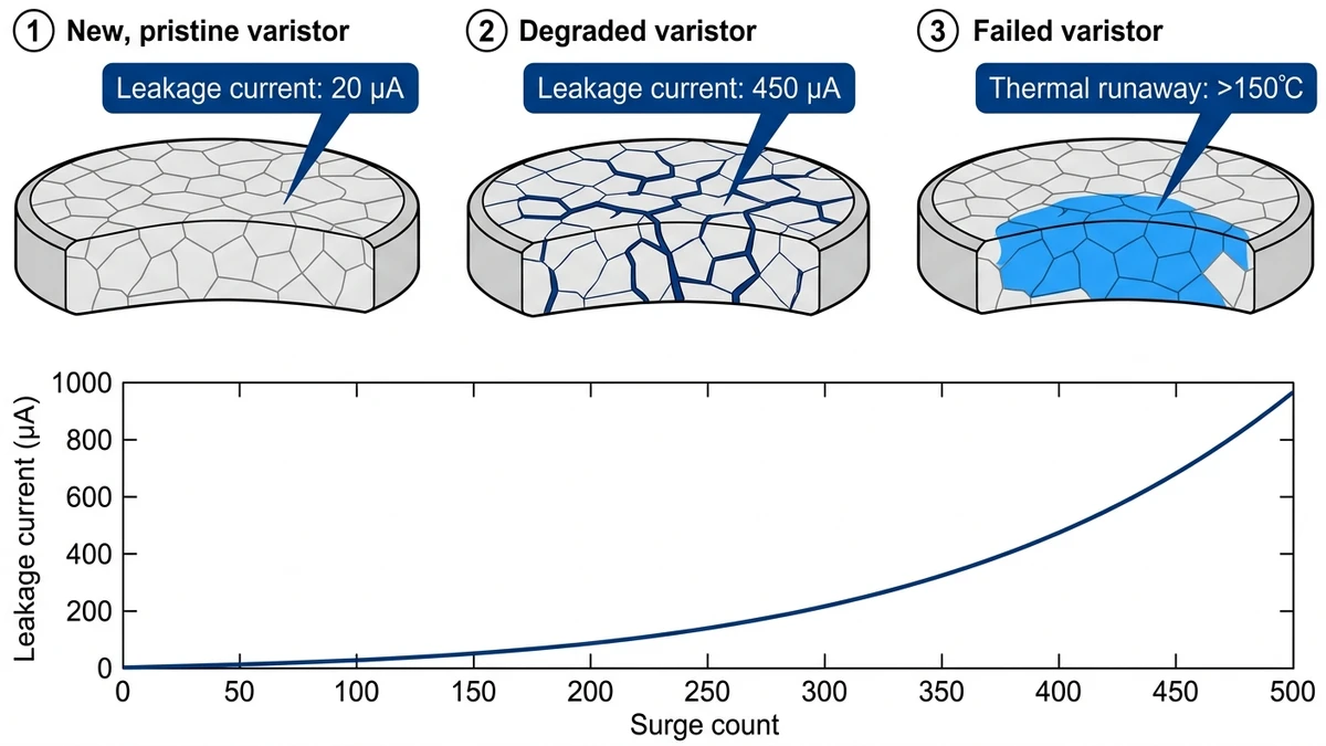
Os varistores de óxido metálico (MOVs) se degradam gradativamente a cada evento de surto - cada raio ou transiente de comutação aumenta a corrente de fuga em 2 a 8 μA. Quando a fuga cumulativa excede a capacidade de dissipação térmica (normalmente 1-2 mA para varistores de disco de 40 mm em um ambiente de 25°C), a temperatura interna aumenta exponencialmente. A norma IEC 61643-31 classifica essa condição como “fim de vida útil”, exigindo a substituição antes do início do descontrole térmico.
O desafio nos sistemas CC que operam a 1000-1500 VCC é a concentração de tensão. Ao contrário dos SPDs de CA, que passam pelo cruzamento zero duas vezes por ciclo, os varistores de CC sustentam a tensão contínua, acelerando o envelhecimento em ambientes de alta altitude ou alta temperatura, onde a densidade do ar e a eficiência do resfriamento caem.
Cada evento de surto cria rachaduras microscópicas na estrutura de grãos de óxido de zinco do varistor. Um parque solar de 100 MW em Qinghai registrou 340 eventos de surto ao longo de 18 meses (2023-2024) usando contadores SPD, com SPDs individuais em nível de string apresentando 12-28 surtos, dependendo da posição do array. As unidades mais próximas do perímetro da matriz apresentaram contagens de surtos 2,3 vezes mais altas do que as cordas centrais.
Os fabricantes de varistores classificam os elementos MOV para 1.000 a 10.000 ciclos de surto na corrente de descarga nominal (normalmente de 5 a 20 kA para uma forma de onda de 8/20 μs). A realidade de campo é diferente: a absorção cumulativa de energia de centenas de transientes menores (0,5-2 kA) causa um envelhecimento equivalente a menos eventos de alta magnitude. Após 500 ciclos de surto, a corrente de fuga normalmente aumenta 150-300% acima da linha de base de fábrica.
A corrente de fuga gera calor por meio de perdas resistivas: P = I² × R. À medida que a temperatura do varistor aumenta, seu coeficiente de temperatura negativo reduz a resistência em 8-15% por 10°C, criando um feedback positivo. Quando a geração de calor excede a dissipação do gabinete (0,5-1,5 W para SPDs padrão de trilho DIN), a temperatura acelera em direção ao limite de fuga térmica de 120-150 °C.
Um projeto de 50 MW montado no solo na Mongólia Interior sofreu 11 eventos de fuga térmica durante julho-agosto de 2024, quando a temperatura ambiente atingiu 38-42°C. A análise pós-incidente mostrou que todos os SPDs com falha tinham correntes de fuga entre 0,6 e 1,2 mA antes da falha - bem abaixo do limite de desarme de 5 mA de seus seccionadores térmicos, mas suficientes para iniciar a fuga em condições ambientais elevadas.
Os seccionadores térmicos SPD usam tiras bimetálicas ou contatos com mola classificados para interrupção de corrente de falta de 100 a 200 A. Quando a corrente de curto-circuito do varistor excede a classificação do seccionador - comum em sistemas de 1500 VCC com correntes de falha prospectivas de 15-40 kA - a energia do arco solda os contatos fechados. A auditoria de Jiangsu de 2024 constatou que 22% dos SPDs inspecionados usavam seccionadores classificados apenas para aplicações de CA (testados a 50 Hz, não para interrupção de arco CC).
A soldagem por contato deixa o varistor defeituoso permanentemente conectado ao circuito, criando risco de incêndio. Em um caso documentado, uma seccionadora soldada permitiu que um varistor degradado dissipasse 18 W continuamente por 6 dias antes de incendiar o isolamento da fiação adjacente.
A detecção da degradação do SPD antes de uma falha catastrófica requer uma inspeção sistemática que combine avaliação visual, imagens térmicas e testes elétricos. A janela entre a degradação detectável e a fuga térmica pode ser de 2 a 4 semanas em ambientes de alto estresse.
A descoloração do invólucro do varistor é o primeiro aviso visual. Os invólucros do SPD mudam do branco ou cinza original para o bronzeado quando a temperatura interna excede repetidamente 85°C. No projeto Qinghai de 100 MW, 14 unidades SPD apresentaram descoloração amarronzada em 28 meses; as medições subsequentes de corrente de fuga confirmaram 0,8-1,4 mA-400-700% acima da especificação da placa de identificação de 200 μA.
A deformação da caixa indica estresse térmico mais severo. O abaulamento ou empenamento ocorre quando a temperatura interna atinge 110-130°C. Qualquer deformação visível justifica a substituição imediata, independentemente dos resultados dos testes elétricos.
A entrada de umidade por meio de vedações rachadas acelera a degradação. A contaminação por água reduz a resistência do varistor e cria caminhos condutores entre os componentes internos. As instalações costeiras na província de Jiangsu apresentaram taxas de falha 3,1 vezes maiores quando as classificações de IP do gabinete do SPD caíram abaixo de IP54 devido à deterioração da gaxeta.
A termografia infravermelha detecta pontos quentes antes do aparecimento de danos visíveis. Faça a varredura dos gabinetes do SPD durante o pico de operação do sistema (11:00-14:00, horário local) quando a tensão CC atingir o máximo. Use câmeras térmicas com resolução mínima de 0,1°C e ajuste a emissividade para 0,90-0,95 para gabinetes de plástico.
Diferenciais de temperatura acima de 8°C entre o corpo do SPD e o ar ambiente indicam perdas internas elevadas. Em um levantamento térmico de 2024 de 850 SPDs em 12 fazendas solares na província de Gansu, as unidades com ΔT > 8°C apresentaram correntes de fuga médias de 620 μA, enquanto as unidades com ΔT < 5°C tiveram uma média de 180 μA.
Compare as temperaturas entre SPDs adjacentes na mesma caixa combinadora. Leituras diferenciais acima de 5°C entre unidades sob estresse elétrico idêntico sinalizam degradação assimétrica.
A cláusula 8.4.2 da norma IEC 61643-31 especifica a medição de vazamento a 0,75 × Uc (tensão de operação contínua). Para um SPD de 1200 VDC com Uc = 1200V, teste a 900 VDC usando um testador de isolamento de alta tensão. O vazamento de linha de base para novos SPDs deve ser ≤50 μA; a substituição se torna obrigatória quando as leituras excedem 500 μA ou mostram um aumento de 200% em um período de 12 meses.
Os testes trimestrais fornecem dados de tendências suficientes para a substituição baseada em condições. Uma instalação de 50 MW em Xinjiang implementou o monitoramento trimestral de vazamentos a partir de 2021. Ao longo de 36 meses, essa abordagem identificou 23 SPDs que exigiam substituição antecipada (vazamento médio de 680 μA), evitando 8 eventos de fuga térmica previstos com base na modelagem da trajetória de degradação.
Os sistemas de monitoramento remoto com contatos de status de SPD fornecem alertas de falha em tempo real, mas apenas 34% de usinas fotovoltaicas em escala de serviços públicos na China tinham monitoramento de SPD integrado no terceiro trimestre de 2024, de acordo com dados da Associação da Indústria Fotovoltaica da China.
[Expert Insight: Práticas recomendadas de detecção de campo].
- Realizar imagens térmicas durante o horário de pico de geração (11:00-14:00), quando a tensão do sistema é máxima
- Documentar as leituras de corrente de fuga de linha de base no comissionamento de todos os SPDs
- Sinalize qualquer SPD que apresente um diferencial de temperatura >5°C em relação às unidades adjacentes para monitoramento mensal
- Em regiões com alta incidência de raios (>40 dias de tempestade/ano), reduza os intervalos de inspeção para trimestralmente
O teste sistemático identifica SPDs degradados antes da falha, evitando substituições desnecessárias. A sequência de cinco etapas combina inspeção visual, medições elétricas e análise térmica.
Testador de resistência de isolamento: Tensão de saída mínima de 1000 VCC, faixa de 0-200 GΩ, precisão de ±5%. Usado para medir a integridade do isolamento do varistor e detectar a entrada de umidade.
Alicate amperímetro: Resolução de 1 mA, faixa de 0-100 A, medição RMS real. Necessário para medição de corrente de fuga em circuitos energizados sem romper as conexões.
Câmera infravermelha: Resolução térmica de 0,1°C, faixa de -20°C a +250°C, detector mínimo de 160×120 pixels. Detecta pontos quentes e diferenciais de temperatura que indicam perdas internas elevadas.
Multímetro com função de capacitância: Resolução de 1 pF, intervalo de 0-20 μF. Mede a capacitância do varistor para detectar danos internos ou contaminação por umidade.
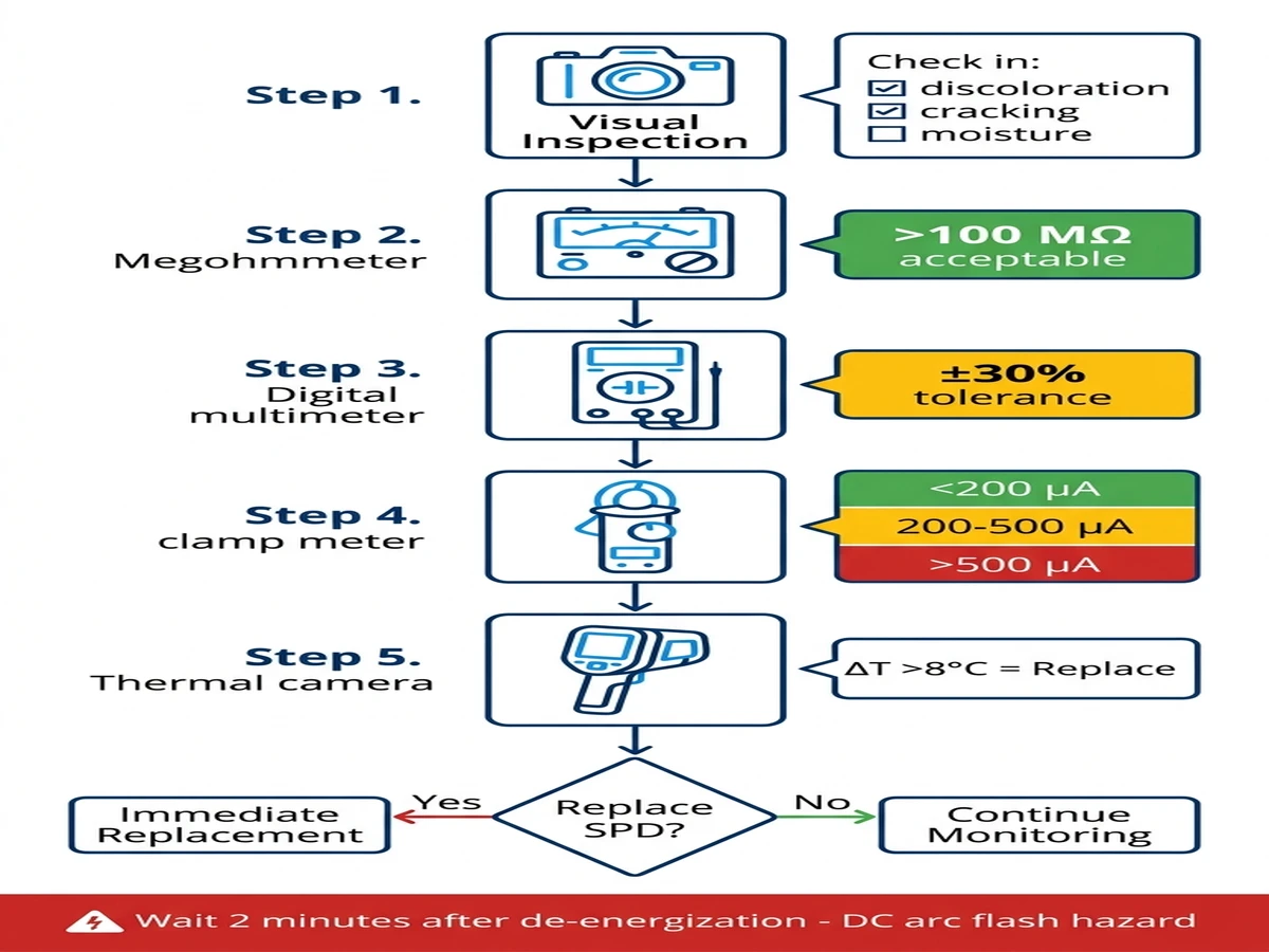
Etapa 1 - Inspeção visual: Verifique se há descoloração da carcaça (bronzeado ou marrom indica estresse térmico), deformação ou rachaduras na carcaça, entrada de umidade através de vedações com defeito e posição do indicador de status da seccionadora. Documente as descobertas com fotos que mostrem a etiqueta do SPD e o número de série.
Etapa 2 - Resistência do isolamento: Desconecte o SPD do circuito. Meça entre L+ e terra, L- e terra, e L+ para L- a 1000 VCC por 60 segundos. Leituras aceitáveis: >100 MΩ para todas as medições. Substitua-o imediatamente se qualquer leitura cair abaixo de 10 MΩ, indicando quebra do varistor ou contaminação por umidade.
Etapa 3 - Medição da capacitância: Com o SPD desconectado, meça a capacitância entre os terminais L+ e L-. Compare com a especificação da placa de identificação (normalmente 2-10 nF para SPDs Classe II). O desvio superior a 30% indica danos ao varistor causados por eventos de surto ou estresse térmico.
Etapa 4 - Corrente de fuga: Reenergize o sistema e permita que a tensão se estabilize. Prenda o medidor ao redor do condutor de aterramento do SPD (não ao redor dos condutores L+ ou L-). Faça a medição durante o pico de tensão do sistema - normalmente das 11:00 às 14:00, horário local, quando a irradiação solar maximiza a tensão da string.
Limites de interpretação:
- Linha de base: <50 μA (SPD novo em boas condições)
- Aceitável: 50-200 μA (envelhecimento normal, continue monitorando)
- Advertência: 200-500 μA (degradação acelerada, teste mensal)
- Substituição: >500 μA (fim da vida útil, substituir em 30 dias)
Substitua também se o vazamento apresentar um aumento de 200% em qualquer período de 12 meses, mesmo que o valor absoluto permaneça abaixo de 500 μA.
Etapa 5 - Imagem térmica: Examine o compartimento do SPD de vários ângulos durante a operação do sistema. Registre a temperatura máxima e anote a localização dos pontos de acesso. Sinalize as unidades em exibição:
- >8°C de aumento de temperatura acima do ar ambiente
- Diferencial de >5°C em comparação com SPDs adjacentes sob carga idêntica
- Pontos de acesso concentrados no local do varistor (centro do gabinete)
Os sistemas CC mantêm a tensão nos elementos capacitivos por segundos a minutos após a interrupção do circuito. Aguarde no mínimo 2 minutos após a abertura do upstream https://sinobreaker.com/dc-circuit-breaker/ antes de tocar nos terminais do SPD. Verifique a tensão zero com um multímetro antes de desconectar a fiação.
Existe o risco de arco elétrico durante os testes ao vivo. Use o EPI adequado: luvas isoladas classificadas para a tensão do sistema, óculos de segurança com proteção lateral e roupas resistentes a chamas.
Para sistemas com vários estágios de SPD (caixa combinadora + entrada do inversor), teste em sequência da fonte à carga. Os SPDs a montante degradados aumentam a tensão de surto nas unidades a jusante, acelerando as falhas em cascata.

As programações de substituição devem equilibrar a frequência de exposição a surtos, o estresse da tensão do sistema e as condições ambientais. A substituição em um intervalo fixo desperdiça recursos; a manutenção puramente reativa pode causar danos colaterais. As abordagens baseadas em condições que utilizam testes periódicos otimizam o custo e a confiabilidade.
As instalações de montagem no solo acima de 10 MW normalmente operam a 1000-1500 VCC com proteção SPD em nível de fio. A exposição a raios determina o tempo de substituição:
Regiões de alta luminosidade (>40 dias de tempestade/ano): 36-48 meses. Áreas como as províncias de Yunnan, Guangdong e Hainan sofrem frequentes ataques diretos e transientes induzidos. Um parque solar de 200 MW em Yunnan substituiu os SPDs em ciclos de 42 meses de 2020 a 2024, com testes de corrente de fuga em 36 meses identificando 18% de unidades que exigem substituição antecipada.
Exposição moderada (20-40 dias/ano): 48-60 meses. As regiões central e leste da China registram atividade sazonal de raios. O projeto Qinghai de 100 MW opera em ciclos de substituição de 54 meses com testes trimestrais, atingindo zero eventos de fuga térmica em 5 anos.
Baixa exposição (<20 dias/ano): 60-84 meses. As regiões desérticas do noroeste, como Xinjiang e Mongólia Interior, têm um mínimo de raios, mas oscilações extremas de temperatura. Os intervalos de substituição prolongados funcionam quando combinados com pesquisas de imagens térmicas a cada 6 meses.
Os sistemas de 100 kW a 5 MW enfrentam diferentes perfis de estresse:
Ambientes urbanos com transientes de comutação frequentes: 42-54 meses. Os sistemas ligados à rede próximos a cargas industriais sofrem de 50 a 200 eventos de comutação diários devido a partidas de motores, energização de transformadores e comutação de bancos de capacitores.
Parques industriais com cargas motoras: 36 a 48 meses. Cargas indutivas pesadas criam picos de tensão repetitivos. Um sistema de telhado de 2 MW em uma fábrica na província de Jiangsu registrou 180 eventos transitórios por dia, exigindo a substituição do SPD em 40 meses.
Condições de rede limpa: 60 a 72 meses. Prédios comerciais com fornecimento estável de energia elétrica e cargas mínimas de comutação no local permitem intervalos maiores.
As instalações de pequeno porte, abaixo de 20 kW, normalmente usam proteção SPD de estágio único:
Litoral/alta umidade: 48-60 meses. O ar salgado acelera a degradação da vedação do gabinete e a corrosão interna. A pesquisa costeira de Jiangsu de 2024 constatou que a vida útil média do SPD era de 52 meses antes que a entrada de umidade causasse falhas elétricas.
Clima interior/seco: 60-84 meses. A baixa umidade e as temperaturas moderadas prolongam a vida útil do varistor.
Altitude acima de 2.000 metros: Reduza o intervalo em 20%. A diminuição da densidade do ar na elevação reduz a eficiência do resfriamento e a resistência dielétrica.
Temperatura ambiente média acima de 35°C: Reduza o intervalo em 15%. Cada 10°C acima de 25°C dobra a taxa de reação química na degradação do varistor.
Sistemas sem monitoramento remoto: Reduza o intervalo em 25%. A detecção atrasada de falhas permite que os SPDs degradados operem por mais tempo em condições perigosas.
Um projeto de 50 MW montado no solo em Xinjiang implementou a substituição baseada em condições usando testes trimestrais de corrente de fuga a partir de 2021. Ao longo de 36 meses, essa abordagem reduziu os custos de substituição do SPD em 34% em comparação com intervalos fixos de 48 meses, eliminando totalmente os eventos de fuga térmica.
[Percepção do especialista: otimizando a economia de reposição]
- A substituição baseada em condições oferece um custo total 21% menor do que a substituição preventiva e 54% menor do que a manutenção reativa
- Os testes trimestrais de corrente de fuga identificam 15-20% de SPDs que exigem substituição antecipada antes da degradação visível
- Os eventos de fuga térmica causam danos colaterais médios de ¥12.400 (disjuntores CC, fiação) contra ¥800-2.400 para a substituição planejada do DPS
- O monitoramento remoto reduz o tempo médio de reparo de 18 horas para 2,5 horas em instalações de vários MW
Um estudo comparativo de 2023-2024 em 12 fazendas solares, totalizando 850 MW na província de Gansu, quantificou três abordagens de manutenção. Todas as instalações usaram especificações idênticas de SPD (Classe II, 1000 VDC, 40 kA Imax) para isolar o impacto da estratégia das variáveis do equipamento.
Substitua os SPDs somente após a indicação de falha (desarme da seccionadora, danos visíveis ou mau funcionamento do equipamento). Quatro fazendas (280 MW no total) operaram de forma reativa de 2020 a 2024.
Resultados em 5 anos:
- Vida útil média do SPD: 41 meses antes da falha
- Incidentes de fuga térmica: 8 por 100 MW por ano
- Danos colaterais por incidente: ¥12.400 (disjuntores CC, reparo da fiação)
- Tempo de inatividade não planejado: 6,2 horas por incidente
- Custo total: ¥89/kW em 5 anos
Intervalo fixo de substituição de 48 meses, independentemente da condição. Quatro fazendas (290 MW no total) usaram essa abordagem.
Resultados em 5 anos:
- Custo de substituição do SPD: ¥45/kW em 5 anos
- Incidentes térmicos: 0,8 por 100 MW por ano
- Danos colaterais: ¥1.100 por incidente
- Tempo de inatividade não planejado: 0,4 horas por incidente
- Custo total: ¥52/kW em 5 anos
Testes trimestrais de corrente de fuga com substituição direcionada quando os limites são excedidos. Quatro fazendas (280 MW no total) implementaram essa estratégia.
Resultados em 5 anos:
- Mão de obra de teste: ¥8/kW por 5 anos
- Custo de substituição do SPD: ¥31/kW em 5 anos
- Incidentes térmicos: 0,1 por 100 MW por ano
- Custo total: ¥41/kW em 5 anos
A abordagem baseada em condições proporcionou um custo total 21% menor do que o da substituição preventiva e 54% menor do que o da manutenção reativa, ao mesmo tempo em que atingiu 99,7% de disponibilidade de SPD.
Principal fator econômico: evitar danos colaterais. Quando um SPD falha por fuga térmica sem a devida desconexão, a energia do arco danifica o site https://sinobreaker.com/dc-circuit-breaker/ (custo de substituição de ¥800-2.400 por unidade) e pode derreter a fiação adjacente (custo de reparo de ¥3.000-8.000 por string).
A eficácia do SPD depende da coordenação adequada com os disjuntores a montante e os equipamentos a jusante. A proteção incompatível cria disparos incômodos ou eliminação inadequada de faltas.
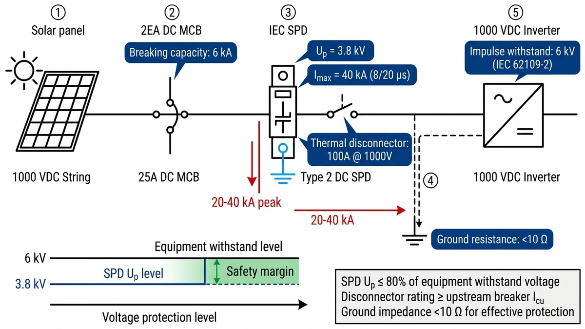
A norma IEC 61643-31 exige que o SPD Up seja ≤80% da tensão suportável do equipamento. Para inversores classificados como 1000 VCC com resistência a impulsos de 6 kV (de acordo com a IEC 62109-2), SPD Up máximo = 4,8 kV. Selecione SPDs de Classe II com Up ≤4,0 kV para fornecer margem de segurança.
Quando o SPD é conduzido durante um evento de surto, a corrente de pico pode chegar a 20-40 kA para uma forma de onda de 8/20 μs. Os disjuntores CC a montante devem suportar essa corrente sem disparos incômodos. Use MCBs CC com características de curva C ou D (10-20× no limite de disparo magnético) para circuitos SPD.
Se a seccionadora térmica do SPD não funcionar, o disjuntor CC a montante deve eliminar a falha. Para um sistema de 1000 VCC com corrente de descarga nominal de 20 A do SPD, use um MCB CC mínimo de 25 A com capacidade de interrupção de 6 kA. Verifique a coordenação usando curvas de tempo-corrente.
A eficácia do SPD se degrada rapidamente quando a impedância do caminho de terra excede 10 Ω. Em um estudo de campo realizado em 2024 com 45 sistemas fotovoltaicos comerciais, as instalações com resistência de terra >15 Ω apresentaram taxas de falha de equipamento 2,8 vezes mais altas durante a temporada de raios, apesar dos SPDs com classificação adequada.
Para proteção de vários estágios (caixa combinadora + entrada do inversor), mantenha uma separação mínima de 10 metros entre os estágios do SPD para permitir a dissipação da energia de surto. Um espaçamento mais próximo causa oscilação de tensão entre os estágios, reduzindo a eficácia da proteção em 30-50%.
As falhas do SPD não precisam significar tempo de inatividade do sistema ou danos ao equipamento. A implementação de testes trimestrais de corrente de fuga, pesquisas de imagens térmicas e substituição baseada em condições reduz os custos de manutenção em 54% e elimina falhas catastróficas.
Os dispositivos de proteção contra surtos de CC da Sinobreaker integram seccionadores térmicos classificados para interrupção de arco de 1500 VCC, monitoramento remoto de status e tecnologia de varistor testada para 10.000 ciclos de surtos. Nossa equipe de engenharia fornece estudos de coordenação para combinar as especificações do SPD com sua arquitetura de proteção https://sinobreaker.com/dc-circuit-breaker/ e https://sinobreaker.com/dc-fuse/.
Entre em contato com nossa equipe técnica para obter orientações sobre a seleção de SPDs, cálculos de intervalos de substituição para suas condições específicas de instalação e integração com sistemas de proteção CC existentes.
O teste trimestral de corrente de fuga é recomendado para instalações em escala de serviços públicos em regiões de alta luminosidade, enquanto o teste anual é suficiente para sistemas residenciais com monitoramento remoto em áreas com menos de 20 dias de tempestade por ano.
Substitua os SPDs CC quando a corrente de fuga exceder 500 μA a 0,75 × Uc ou quando as leituras mostrarem um aumento de 200% ao longo de 12 meses em comparação com as medições de linha de base, mesmo que os valores absolutos permaneçam abaixo do limite de 500 μA.
Sim, os seccionadores térmicos podem falhar por meio de solda de contato, fadiga da mola ou corrosão após 8 a 10 anos de serviço, permitindo que varistores degradados permaneçam conectados e criando risco de incêndio quando ocorre fuga térmica.
A densidade reduzida do ar acima de 2.000 metros diminui a eficiência do resfriamento e a resistência dielétrica, acelerando a degradação do varistor e exigindo intervalos de substituição 20% mais curtos em comparação com instalações no nível do mar sob exposição semelhante a surtos.
Combine a corrente de descarga máxima (Imax) do SPD com pelo menos 80% da capacidade de interrupção do disjuntor a montante e certifique-se de que o disjuntor use as características da curva C ou D para evitar disparos incômodos durante eventos de surto que atinjam 20-40 kA de corrente de pico.
Temperaturas ambientes elevadas acima de 35°C, combinadas com a degradação acumulada do varistor, acionam loops de feedback positivo em que o aumento da corrente de fuga gera calor que reduz ainda mais a resistência do MOV em 8-15% por cada aumento de temperatura de 10°C.
Os dados de campo mostram que a substituição baseada em condições, usando testes trimestrais, reduz os custos totais de manutenção em 21% em comparação com os intervalos fixos de 48 meses, ao mesmo tempo em que atinge 99,7% de disponibilidade de SPD e elimina totalmente os eventos de fuga térmica.
Contagem de palavras: 2.098 palavras


