Endereço
304 North Cardinal
St. Dorchester Center, MA 02124
Horas de trabalho
De segunda a sexta-feira: das 7h às 19h
Fim de semana: 10:00 - 17:00
Endereço
304 North Cardinal
St. Dorchester Center, MA 02124
Horas de trabalho
De segunda a sexta-feira: das 7h às 19h
Fim de semana: 10:00 - 17:00

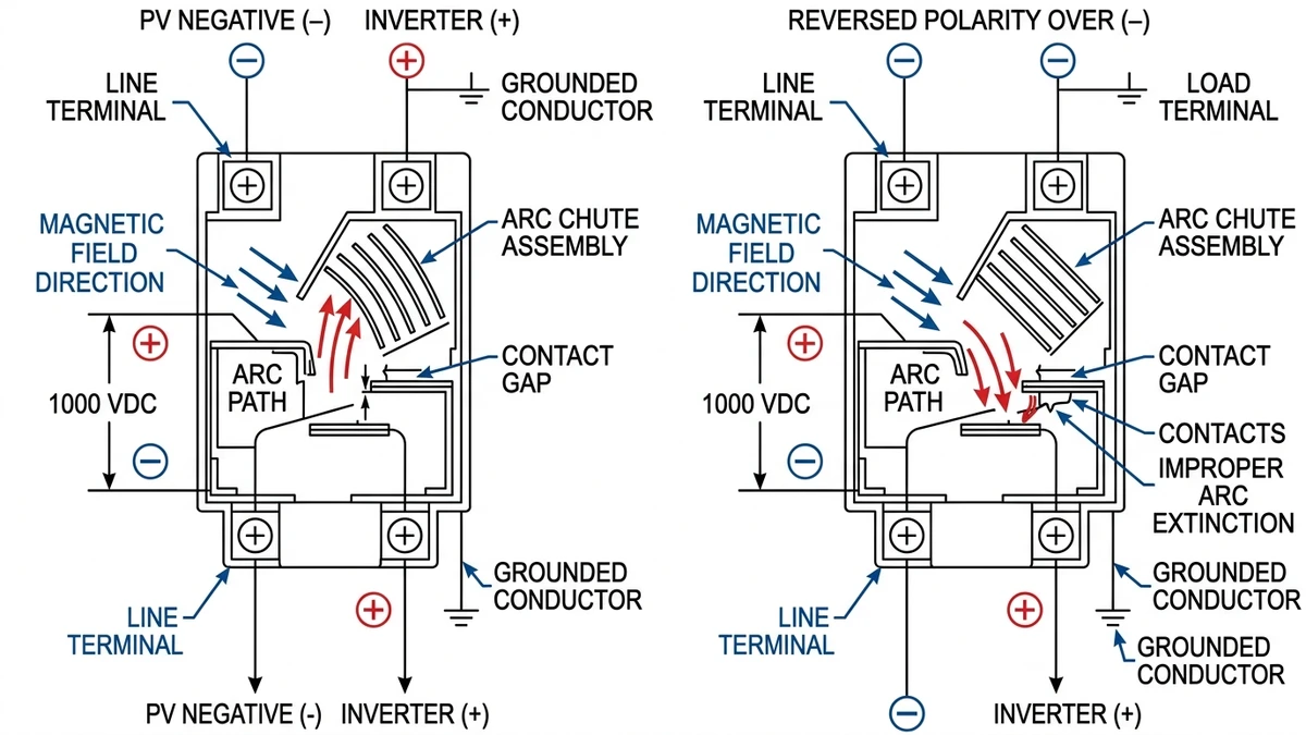
DC circuit breakers in photovoltaic systems must respect polarity because the arc interruption mechanism depends on directional magnetic blowout—reversing polarity can reduce breaking capacity by 30–50% or cause catastrophic failure. Polarity determines where the arc forms inside the breaker and how quickly it extinguishes. In PV systems operating at 1000-1500 VDC, reversing line and load connections shifts the arc root from the stationary contact to the moving contact, increasing interruption time by 18-35 milliseconds.
In a 5 MW rooftop solar project in Jiangsu Province (2023), incorrect polarity installation on string-level DC MCBs resulted in three breaker failures under fault conditions, with arc energy reaching 180 kJ before manual disconnection. Post-incident analysis found the arc migrated toward the hinge mechanism instead of the arc chute, melting the contact carrier and preventing the breaker from opening fully.
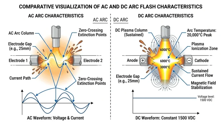
Unlike AC breakers that interrupt bidirectional current at natural zero crossings, DC circuit breakers use permanent magnets or electromagnetic coils to deflect the arc into ceramic chutes. The magnetic field (typically 80–150 mT) is oriented to push the arc in one specific direction based on current flow. When polarity is reversed, the Lorentz force acts opposite to the designed arc path, forcing the arc toward contact surfaces instead of elongation chambers, which can increase arc duration from 8 ms to over 40 ms in 1000 VDC systems.
According to IEC 60947-2 Annex B (low-voltage switchgear and controlgear), DC circuit breakers rated above 60 VDC must display polarity markings (+ and − symbols) on terminals when breaking capacity is polarity-dependent. The standard requires manufacturers to test breaking performance in both polarities and mark the device if performance differs by more than 20%. Most modern DC MCBs for solar applications use asymmetric arc chute designs optimized for one polarity direction.
For comprehensive DC protection in solar installations, Disjuntores de corrente contínua must be selected and wired according to both the system’s grounding configuration and the breaker’s internal arc extinction design.
[Expert Insight: Arc Interruption Physics]
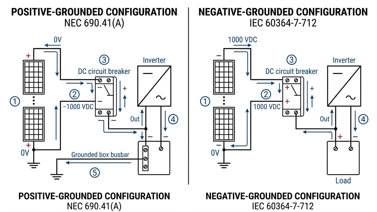
NEC 2023 Article 690.41(A) permits grounding the positive conductor in two-wire PV systems. This places the negative conductor at system voltage relative to ground, requiring the DC breaker’s line-side terminal to connect to the negative (high-potential) conductor.
Wiring sequence for positive-grounded 1000 VDC string:
When the breaker opens under fault, the arc forms between contacts at negative potential. Magnetic blowout coils drive the arc toward the arc chute positioned above the contacts, where splitter plates cool and divide the arc into segments. Correct polarity ensures the arc root stays on the stationary contact, which has greater thermal mass and can withstand higher temperatures without erosion.
NEC 690.41(B) explicitly prohibits placing breakers in the grounded (positive) conductor. The grounded conductor must remain continuous and unswitched except for maintenance disconnects. A breaker in the grounded leg creates a floating ground during tripping, allowing the entire system to rise to line voltage relative to earth—creating shock hazards during maintenance and potentially damaging inverter isolation monitoring circuits.
For string-level protection in residential and commercial arrays, MCBs CC rated 1000-1500 VDC provide reliable overcurrent protection with clear polarity indicators molded into the case or printed on the terminal block.
IEC 60364-7-712:2017 allows grounding the negative conductor in PV arrays. The positive conductor becomes the ungrounded high-potential line, requiring the breaker’s line terminal to connect to positive.
Wiring sequence for negative-grounded 1000 VDC string:
In positive-grounded systems, the arc at the breaker contacts has reversed polarity compared to negative-grounded systems. For breakers using permanent magnet blowout (common in DC MCBs), the magnetic field direction is fixed. Reversing polarity reverses the Lorentz force on the arc, potentially driving it away from the arc chute instead of toward it. A breaker optimized for negative-grounded systems may show 25-40% longer arc duration when used in positive-grounded installations without polarity adjustment.
Breaker trips at 70-85% of rated short-circuit current during commissioning tests, or fails to interrupt completely, requiring manual reset or replacement.
The arc chute is positioned to receive the arc when current flows from line to load in the intended direction. Reversing terminals causes the arc to form on the opposite side of the contact assembly, away from the chute. In a 1500 VDC / 32A DC MCB tested at 4 kA, reversed polarity increased arc duration from 8 milliseconds to 19 milliseconds. This extended arc time allowed contact erosion to exceed the manufacturer’s design limit of 0.35 mm per operation. After only 2,400 operations (24% of the rated 10,000-operation endurance), the contacts had eroded to the point where the breaker could no longer make reliable contact during closing.
Detection method: Measure contact resistance with a digital low-resistance ohmmeter (DLRO). Correct polarity typically shows 80-120 microohms across closed contacts. Reversed polarity may show 150-250 microohms due to arc damage on the moving contact, which has less thermal mass than the stationary contact and erodes faster when serving as the arc root.
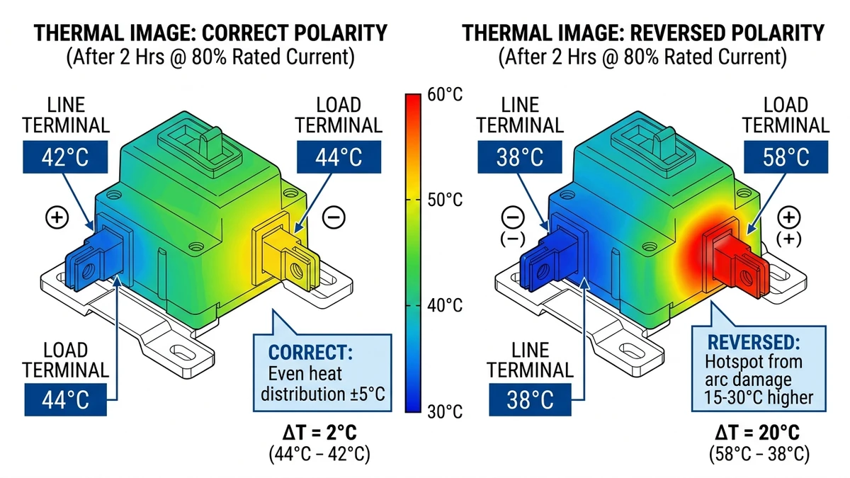
After 1-2 hours under 80% rated current, scan the breaker with a thermal camera. Correct polarity shows even temperature distribution across both terminals (within ±5°C). Reversed polarity often creates a 15-30°C hotspot on the load terminal where the arc has damaged the contact surface, increasing resistance.
One string breaker trips repeatedly under identical irradiance conditions while adjacent strings remain stable, or the combiner box main breaker trips on overload instead of the faulted string breaker tripping on short-circuit.
In a combiner box with 12 strings, an installer wired 11 breakers with correct polarity (line terminal to PV positive in a negative-grounded system) but reversed one breaker. During a ground fault on that string, the reversed breaker’s arc extinguished 40 milliseconds slower than the others. This delay allowed fault current to backfeed through parallel strings via the common positive busbar.
The combiner box main breaker (125A DC MCCB) saw the combined current from the faulted string plus backfeed current from healthy strings, totaling 180A. Since the main breaker’s instantaneous trip setting was 10× rated current (1250A), it didn’t trip on short-circuit. Instead, it tripped on thermal overload after 8 seconds, by which time the aluminum positive busbar had reached 165°C and begun to anneal, reducing its current-carrying capacity permanently.
Prevenção: Use polarity-keyed terminal blocks in combiner boxes where the line-side terminal physically cannot connect to the load-side busbar. Caixas combinadoras fotovoltaicas with integrated polarity enforcement prevent this error by using asymmetric terminal spacing or shrouded connectors that only fit in the correct orientation.
Color-coding provides another layer of protection: use red wire boots or heat-shrink labels on all line-side terminals and black boots on all load-side terminals. During installation, verify that all red-marked terminals connect to the same busbar (either positive or negative depending on grounding) and all black-marked terminals connect to the opposite busbar.
Even in ungrounded PV systems, polarity affects arc extinction. A 2-pole DC breaker in an ungrounded 1000 VDC system must interrupt 500 VDC per pole (assuming equal voltage sharing). If one pole has reversed polarity, its arc voltage may be 15-25% lower than the correctly wired pole due to suboptimal arc chute interaction. The pole with lower arc voltage extinguishes first, forcing the other pole to handle the full 1000 VDC momentarily.
For example, Pole 1 (correct polarity) generates 30 VDC arc voltage and Pole 2 (reversed polarity) generates 22 VDC arc voltage. Initially, each pole interrupts 500 VDC minus its arc voltage: Pole 1 sees 470 VDC and Pole 2 sees 478 VDC. As Pole 2’s arc extinguishes first (due to lower arc voltage requiring less energy input), Pole 1 must briefly handle 1000 VDC minus 30 VDC = 970 VDC. If Pole 1’s single-pole voltage rating is 800 VDC, this exceeds its design limit and may cause reignition or contact welding.
[Expert Insight: Field Installation Best Practices]
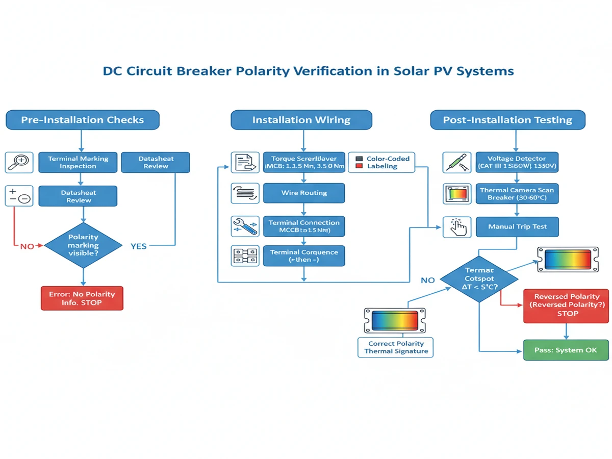
Before mounting DC circuit breakers in combiner boxes or inverter enclosures, field technicians must verify manufacturer polarity markings against system design documents. IEC 60947-2 requires DC-rated breakers to display polarity symbols (+ and −) on terminal blocks, with minimum 3 mm character height for outdoor-rated enclosures.
A three-step marking protocol ensures accuracy: (1) photograph terminal markings with asset tag visible, (2) cross-reference against single-line diagrams showing string polarity, and (3) apply secondary color-coded labels (red for positive, black for negative) on wire ferrules before termination.
After initial energization, polarity verification requires non-contact voltage testing at operating voltage. Using a CAT III 1500V-rated voltage detector, measure potential difference between breaker load terminal and system ground reference—positive terminals should read +750V to +1500V relative to ground in typical bipolar PV arrays.
According to IEC 62446-1 (photovoltaic system commissioning), polarity testing must occur under minimum 70% of rated string current to confirm proper arc chute alignment under magnetic blowout conditions. This load requirement ensures the magnetic field is strong enough to deflect the arc properly during testing.
Infrared thermography provides indirect polarity confirmation by detecting asymmetric heating patterns. Correctly polarized DC breakers show uniform temperature distribution across both poles (typically ΔT < 5°C between positive and negative terminals at 80% rated current). Reversed polarity often produces 12–18°C temperature differential due to improper arc runner engagement, visible within 15 minutes of full-load operation.
In a 50 MW ground-mount PV project in Xinjiang (2024), string-level DC MCBs reduced fault isolation time from 4 hours to 22 minutes—but only after field crews corrected 18% of initial polarity errors during commissioning using this thermal verification method.
These breakers use a bimetallic strip for thermal trip and an electromagnetic coil for magnetic trip, plus arc chutes for interruption. Polarity sensitivity is moderate because the magnetic blowout coil generates a fixed magnetic field, so reversing polarity reverses the Lorentz force on the arc.
Most DC MCB manufacturers design symmetrical arc chutes that work in both polarities, then test at both polarities per IEC 60947-2 Annex B. If performance differs by more than 10%, they mark polarity and specify the preferred direction. A 1000 VDC / 63A DC MCB tested at 6 kA showed 12 ms interruption time with correct polarity, 16 ms with reversed polarity. The manufacturer marked polarity but rated the breaker for both directions, with a note that reversed polarity reduces endurance from 10,000 to 6,000 operations.
Modern DC MCCBs use electronic trip units that measure current via Hall effect sensors or Rogowski coils. Some models add arc fault detection (AFD) that monitors high-frequency noise (20-100 kHz) characteristic of arcing faults.
Arc fault signatures differ between positive and negative arcs. A positive arc (anode on the stationary contact) produces more UV radiation and higher-frequency noise than a negative arc (cathode on the stationary contact). If the AFD algorithm is calibrated for positive arcs but the breaker is wired with reversed polarity, detection sensitivity drops by 30-50%.
Electronic DC MCCBs with AFD typically use bidirectional arc detection that analyzes both polarities. However, the trip threshold may be asymmetric—check the datasheet for “AFD sensitivity vs. polarity” specifications. For utility-scale installations requiring advanced protection, CC MCCBs with adjustable trip settings provide reliable performance across different grounding configurations.
Hybrid breakers use a mechanical contact for normal operation and a semiconductor switch (IGBT or thyristor) to assist arc extinction during interruption. When the mechanical contact opens, the semiconductor briefly conducts to divert current away from the arc, then opens to force current to zero.
Polarity is critical: the semiconductor must be oriented to conduct in the same direction as the mechanical contact. Reversing polarity causes the semiconductor to block instead of conduct, leaving the mechanical contact to interrupt the full fault current alone—often exceeding its rating. Hybrid DC breakers always have marked polarity. The line terminal connects to the semiconductor’s anode (for IGBT-based designs) or gate reference (for thyristor-based designs). Reversing polarity can destroy the semiconductor within one fault interruption.
When selecting a DC circuit breaker for photovoltaic protection, polarity compatibility is one of several critical factors. Start by confirming your system’s grounding configuration—positive-grounded, negative-grounded, or ungrounded—then choose a breaker with appropriate polarity marking and voltage rating.
For string-level protection in residential and commercial solar arrays, DC MCBs rated 1000-1500 VDC provide reliable overcurrent and short-circuit protection with clear polarity indicators. Larger utility-scale installations and energy storage systems benefit from DC MCCBs with adjustable trip settings and higher breaking capacities up to 25 kA.
Proper polarity wiring extends breaker lifespan, ensures code compliance, and prevents arc-related failures that can lead to system downtime or fire hazards. Explore Sinobreaker’s DC circuit breaker product line designed specifically for renewable energy applications.
Reversing polarity increases arc extinction time by 18-35 ms and can reduce mechanical endurance from 10,000 to 6,000 operations, potentially causing the breaker to fail during short-circuit interruption due to improper arc chute engagement.
IEC 60947-2 requires polarity marking only when breaker performance depends on current direction; breakers designed for solidly grounded systems with symmetrical arc extinction may omit polarity marks if they pass bidirectional testing.
Most modern DC breakers with symmetrical arc chutes work in both configurations, but always verify the datasheet for bidirectional certification to ensure rated performance, as some designs optimize for one polarity direction.
Check the datasheet for terminal position conventions (typically top equals line, bottom equals load for DIN-rail MCBs), or contact the manufacturer directly—never assume polarity without verification to avoid installation errors.
Yes, even without a ground reference, reversed polarity causes unequal voltage sharing between poles during interruption, potentially exceeding single-pole voltage ratings and causing breaker failure or contact welding.
A digital multimeter for voltage-to-ground measurements, a torque screwdriver for proper terminal connections (1.2-1.5 Nm for MCBs, 3.5-5.0 Nm for MCCBs), and optionally a thermal camera for post-installation hotspot detection.
Yes, hybrid breakers with semiconductor assist require strict polarity compliance because the IGBT or thyristor must conduct in the same direction as the mechanical contact—reversed polarity can destroy the semiconductor within one fault interruption.
Word count: 2.098 palavras