Endereço
304 North Cardinal
St. Dorchester Center, MA 02124
Horas de trabalho
De segunda a sexta-feira: das 7h às 19h
Fim de semana: 10:00 - 17:00
Endereço
304 North Cardinal
St. Dorchester Center, MA 02124
Horas de trabalho
De segunda a sexta-feira: das 7h às 19h
Fim de semana: 10:00 - 17:00


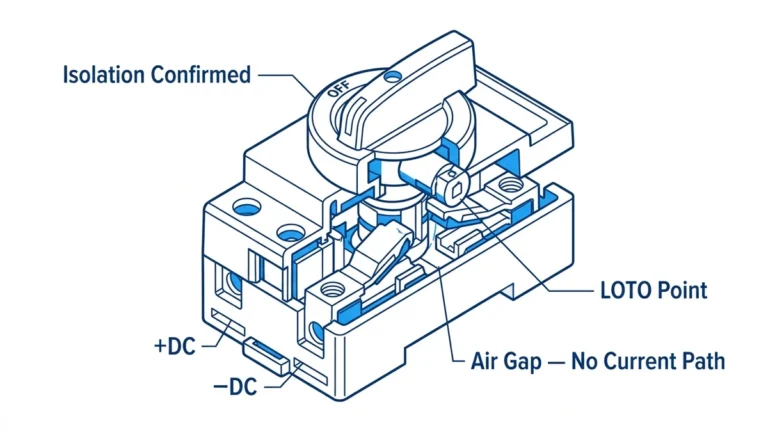
A dc disconnector switch is a manually operated isolation device that creates a physical air gap in DC circuits, with specifications determining whether it can safely interrupt current under load or requires de-energization before operation. Understanding the critical difference between load break and non-load break specifications prevents catastrophic arc flash incidents, equipment damage, and ensures code-compliant system design for solar PV, battery storage, and industrial DC power applications.
This specification-focused guide helps system designers, procurement engineers, and electrical contractors select the right DC disconnector by analyzing load break capabilities, voltage/current ratings, environmental enclosure requirements, and certification standards. We decode IEC 60947-3 utilization categories (DC-20, DC-21, DC-22, DC-23), compare NEMA 1-4X enclosure specifications, and provide decision matrices that match
disconnect specifications to application requirements.
For engineers specifying 600V-1500V DC systems with currents ranging from 30A to 1200A, incorrect disconnector specification creates either over-engineered costly solutions or dangerous under-specified switches that fail during emergency operations. This guide ensures specification precision.
⚠️ Aviso de especificação crítica: A non-load break disconnector specified in a position requiring load interruption creates severe arc flash hazard. Always verify utilization category (AC-21 vs AC-23 equivalent for DC) matches operational requirements before specifying equipment.
Electrical Specifications:
Tensão operacional nominal (Ue): Maximum DC system voltage
– Common ratings: 600V DC, 1000V DC, 1500V DC
– Must exceed maximum system voltage including transients
– Standards: IEC 60947-3, UL 98
Rated Operational Current (Ie): Continuous current capacity
– Range: 30A – 1200A for solar applications
– Temperature derating required above 40°C ambient
– Must consider conductor ampacity per NEC 310.15
Making Capacity (Icm): Maximum current switch can close onto
– Typically 10-15x rated current for inrush
– Critical for capacitor bank or transformer energization
Breaking Capacity (Icw): Short-time withstand current
– 1-second rating: typically 10-25x Ie
– Protects during upstream breaker clearing time
Mechanical Specifications:
Vida mecânica: Number of no-load operations
– Non-load break: 10,000-50,000 operations
– Load break: 5,000-25,000 operations (reduced due to arc erosion)
Contact Gap: Visible isolation distance when open
– Minimum: 3mm for 600V, 6mm for 1000V, 12mm for 1500V
– Ensures dielectric strength and visual verification
Operating Force: Manual handle effort
– Typical: 50-150N (11-34 lbf) for 100A-400A switches
– Must comply with ergonomic standards for accessibility
Environmental Specifications:
Enclosure Rating: Protection against ingress
– NEMA 1 (indoor, basic)
– NEMA 3R (outdoor, rain-proof)
– NEMA 4/4X (outdoor, hose-proof, corrosion-resistant)
– IP equivalents: IP65, IP66, IP67
Faixa de temperatura: Operating and storage limits
– Standard: -25°C to +70°C
– Extended: -40°C to +85°C for harsh environments
Derivação de altitude: Voltage reduction above 2000m
– 10% per 1000m above 2000m (thinner air, lower dielectric strength)
IEC 60947-3: Low-voltage switchgear and controlgear – Switches, disconnectors, switch-disconnectors and fuse-combination units
– Utilization categories DC-20 through DC-23
– Type testing requirements for electrical life
UL 98: Enclosed and Dead-Front Switches
– North American safety certification
– Arc flash hazard mitigation requirements
IEEE 1547/UL 1741: Solar PV interconnection standards
– Visible break requirement for PV disconnects
– Rapid shutdown integration (NEC 690.12)
CSA C22.2 No. 4: Enclosed switches and motor circuit switches
– Canadian market requirements

Definition: Switch capable of making and breaking current under normal operating conditions (not fault current)
Load Break Capability Requirements:
Interrupção de arco: Mechanism to extinguish DC arc
– Magnetic blow-out coils deflect arc into arc chutes
– De-ion grids break arc into smaller segments
– Arc chamber volume provides plasma cooling
Material de contato: Silver-tungsten or copper-tungsten alloy
– High melting point (3422°C tungsten vs 1085°C copper)
– Resists erosion from repetitive arcing
– Typical life: 3,000-10,000 load break operations
Utilization Categories (IEC 60947-3 DC equivalents):
| Categoria | Tipo de carga | Making Capacity | Capacidade de ruptura | Aplicação típica |
|---|---|---|---|---|
| DC-20A | Resistivo | 1.1 × Ie | 1.0 × Ie | Heating elements, resistor banks |
| DC-21A | Indutivo | 2.5 × Ie | 2.5 × Ie | DC motors, solenoids (5τ time constant) |
| DC-22A | Inductive Heavy | 6 × Ie | 6 × Ie | DC motors (15τ time constant) |
| DC-23A | Capacitivo | 15 × Ie | 1.0 × Ie | Capacitor banks, inverter input stages |
Load Break Applications:
– Main service disconnect (can isolate under load for maintenance)
– Emergency shutdown switches (must interrupt running system)
– Source transfer switches (switch between PV and grid)
– Motor control (start/stop DC motors)
Prêmio de custo: 2-4x non-load break equivalent
Definition: Switch designed ONLY for isolation when circuit is de-energized
Non-Load Break Specifications:
No Arc Interruption Capability: Simple air-break contacts
– Minimal contact gap (3-6mm)
– No arc chutes or blow-out coils
– Standard copper or brass contacts
Operation Sequence Required:
1. Open upstream circuit breaker (breaks load current)
2. Verify zero current with ammeter
3. Open disconnector (creates isolation gap)
4. Lock out and tag out for safety
Contact Life: 10,000-50,000 mechanical operations
– No arc erosion extends mechanical life
- Menores requisitos de manutenção
Non-Load Break Applications:
– Maintenance isolation (downstream of load-breaking device)
– Visible verification of de-energization
– Lockout/tagout safety positions
– Test point isolation
Cost Advantage: 25-50% of load break switch cost
DANGER – Arc Flash Hazard: Installing non-load break disconnector in position requiring load interruption
Cenário: Maintenance technician opens non-load break isolator under 200A load at 600V DC:
– Arc voltage: 50-100V
– Arc power: 10-20kW
– Plasma temperature: 6,000-10,000K (hotter than sun’s surface)
- Resultado: Explosive arc flash, severe burns, equipment destruction
Prevenção:
– Specify load break switch for any position that might be operated under load
– Label non-load break isolators: “WARNING – OPEN ONLY UNDER NO LOAD”
– Provide operational ammeter to verify zero current before opening
| Especificação | Load Break Switch | Non-Load Break Isolator |
|---|---|---|
| Can Break Load Current | ✅ Yes (rated) | ❌ No (arc flash hazard) |
| Arc Interruption Mechanism | Magnetic blow-out, arc chutes | None (air-break only) |
| Material de contato | Silver-tungsten alloy | Copper or brass |
| Vida mecânica | 5,000-25,000 ops | 10,000-50,000 ops |
| Typical Cost (100A, 600V) | $400-800 | $150-300 |
| Emergency Shutdown | ✅ Suitable | ❌ Not suitable |
| Bloqueio/etiquetagem | ✅ Yes (if equipped) | ✅ Yes (primary use) |
Step 1: Calculate Maximum System Voltage
Solar PV System Example:
– Modules: 60-cell, Voc = 45V per module
– String configuration: 22 modules in series
– Maximum voltage: 22 × 45V = 990V DC at STC
Temperature Correction (NEC 690.7):
– Record low temperature: -20°C
- Coeficiente de temperatura: -0,35%/°C
– Correction factor: 1 + [(25-(-20)) × 0.0035] = 1.1575
- Corrected maximum voltage: 990V × 1.1575 = 1146V DC
Required Disconnect Voltage Rating: 1146V < 1500V DC class – Specify: 1500V DC rated disconnector
– Standard options: 1000V DC (too low), 1500V DC ✅
Voltage Class Standards:
| IEC Voltage Class | Maximum Ue | Aplicações típicas | Min. Contact Gap |
|---|---|---|---|
| < 60V DC | 48V | Telecom, automotive | 1mm |
| 600V CC | 600V | Commercial solar, battery | 3mm |
| 1000V CC | 1000V | Utility solar, industrial | 6mm |
| 1500V CC | 1500V | Utility-scale solar (>500kW) | 12mm |
💡 Voltage Safety Margin: Specify disconnect voltage rating at least 125% of corrected maximum system voltage to account for transients and provide safety margin per NEC 690.7(A).
Step 1: Calculate Maximum Circuit Current
Continuous Current (Ic):
– String Isc: 10.5A per string
– Parallel strings: 8 strings
– Total Isc: 8 × 10.5A = 84A
NEC 690.8 Calculation:
– Maximum circuit current = Isc × 125% × 125%
– = 84A × 1.5625 = 131.25A
Step 2: Apply Temperature Derating
Ambient Temperature Correction:
– Standard rating: 40°C ambient
– Installation ambient: 55°C (roof-mount enclosure)
– Derating factor: 0.85 (per manufacturer data)
- Derated capacity: 150A × 0.85 = 127.5A (too low!)
Step 3: Select Next Higher Standard Rating
Standard Current Ratings: 30A, 60A, 100A, 150A, 200A, 400A, 600A, 800A, 1200A
Seleção:
– Required: 131.25A minimum
– Temperature-derated 150A: 127.5A (insufficient)
- Specify: 200A DC disconnector (next standard rating)
– Provides 200A × 0.85 = 170A derated capacity
Making/Breaking Capacity Verification:
For 200A rated disconnect with inductive load (DC-22 category):
– Making capacity: 6 × 200A = 1200A
– System inrush: 84A × 10 = 840A (inverter startup)
- Verificação: 1200A > 840A ✅ Adequate
NEC 690.8(B)(1): Conductors must be sized for disconnect rating
For 200A disconnector:
– Minimum conductor ampacity: 200A × 125% = 250A (before derating)
– Conductor selection: 4/0 AWG copper (230A at 75°C) – too small
- Necessário: 250 kcmil copper (255A at 75°C) ✅
– Or: 300 kcmil aluminum (250A at 75°C) ✅
Lug Compatibility: Verify disconnect terminal accepts 250 kcmil conductor
– Typical range: #6 AWG to 250 kcmil for 200A disconnects

NEMA 1 – Indoor, General Purpose
- Proteção: Dust, light contact
- Construction: Steel, painted
- Junta de vedação: Nenhum
- Aplicativos: Indoor electrical rooms, controlled environments
- Limitações: No outdoor use, no water protection
- Custo: Baseline (1.0x)
NEMA 3R – Outdoor, Rain-Proof
- Proteção: Rain, sleet, snow, ice formation
- Construction: Steel or aluminum, weather-resistant
- Junta de vedação: Drip shield, no bottom seal
- Aplicativos: Outdoor installations, not subject to hose-down
- Limitações: Not dust-tight, not submersion-proof
- Custo: 1.3-1.5x NEMA 1
NEMA 4 – Outdoor, Wash-Down
- Proteção: Rain, sleet, hose-directed water, dust
- Construction: Gasketed enclosure
- Junta de vedação: Continuous foam or rubber gasket all sides
- Aplicativos: Food processing, chemical plants
- Limitações: Not corrosion-resistant (use 4X for corrosive)
- Custo: 1.8-2.2x NEMA 1
NEMA 4X – Outdoor, Corrosion-Resistant
- Proteção: All NEMA 4 plus corrosion resistance
- Construction: Stainless steel 304/316 or fiberglass
- Junta de vedação: Neoprene or silicone continuous gasket
- Aplicativos: Coastal solar, chemical environments, marine
- Critical for: Salt spray (within 5 miles of coast)
- Custo: 2.5-3.5x NEMA 1
IP Rating Format: IP XY
– X = Solid particle protection (0-6)
– Y = Liquid ingress protection (0-8)
Common Solar DC Disconnect Ratings:
| NEMA | Equivalente a IP | Solid Protection | Liquid Protection |
|---|---|---|---|
| NEMA 1 | IP10 | >50mm objects | No protection |
| NEMA 3R | IP24 | >12mm objects | Rain (15° angle) |
| NEMA 4 | IP65 | À prova de poeira | Water jets (any direction) |
| NEMA 4X | IP66 or IP67 | À prova de poeira | IP66: Powerful jets / IP67: Immersion 1m |
IP65 – Most common for solar disconnects
- Solid: Dust-tight (no ingress)
- Liquid: Low-pressure water jets (12.5 L/min at 30 kPa)
- Aplicativos: Rooftop solar, outdoor installations
IP66 – Heavy washdown requirements
- Liquid: High-pressure jets (100 L/min at 100 kPa)
- Aplicativos: Chemical plants, food processing
IP67 – Submersion protection
- Liquid: Temporary immersion to 1m depth for 30 minutes
- Aplicativos: Flood-prone areas, ground-mount solar
⚠️ Coastal Installation Requirement: Within 5 miles of saltwater, specify NEMA 4X or stainless steel IP66 minimum to prevent corrosion failure. Standard painted steel enclosures fail within 2-5 years in salt spray environments.
Polycarbonate Enclosures:
- Vantagens: Lightweight, transparent (visible disconnect position), impact-resistant
- UV Rating: Requires UV-stabilized material (minimum 5-year outdoor rating)
- Faixa de temperatura: -40°C to +85°C typical
- Aplicativos: Residential solar disconnects 30-100A
Fiberglass (GRP – Glass Reinforced Polyester):
- Vantagens: Excellent corrosion resistance, lightweight, non-conductive
- UV Rating: 15-20 year outdoor rating
- Faixa de temperatura: -40°C to +130°C
- Aplicativos: Coastal, chemical, high-UV environments
Stainless Steel 304:
- Vantagens: Strong, durable, good corrosion resistance
- UV Rating: N/A (metal, no UV degradation)
- Corrosão: Adequate for most environments except heavy salt spray
- Aplicativos: Industrial, utility solar, high-security
Stainless Steel 316:
- Vantagens: Superior corrosion resistance (molybdenum content)
- UV Rating: N/A
- Corrosão: Excellent for marine/coastal (contains 2-3% molybdenum)
- Custo: 30-50% premium over 304
- Aplicativos: Marine, offshore wind, coastal solar
DC-20 Series: Non-inductive loads (resistive)
- DC-20A: Resistive loads, no overload
- DC-20B: Resistive loads, with overload
DC-21 Series: Inductive loads (motors, solenoids)
- DC-21A: Switching inductive loads (5τ time constant)
– Making capacity: 2.5 × Ie
– Breaking capacity: 2.5 × Ie
– Electrical life: 1,500-3,000 operations
- DC-21B: Switching inductive loads with overload
– Making capacity: 3 × Ie
– Breaking capacity: 3 × Ie
DC-22 Series: Heavy inductive loads
- DC-22A: Motor control, high inductance (15τ)
– Making capacity: 6 × Ie
– Breaking capacity: 6 × Ie
– Arc energy: 3-5x DC-21 category
– Electrical life: 500-1,500 operations
- DC-22B: Heavy inductive with overload
DC-23 Series: Capacitive loads
- DC-23A: Capacitor switching, inverter input stages
– Making capacity: 15 × Ie (inrush current)
– Breaking capacity: 1.0 × Ie (resistive on break)
– Special requirement: Inrush-resistant contacts
Escopo: Enclosed and dead-front switches for 600V and below
Principais requisitos:
- Quebra visível: Optional but recommended for safety
- Short-Circuit Rating: Must withstand available fault current
– Typical: 10kA-25kA SCCR (short-circuit current rating)
- Temperature Rise: Maximum 50°C rise at rated current
- Dielectric Strength: High-potential test 2.2 × rated voltage + 1000V
- Endurance: 6,000 operations at rated load (DC-21 equivalent)
Arc Flash Labeling (NFPA 70E):
– Required for all switches 600V and below
– Must indicate: voltage, current, available fault current, working distance
– Used for arc flash boundary calculations
NEC 690.13: PV System Disconnecting Means
- Localização: Readily accessible
- Marking: “SOLAR DISCONNECT”, system voltage/current
- Multiple Sources: Each source requires disconnect
NEC 690.15: Disconnecting Means for Isolating PV Equipment
- Aterramento de equipamentos: Disconnect does not interrupt equipment grounding conductor
- Visible break preferred but not required if other verification provided
NEC 690.17: DC Arc-Fault Circuit Interrupter
- Disconnect integration: Must coordinate with AFCI function
- AFCI disconnect: Separate disconnect for AFCI device itself
Low Voltage Directive (LVD) 2014/35/EU:
– Applicable to equipment 50-1500V DC
– Compliance with IEC 60947-3 demonstrates LVD conformity
EMC Directive 2014/30/EU:
– Electromagnetic compatibility requirements
– Switch must not generate excessive EMI during operation

Parâmetros do sistema:
– Array voltage: 350-450V DC (temperature-corrected to 520V max)
– Array current: 25-30A (corrected to 47A max per NEC 690.8)
– Environment: Rooftop, outdoor, residential area
Disconnector Specification:
- Tipo: Load break switch (may need emergency shutdown)
- Classificação da tensão: 600V DC
- Classificação atual: 60A (next standard above 47A required)
- Utilization category: DC-21A (inductive, 5τ – inverter input)
- Gabinete: NEMA 3R or IP65 (outdoor, rain protection)
- Material: UV-stabilized polycarbonate or painted steel
- Lockout provision: Yes (NEC 690.15 maintenance isolation)
- Certifications: UL 98, CSA C22.2
Cost Estimate: $250-450 (load break), $150-250 (isolator if used downstream of breaker)
Parâmetros do sistema:
– Array voltage: 800-1000V DC (temperature-corrected to 1150V max)
– Array current: 60-250A (corrected to 390A max)
– Environment: Rooftop or ground-mount, commercial/industrial
Disconnector Specification:
- Tipo: Load break switch (main service disconnect)
- Classificação da tensão: 1500V DC (margin above 1150V)
- Classificação atual: 400A (standard rating above 390A)
- Utilization category: DC-22A (heavy inductive, transformer-coupled inverter)
- Gabinete: NEMA 4 or IP65 (hose-down cleaning potential)
- Material: Stainless steel 304 or heavy-duty fiberglass
- Arc flash rating: 25kA SCCR minimum
- Lockout provision: Yes with multiple padlock hasps
- Certifications: UL 98, IEC 60947-3, CE marked
Cost Estimate: $1,200-2,500
Parâmetros do sistema:
– Array voltage: 1500V DC (temperature-corrected to 1730V max)
– Array current: 350-1200A per string combiner
– Environment**: Desert or utility-scale site, high UV, extreme temperatures
Disconnector Specification:
- Tipo: Load break switch with motorized operation (remote SCADA control)
- Classificação da tensão: 1500V DC (rated for full 1500V utilization)
- Classificação atual: 1200A or 1600A
- Utilization category: DC-22A or DC-23A (depending on inverter topology)
- Gabinete: NEMA 4X (dust storms) or IP66 (extreme weather)
- Material: Stainless steel 316 (corrosion), or epoxy-coated steel
- Arc flash rating: 42kA SCCR
- Motor operator: 120V AC or 125V DC with SCADA interface
- Auxiliary contacts: For status monitoring
- Certifications: IEC 60947-3, CE, UL (if applicable)
Cost Estimate: $8,000-20,000 (motorized), $3,000-6,000 (manual)
Parâmetros do sistema:
– Battery voltage: 400-800V DC nominal (variable SOC)
– Battery current: 100-500A continuous, 2000A peak (fault)
– Environment: Indoor or containerized, temperature-controlled
Disconnector Specification:
- Tipo: Load break switch with capacitive switching capability
- Classificação da tensão: 1000V DC (margin for battery voltage variations)
- Classificação atual: 600A (handles 500A + margin)
- Utilization category: DC-23A (capacitive bank switching)
- Making capacity: 15 × 600A = 9000A (capacitor inrush)
- Gabinete: NEMA 1 (indoor) or NEMA 3R (container)
- Material: Steel painted or stainless if marine container
- Arc flash rating: 25kA minimum
- Lockout provision: Yes with interlock to BMS
- Special: DC fuse backup for fault interruption
- Certifications: UL 1973 (BESS), IEC 60947-3
Cost Estimate: $1,500-3,500
Problema: Installing isolator (non-load break) where emergency shutdown requires load interruption
Why It Happens:
– Cost reduction pressure (isolators are 50-75% cheaper)
– Misunderstanding of “visible disconnect” requirement
– Assumption that upstream breaker will always open first
Consequences:
– Arc flash hazard if operated under load (6,000-10,000K plasma temperature)
– Equipment destruction
– Personnel injury
– Code violation (NEC 690.13 requires safe disconnecting means)
Correção:
- Always specify load break switch for:
– Main service disconnect
– Emergency shutdown positions
– Any disconnect that might be operated under load
- Use isolators only for:
– Maintenance isolation downstream of breaker
– Positions with procedural lockout (open breaker first)
– Test points
Linguagem de especificação:
✅ “Disconnect shall be load break type, suitable for interrupting full-load current per IEC 60947-3 utilization category DC-21A minimum”
❌ “Disconnect shall be isolator type” (for main service position)
Problema: Specifying 1000V DC disconnect for system with 990V maximum calculated voltage
Why It Happens:
– Using nominal system voltage instead of temperature-corrected maximum
– Forgetting NEC 690.7 temperature correction (1.15-1.25x factor)
– Not accounting for transients
Consequences:
– Dielectric failure (arc-over when switch is open)
– Insulation breakdown
– Fire hazard
Correção:
– Calculate maximum system voltage with lowest expected temperature
– Apply NEC 690.7 temperature correction factor
- Add 125-150% safety margin:
– 990V calculated → 990V × 1.15 temperature = 1138V
- Specify: 1500V DC class (not 1000V)
Linguagem de especificação:
✅ “Disconnect voltage rating shall be minimum 125% of maximum system voltage including temperature correction per NEC 690.7”
Problema: Selecting 150A disconnect for 130A calculated load, ignoring 55°C ambient derating
Why It Happens:
– Using catalog rating at standard 40°C
– Not checking installation ambient temperature
– Assuming rooftop enclosure same as indoor rating
Consequences:
– Overcurrent at high temperatures
– Contact overheating (50°C rise limit exceeded)
– Nuisance tripping if thermal overload equipped
– Premature failure (contact welding)
Correção:
– Determine actual installation ambient temperature:
– Indoor: 40°C standard
– Rooftop enclosure in sun: 55-65°C
– Desert: 70°C+
– Apply manufacturer derating curve (typically 0.8-0.9x at 50°C, 0.7-0.8x at 60°C)
– Select rating to meet requirement AFTER derating
Exemplo:
– Required current: 130A
– Ambient: 55°C
– 150A disconnect derated: 150A × 0.85 = 127.5A (insufficient!)
- Specify: 200A disconnect → 200A × 0.85 = 170A ✅
Problema: Specifying DC-20 (resistive) category switch for motor control application
Why It Happens:
– Assuming all DC loads are resistive
– Not understanding inductive/capacitive load effects
– Cost pressure to use lower category
Consequences:
– Rapid contact erosion (DC-20 contacts not arc-rated for inductive)
– Shortened electrical life (6,000 ops vs 1,500 ops)
– Arc flash during operation
– Contact welding
Correção:
- Identify load type:
- Resistive (DC-20): Heating elements, resistor banks, LED lighting
- Inductive (DC-21/22): DC motors, solenoids, transformers, inverter input
- Capacitive (DC-23): Capacitor banks, inverter DC link
- Match utilization category to load
- Verify making/breaking capacity exceeds inrush (15x for capacitive)
Linguagem de especificação:
✅ “Disconnect shall be rated for utilization category DC-21A minimum per IEC 60947-3, suitable for switching inductive loads with 5τ time constant”
Problema: Specifying NEMA 3R (rain-proof) for coastal installation 2 miles from ocean
Why It Happens:
– Cost reduction (NEMA 3R is 50% cheaper than 4X)
– Not recognizing salt spray zone (5-mile radius from coast)
– Assuming “outdoor rated” is sufficient
Consequences:
– Corrosion failure within 2-5 years
– Internal component degradation (contacts, terminals)
– Safety hazard (loss of isolation capability)
– Warranty void (environmental damage)
Correção:
- Coastal zone (within 5 miles of saltwater): Specify NEMA 4X with stainless steel 316 or fiberglass
- High dust environment: Specify NEMA 4 or IP65 minimum (not 3R)
- Washdown areas: Specify NEMA 4/4X or IP66
- Somente em ambientes internos: NEMA 1 adequate
Seleção de materiais:
– Painted steel: Indoor or mild outdoor (>10 miles from coast)
– Stainless 304: Outdoor, non-coastal
– Stainless 316: Coastal, marine (2-3% molybdenum content)
– Fiberglass: Excellent corrosion resistance, all environments
Problema: Specifying disconnector without padlock hasp for lockout capability
Why It Happens:
– Focusing only on electrical specifications
– Not considering maintenance safety procedures
– Assuming lockout can be added later
Consequences:
- OSHA violation (29 CFR 1910.147 requires lockout capability)
– Cannot perform safe maintenance
– Multiple worker lockout impossible (group lockout requires multiple padlock hasps)
Correção:
- Always specify: Lockout/tagout provision with padlock hasp
- For multiple workers: 3-6 padlock positions on hasp
- Verify: Handle can be locked in BOTH open and closed positions
- Consider: Trapped key interlocks for high-risk equipment
Linguagem de especificação:
✅ “Disconnect shall include provisions for lockout/tagout per OSHA 1910.147, with padlock hasp accommodating minimum three (3) padlocks in open position”
A dc disconnector switch is a manually operated isolation device designed primarily for creating a visible air gap for safety during maintenance, with optional load-breaking capability depending on specification. A dc circuit breaker is an automatic protection device that interrupts fault currents and provides overcurrent protection, not primarily intended for isolation. Key difference: disconnectors are manually operated for isolation; breakers automatically interrupt faults. In solar PV systems, both are typically required – the breaker provides fault protection while the disconnector provides safe isolation for maintenance per NEC 690.13-690.15.
Yes, a load break disconnector can function as an isolator since it includes all isolation capabilities plus additional load-breaking ability. However, it’s economically inefficient – load break switches cost 2-4x more than isolators due to arc interruption mechanisms (magnetic blow-out coils, arc chutes, silver-tungsten contacts). Use load break switches only where load interruption might occur (main service disconnect, emergency shutdown). For maintenance isolation downstream of circuit breakers where procedural lockout ensures de-energization, standard isolators are adequate and more cost-effective. The reverse is NOT true – never use a non-load break isolator where load interruption is required, as this creates severe arc flash hazard.
For solar PV disconnectors, specify IEC 60947-3 utilization category DC-21A minimum (inductive loads, 5τ time constant) because inverters present inductive load characteristics to the DC disconnect position due to input transformers and filter inductors. If connecting directly to battery systems or capacitor banks, specify DC-23A (capacitive loads, 15x inrush capacity) to handle high inrush currents during connection. For utility-scale systems with large transformers, DC-22A (heavy inductive, 15τ) may be required. Never specify DC-20 (resistive) for PV applications, as this category lacks arc interruption capability for inductive loads and will result in rapid contact erosion and potential failure during disconnect operations under load.
NEMA 3R provides rain protection and is adequate for standard outdoor locations more than 5 miles from saltwater coastline, with annual material cost savings of 40-60%. NEMA 4X is required for coastal installations (within 5 miles of ocean), high-dust environments (construction sites, desert), or areas subject to hose-directed water (washdown requirements). The critical decision factor is salt spray exposure – marine environment salt spray causes rapid corrosion of painted steel enclosures, requiring NEMA 4X with stainless steel 316 construction or fiberglass. For coastal solar installations, the higher initial cost of NEMA 4X (2.5-3.5x NEMA 1 baseline) prevents enclosure replacement within 3-5 years due to corrosion failure, ultimately providing lower total cost of ownership.
Contact gap requirements depend on voltage class and must provide sufficient dielectric strength to prevent arc-over when switch is open. IEC 60947-3 specifies minimum gaps: 3mm for 600V DC class, 6mm for 1000V DC class, and 12mm for 1500V DC class. These gaps are approximately twice the AC equivalent due to DC arc sustainability (no zero-crossing to extinguish arc). The contact gap serves two purposes: electrical isolation (dielectric strength to withstand maximum system voltage) and visual verification (ability to physically see air gap confirming disconnection). Many jurisdictions require “visible break” feature allowing visual confirmation through window in enclosure without opening cover, particularly important for solar PV disconnects per NEC 690.13.
No, this violates safety margin requirements. While 1000V appears adequate for 990V system, NEC 690.7(A) requires calculating maximum voltage at lowest expected ambient temperature with temperature coefficient correction, typically resulting in 1.15-1.25x nominal voltage. A 990V system corrected for -20°C ambient may reach 1140-1240V. Additionally, transients and voltage spikes can exceed calculated maximum. Best practice is minimum 125% safety margin: 990V × 1.25 = 1237V, requiring 1500V DC class disconnector. Using 1000V rated switch on 990V system risks dielectric breakdown (arc-over when open), insulation failure, and potential fire. Always specify disconnect voltage rating at least 125% of NEC 690.7 temperature-corrected maximum system voltage.
Electrical life refers to number of load-breaking operations before contact erosion requires replacement. Non-load break isolators have essentially unlimited electrical life (10,000-50,000 mechanical operations) since no arcing occurs if operated properly de-energized. Load break switches have limited electrical life due to arc erosion: DC-20 (resistive) 6,000 operations, DC-21A (inductive) 1,500-3,000 operations, DC-22A (heavy inductive) 500-1,500 operations. Note these are load-breaking operations – no-load mechanical operations don’t count toward electrical life. For solar PV main service disconnect operated perhaps 10-20 times per year for maintenance, DC-21A rated switch provides 75-150 year electrical life. Mechanical life (wear of operating mechanism, springs, pivots) typically limits life to 15-25 years before rebuild regardless of electrical life remaining.
DC disconnector switch specification requires systematic analysis of load break requirements, voltage/current ratings, environmental conditions, and utilization categories to ensure safe, code-compliant, cost-effective selection. The critical specification decision is load break vs non-load break capability – installing non-load break isolators in positions requiring load interruption creates severe arc flash hazard, while over-specifying load break switches for simple isolation increases costs unnecessarily.
Key Specification Takeaways:
1. Load break capability: Specify DC-21A minimum for any disconnect that might operate under load; use isolators only for maintenance positions with procedural lockout
2. Classificação da tensão: Always 125% minimum above NEC 690.7 temperature-corrected maximum system voltage; never use 1000V DC for systems approaching 800V nominal
3. Classificação atual: Account for NEC 690.8 calculations (156.25% multiplier) AND temperature derating at actual installation ambient; select next standard rating above derated requirement
4. Utilization category: Match IEC 60947-3 category to load type – DC-21A for inductive (solar inverters), DC-23A for capacitive (battery/inverter DC link)
5. Environmental rating: NEMA 4X or stainless steel 316 mandatory for coastal installations within 5 miles of saltwater; NEMA 3R adequate inland
6. Lockout provisions: Always specify padlock hasp for OSHA 1910.147 compliance; multi-position hasps for group lockout
7. Certificação: IEC 60947-3 for international projects, UL 98 for North America, CE marking for European market
For system designers specifying DC disconnectors from 30A-1200A and 600V-1500V, proper specification prevents both over-engineered solutions (load break switches where isolators suffice) and dangerous under-specification (isolators in load-breaking positions). The specification decision tree, voltage/current calculation methodology, and application-specific matrices in this guide provide systematic approach to disconnect selection ensuring electrical safety, code compliance, and optimal total cost of ownership.
Artigos relacionados:
- Guia de seleção de disjuntores CC
- DC SPD Specifications for Solar Systems
- Solar Disconnect Requirements NEC 690
Ready to specify the right DC disconnector for your solar or industrial DC system? Contact our technical team for project-specific recommendations on load break vs isolator selection, voltage/current ratings, environmental enclosures, and IEC 60947-3 utilization category matching. We ensure disconnect specifications meet NEC, IEC, and UL requirements while optimizing for safety, reliability, and total cost of ownership.
Última atualização: DECEMBER 2025
Autor: Equipe técnica do SYNODE
Avaliado por: Departamento de Engenharia Elétrica